Videos
The notes, in motion
One video per topic, newest first. Point at a card for a silent preview.The card in the middle of the screen plays a silent preview. Open one to watch it whole.
41 videos, 41 with a note to read after.
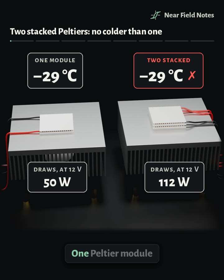 PowerPeltier stacks
Does stacking two Peltier modules make it colder?
Read Note 41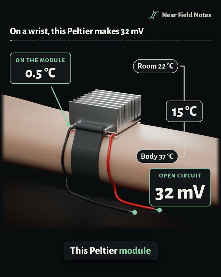 PowerPeltier generator
What does a Peltier module make when it’s run as a generator?
Read Note 40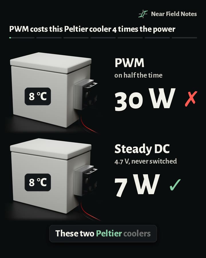 PowerPeltier coolers
Should you drive a Peltier cooler with PWM or steady DC?
Read Note 39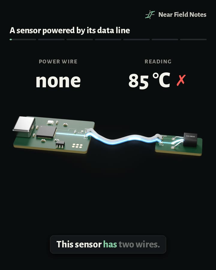 Signal integrity1-Wire
How does a sensor run on just ground and data?
Read Note 38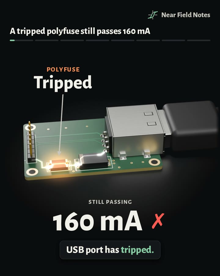 PowerFuses
What do a chip fuse, a polyfuse and an eFuse do when a USB port shorts?
Read Note 37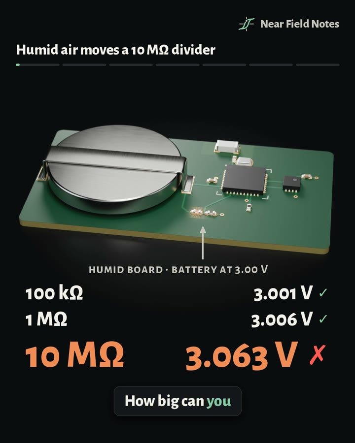 SensingHumidity leakage
How big can a resistor divider get before humid air moves it?
Read Note 34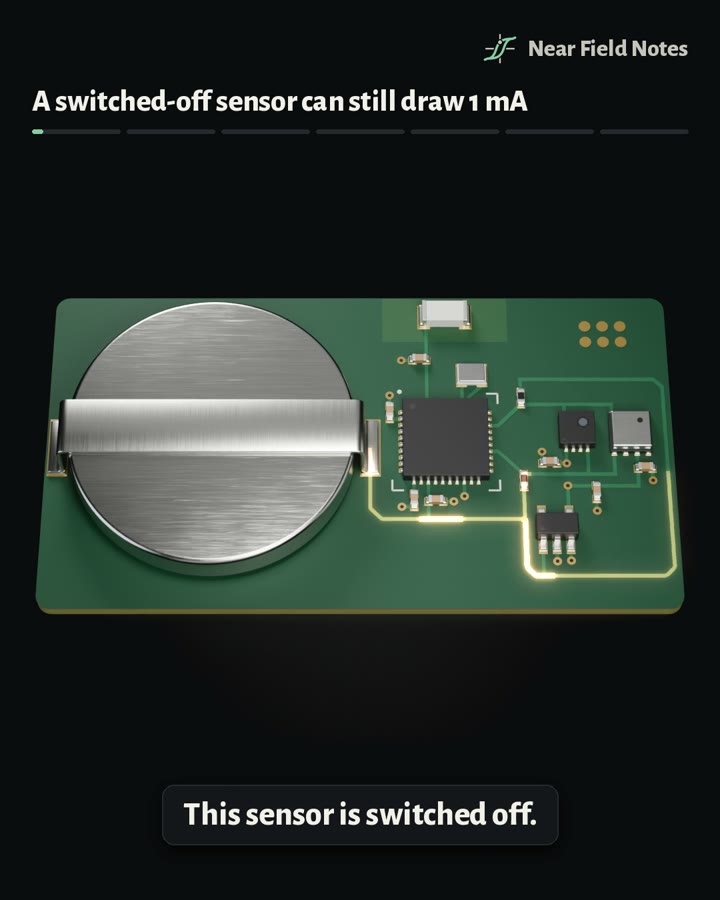 PowerBack-powering
Why does a switched-off sensor still draw 1 mA?
Read Note 33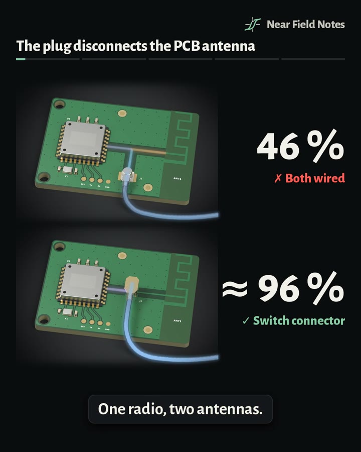 RFSwitch connector
Why not wire a radio to both of its antennas?
Read Note 32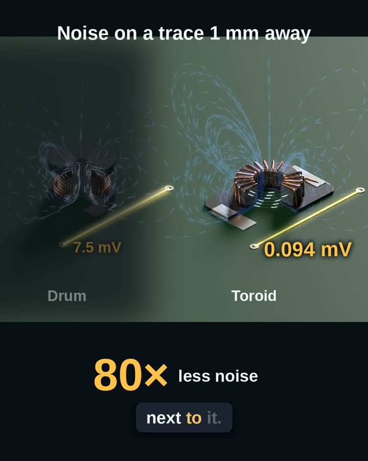 PowerPower inductors, part 2
Is a toroid the quietest inductor?
Read Note 36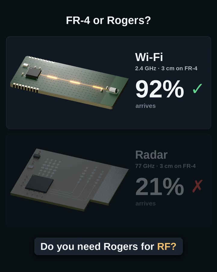 Board and fabPCB materials
Do you need Rogers for RF?
Read Note 30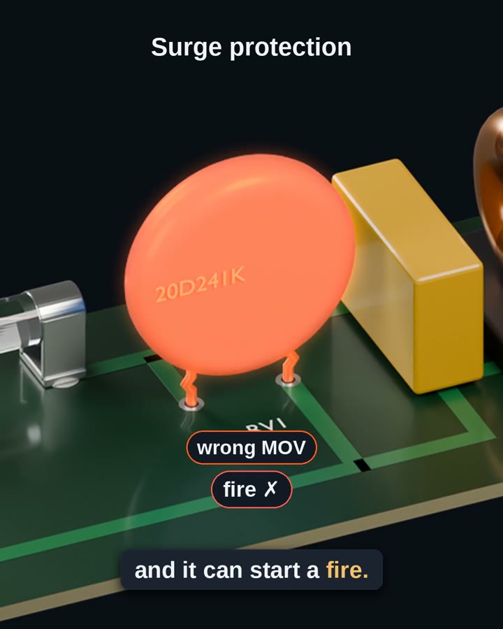 EMCMOV
How can an MOV start a fire?
Read Note 35 HistorySilicon Valley’s Superfund sites
Which county in America has the most Superfund sites?
Read Note 31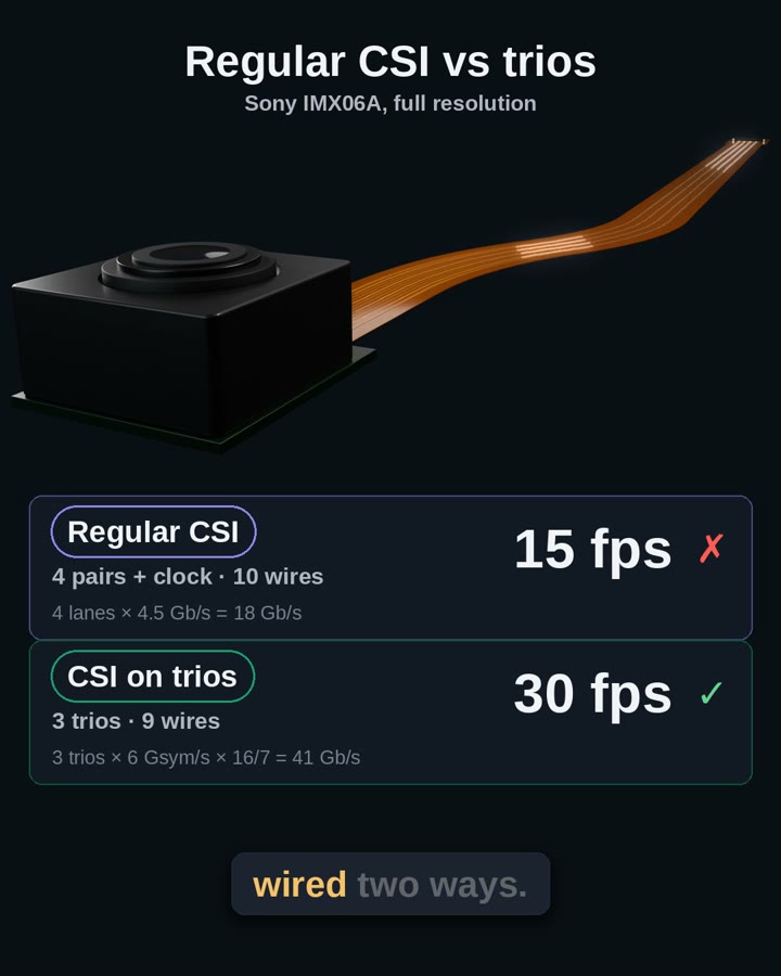 Signal integrityCSI trios
How do C-PHY trios carry a camera’s video, and how do they compare with regular CSI?
Read Note 29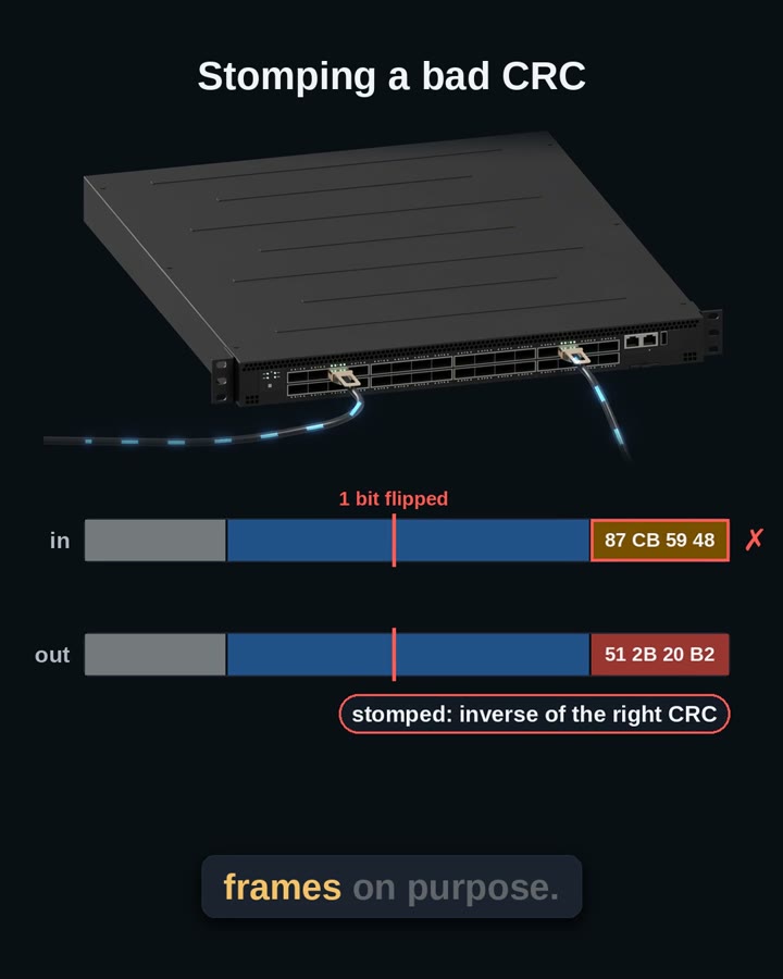 Signal integrityCRCs on fast links
How does a CRC catch bad bits, and what do fast links do when it fails?
Read Note 28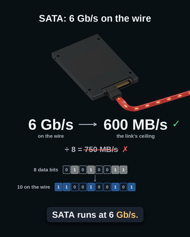 Signal integrityLine codes
Why do fast serial links use line codes like 8b/10b?
Read Note 26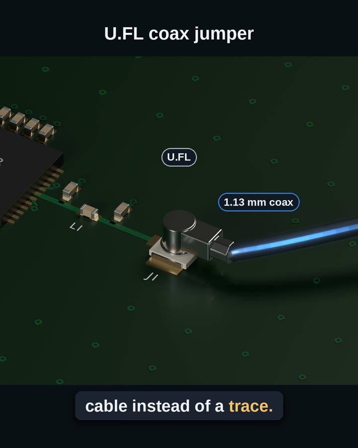 RFTrace or U.FL jumper
When does a U.FL jumper beat a trace to the antenna?
Read Note 25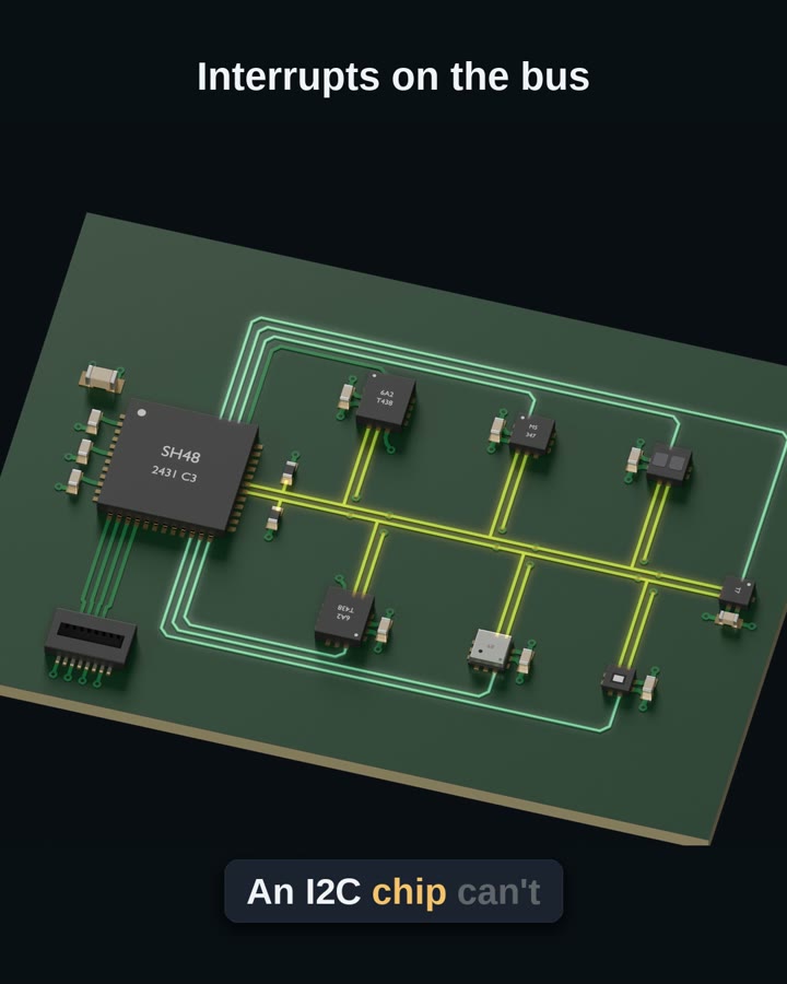 Signal integrityI3C vs I2C
What is I3C, and how does it differ from I2C?
Read Note 24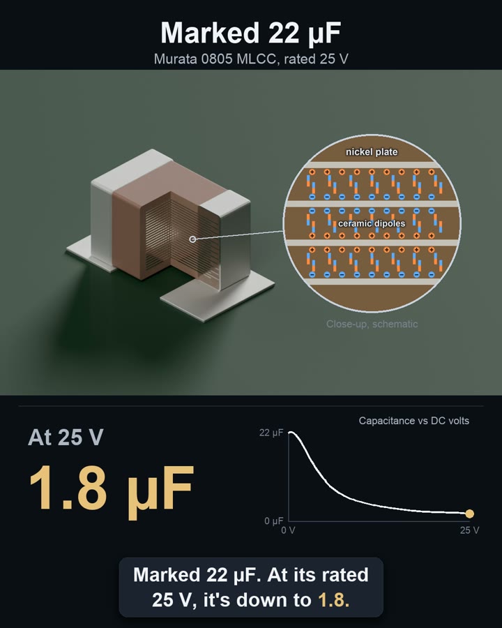 PowerCapacitors
Which kind of capacitor should feed a load?
Read Note 13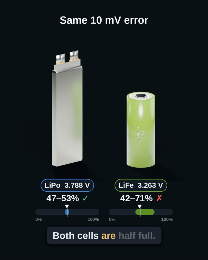 PowerLiPo vs LiFePO4
How does a LiFePO4 cell differ from a LiPo?
Read Note 18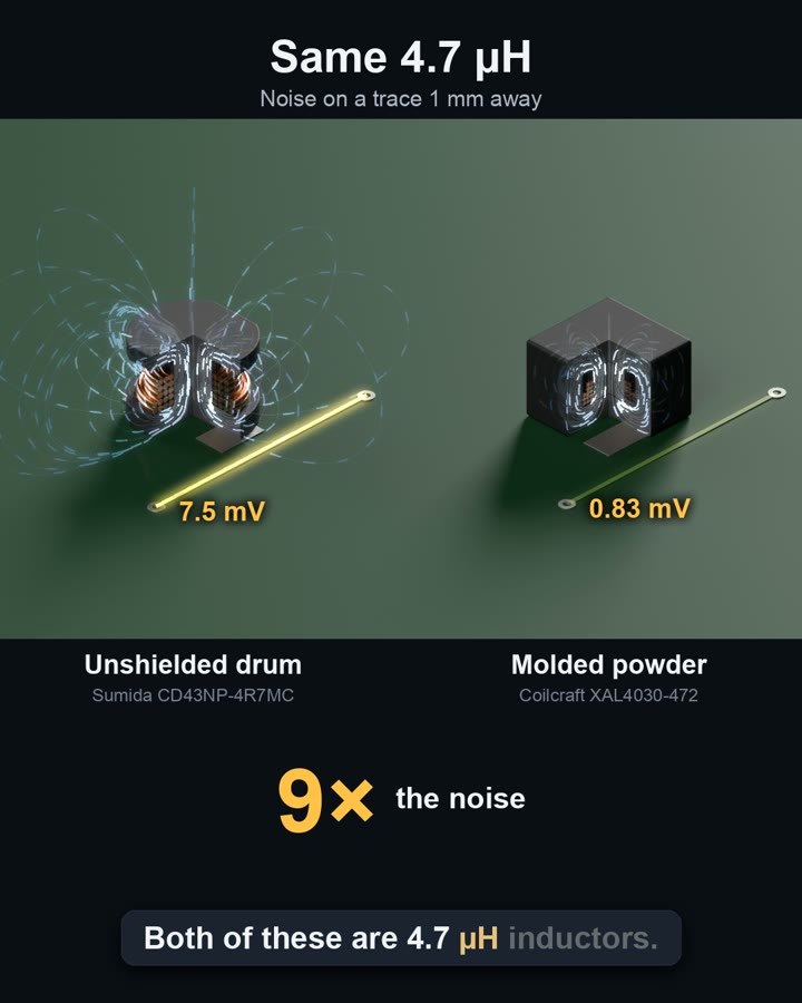 PowerPower inductors
Does it matter how a 4.7 µH inductor is built?
Read Note 12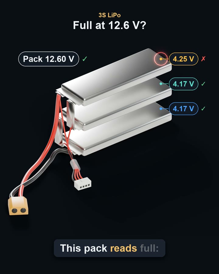 PowerBattery balance
Why does a LiPo pack need balancing?
Read Note 15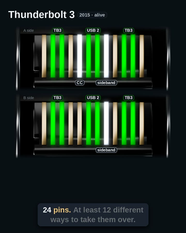 Signal integrityUSB-C alt modes
What can a USB-C port carry besides USB?
Read Note 23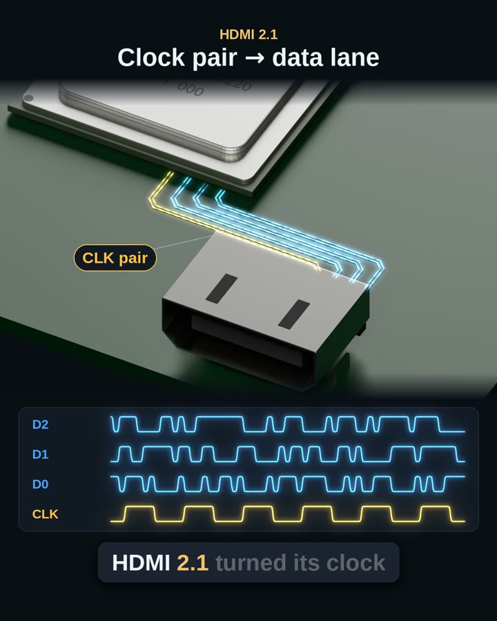 Signal integrityPHY and link layer
What does the PHY do, and what does the link layer do?
Read Note 14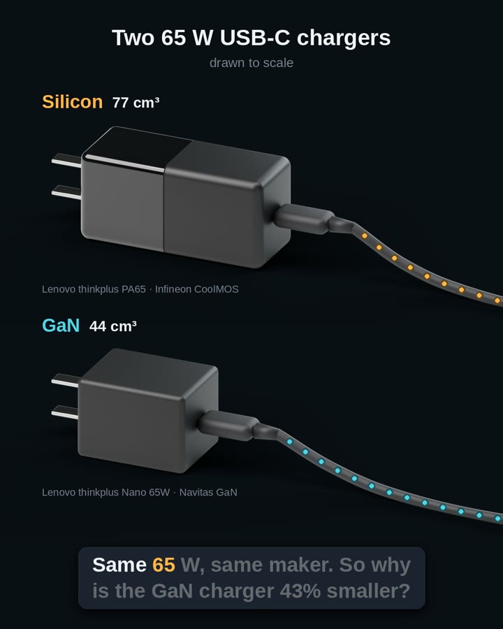 PowerGaN vs silicon
Why are USB-C chargers going GaN?
Read Note 11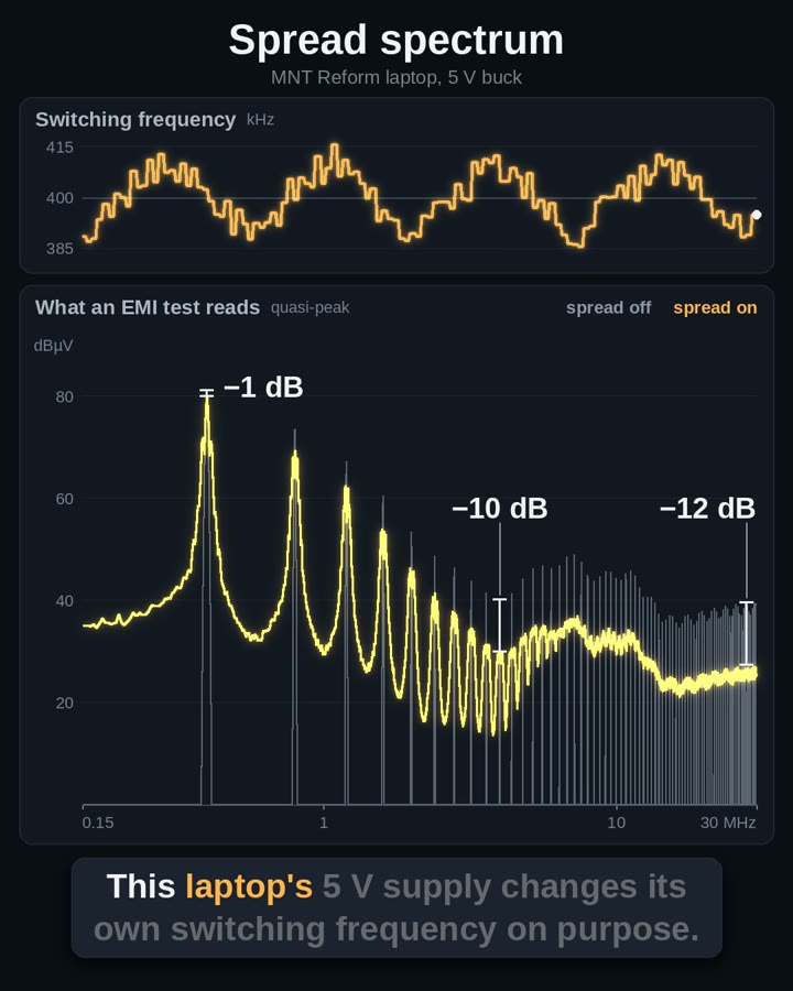 EMCSpread spectrum
What does spread spectrum do to a buck’s EMI test?
Read Note 6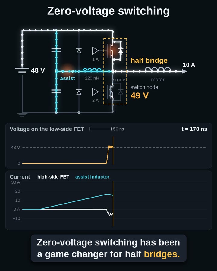 PowerZero-voltage switching
What is zero-voltage switching, and what does it save?
Read Note 10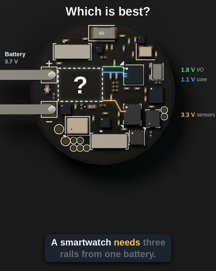 PowerSIMO converters
Can one inductor feed three rails?
Read Note 22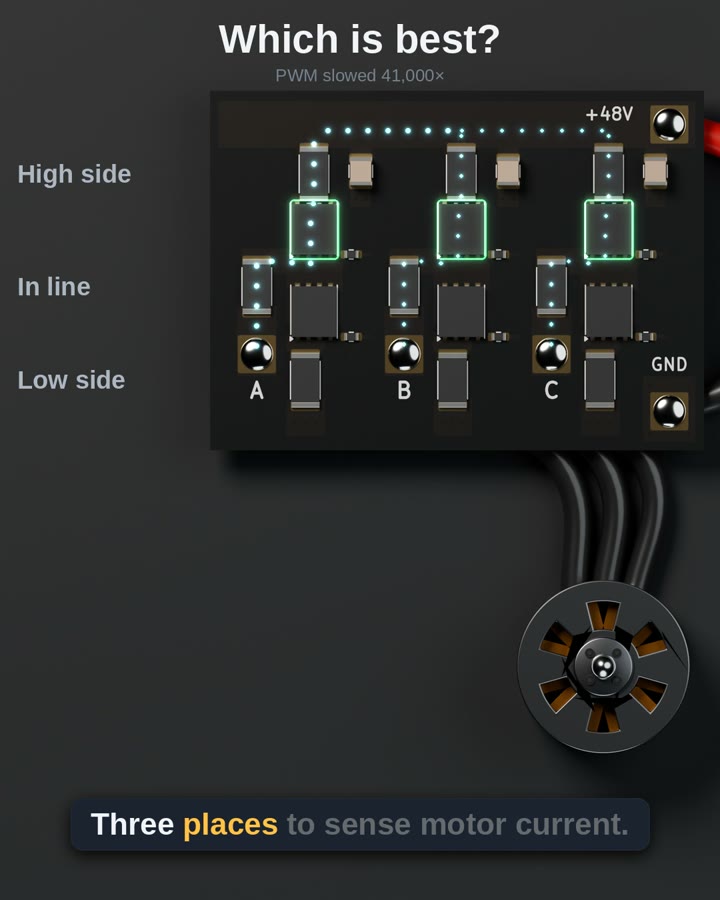 SensingSense position
Low side, high side or in line: where should a motor drive sense current?
Read Note 19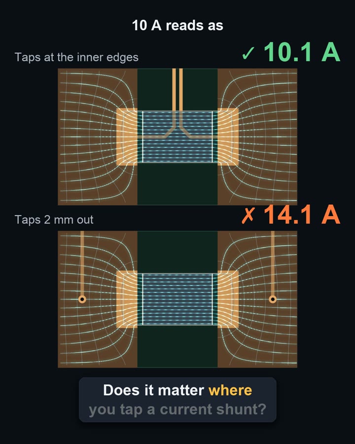 SensingShunt taps
Where do you tap a 0.5 mΩ shunt?
Read Note 5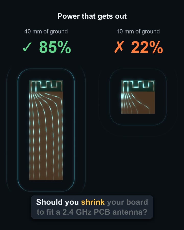 RFAntenna ground
How much ground does a 2.4 GHz PCB antenna need?
Read Note 3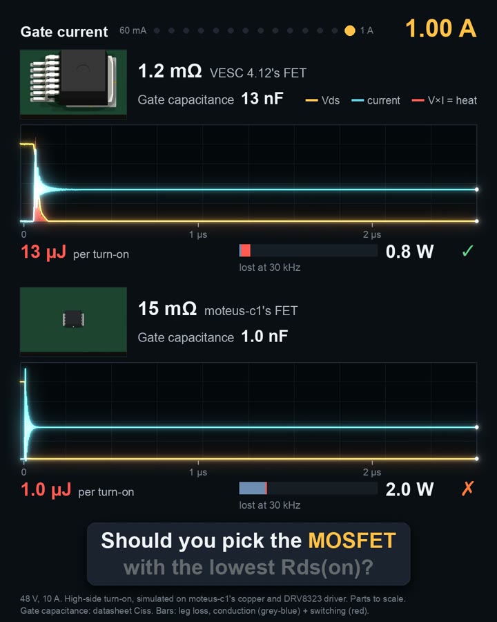 PowerFET choice
Is the FET with the lowest Rds(on) the best one?
Read Note 20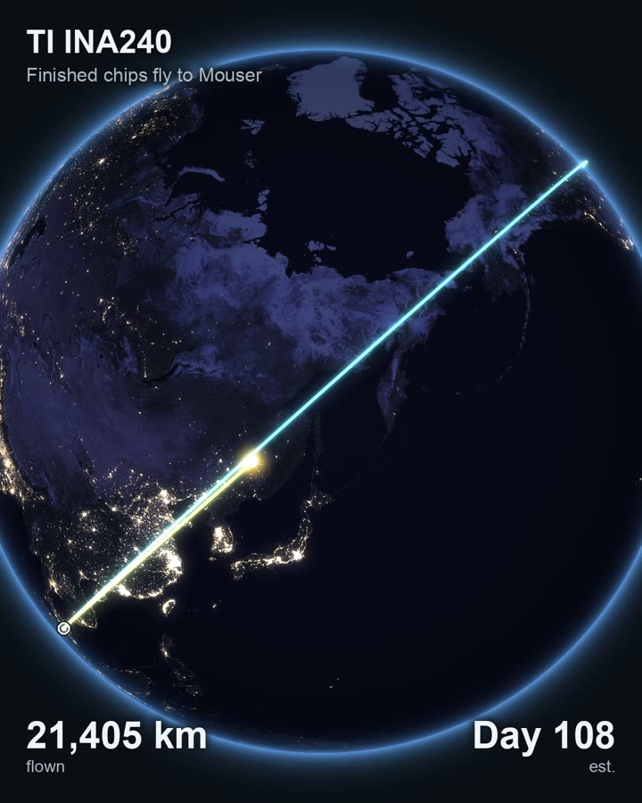 LogisticsChip journeys
Where does a chip travel before it reaches your board?
Read Note 9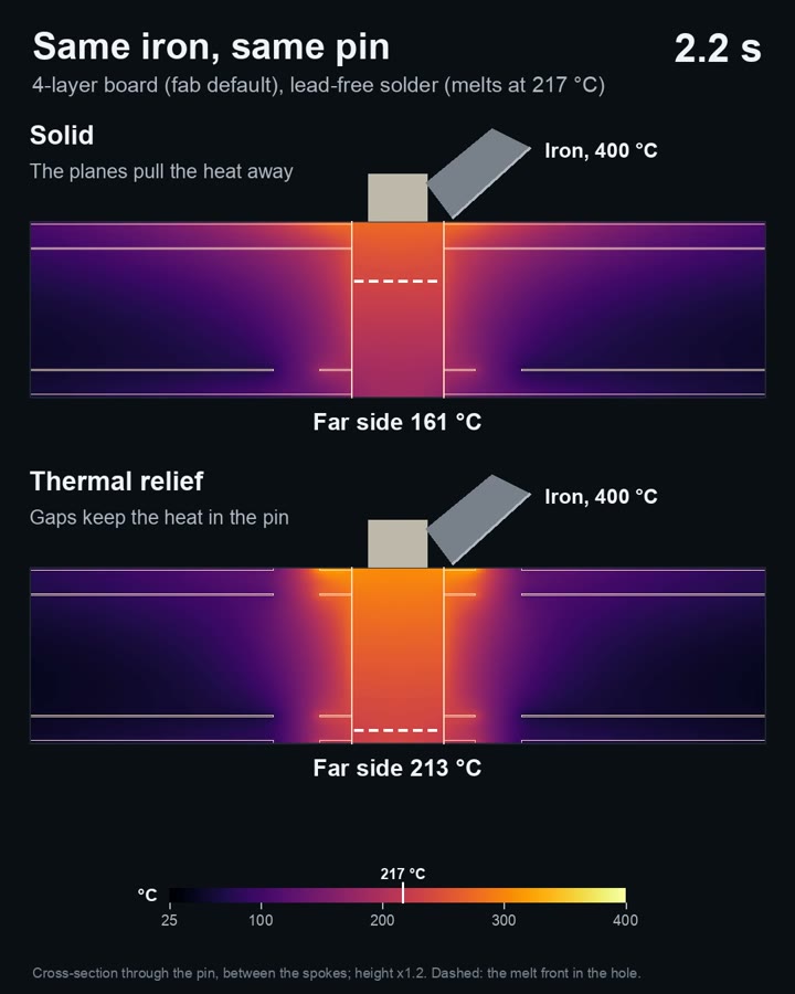 Board and fabThermal relief
Should a ground pin tie into the plane through a thermal relief?
Read Note 7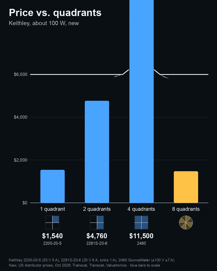 PowerPower quadrants
What are 1-, 2- and 4-quadrant power supplies?
Read Note 21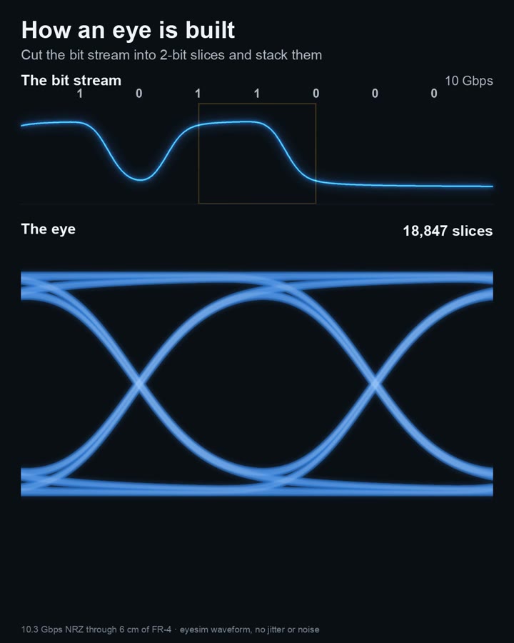 Signal integrityEye diagram
How do you read an eye diagram?
Read Note 8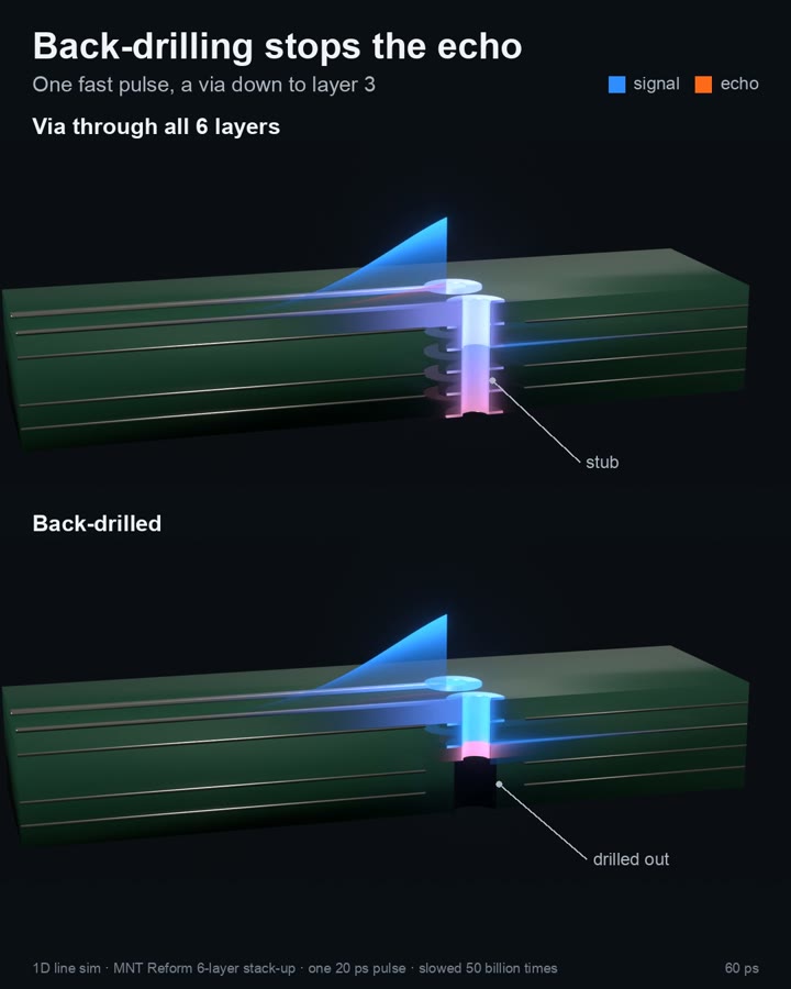 Signal integrityVia stubs
How long a via stub can a fast link take?
Read Note 17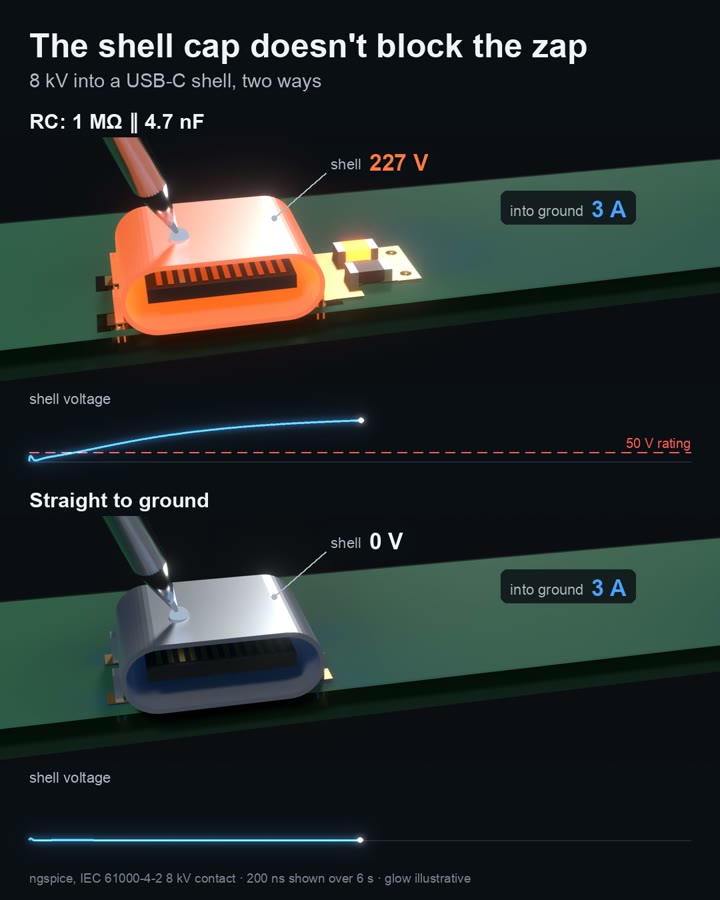 EMCUSB-C shell
Should a USB-C shell go straight to ground, or through an RC?
Read Note 2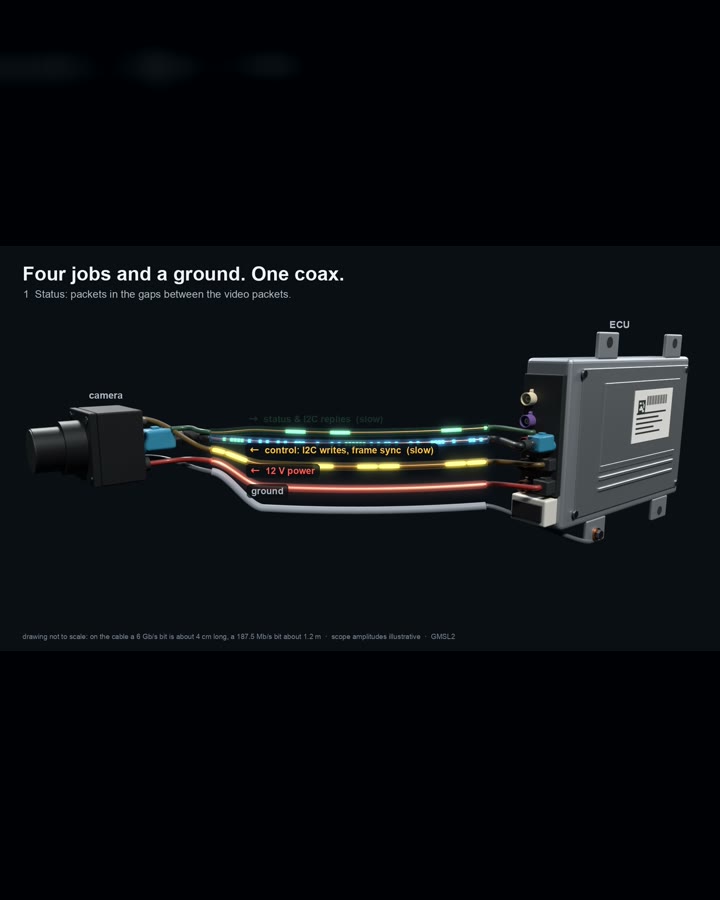 Signal integrityCar camera coax
How does one coax carry a car camera’s video, control and power?
Read Note 27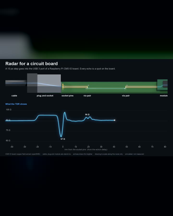 Signal integrityTDR
How do you read a TDR trace?
Read Note 16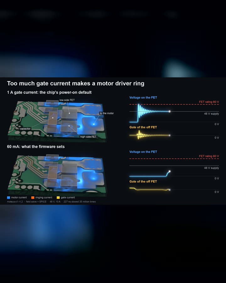 PowerGate ringing
How hard should you drive a half bridge?
Read Note 4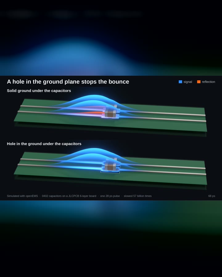 Signal integrityGround cut
Should you cut ground under connector pads?
Read Note 1