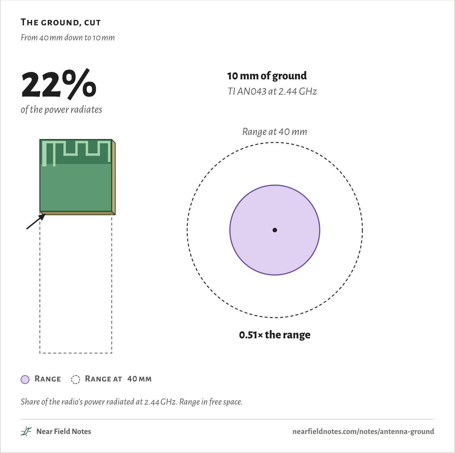
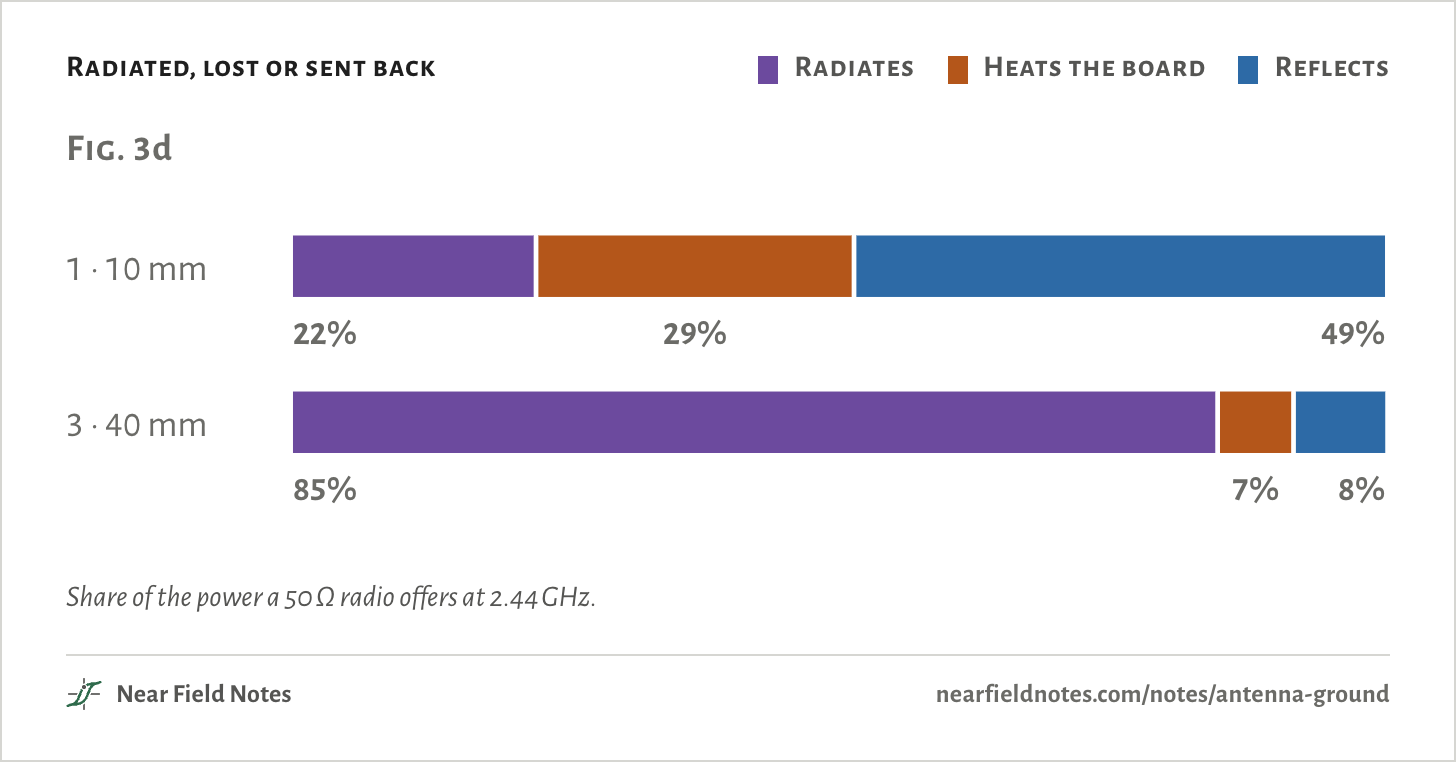
About 40 mm behind the antenna. With 10 mm, 22% of the power gets out, and a perfect matching network only lifts that to 43%.
The ground, cut
From 40 mm down to 10 mm
Range
Range at 40 mm
Share of the radio’s power radiated at 2.44 GHz. Range in free space.
The antenna and its ground
TI’s CC2511 USB dongle
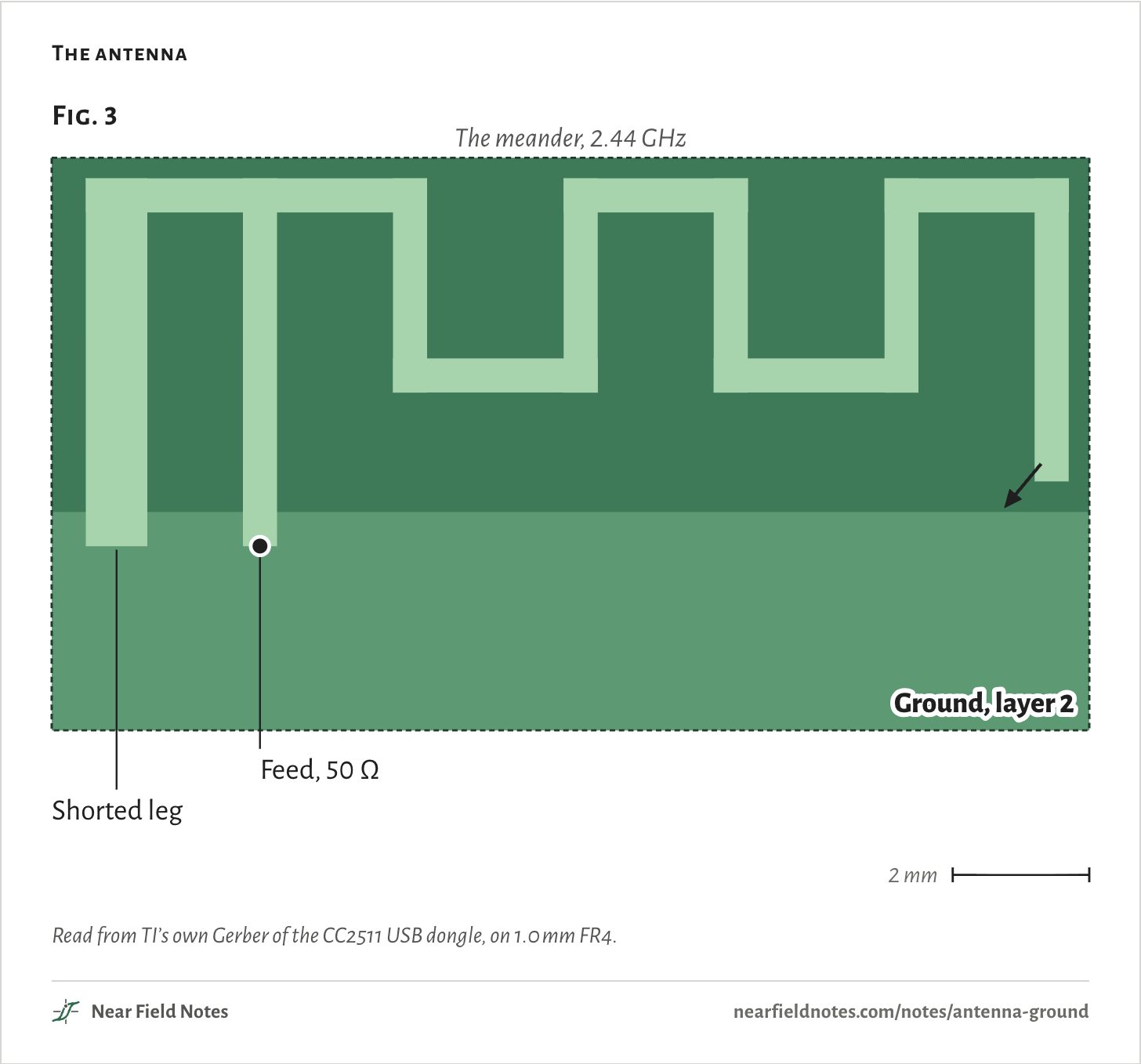
TI’s AN043 antenna is a copper meander across the end of a 15.2 mm wide board. Two legs reach down over the edge of the ground on layer 2. One is shorted to it and the other is fed from it. The ground is the other half of the antenna, and current runs along it too. Shrink the board and that half gets cut short.
The antenna
Read from TI’s own Gerber of the CC2511 USB dongle, on 1.0 mm FR4.
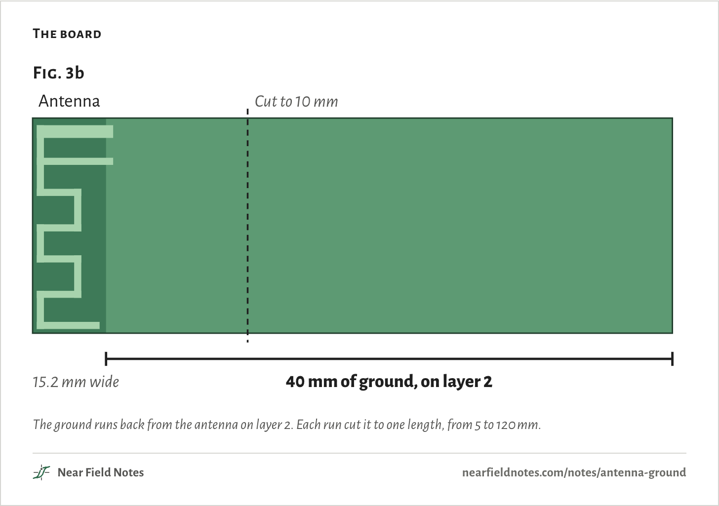
The board
The ground runs back from the antenna on layer 2. Each run cut it to one length, from 5 to 120 mm.
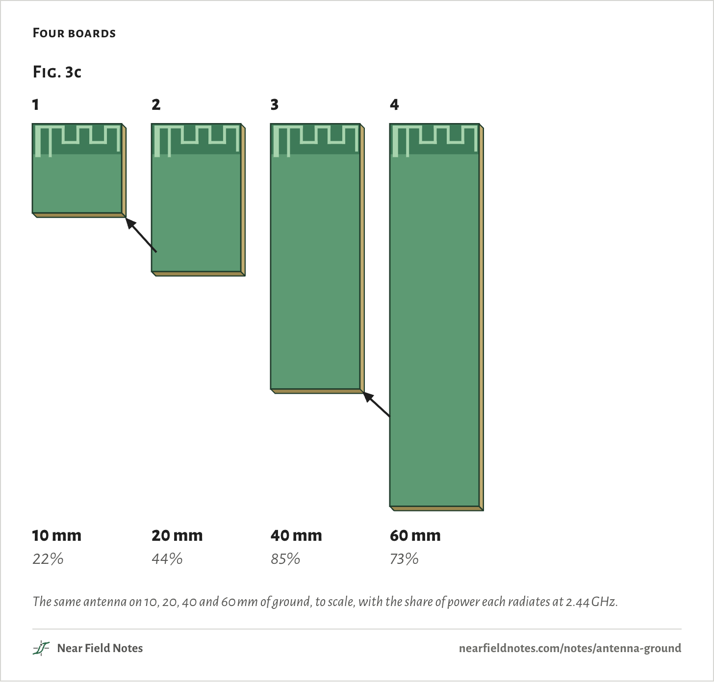
Four boards
The same antenna on 10, 20, 40 and 60 mm of ground, to scale, with the share of power each radiates at 2.44 GHz.
72
Antenna ground
Specimen 3 radiates about four times what specimen 1 does
Field marks. Specimen 3 has 40 mm of ground behind the antenna. 85% radiates.
Look-alike. Specimen 1 has the same antenna on 10 mm. 22% radiates.
Range. Specimen 1 reaches about half as far in free space: r10r40=P10P40=22%85%=0.51
Habitat.TI AN043 from the CC2511 dongle. 1.0 mm FR4, 15.2 mm wide, 2.44 GHz.
73
Where the power goes
Specimens 1 and 3
Radiated, lost or sent back
Radiates
Heats the board
Reflects
Share of the power a 50 Ω radio offers at 2.44 GHz.
74
Key to antenna ground
How much ground does a 2.4 GHz PCB antenna need?
1aRoom for 40 mm of ground behind the antenna85% radiates
1bRoom for only 10 mmGo to 2
2aA matching network tuned to it43% radiates
2bThe antenna as built22% radiates
A perfect match stops the reflection. The 10 mm board still turns 57% of what it takes in into heat.
75
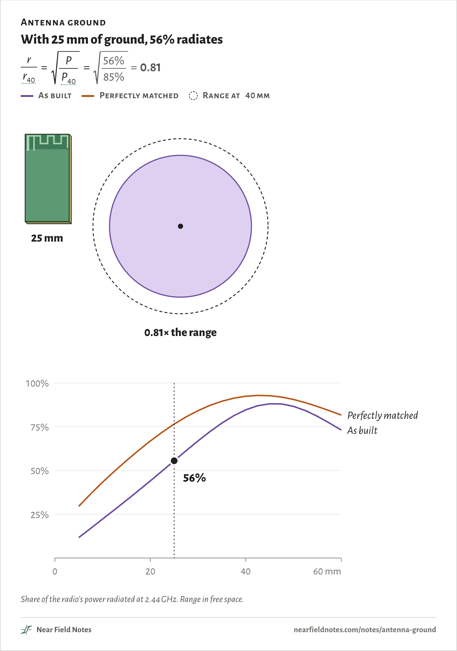
Cut the ground yourself
5 to 60 mm, every 2.5 mm
Antenna ground
With 25 mm of ground, 56% radiates
rr40=PP40=56%85%=0.81
As built
Perfectly matched
Range at 40 mm
Share of the radio’s power radiated at 2.44 GHz. Range in free space.
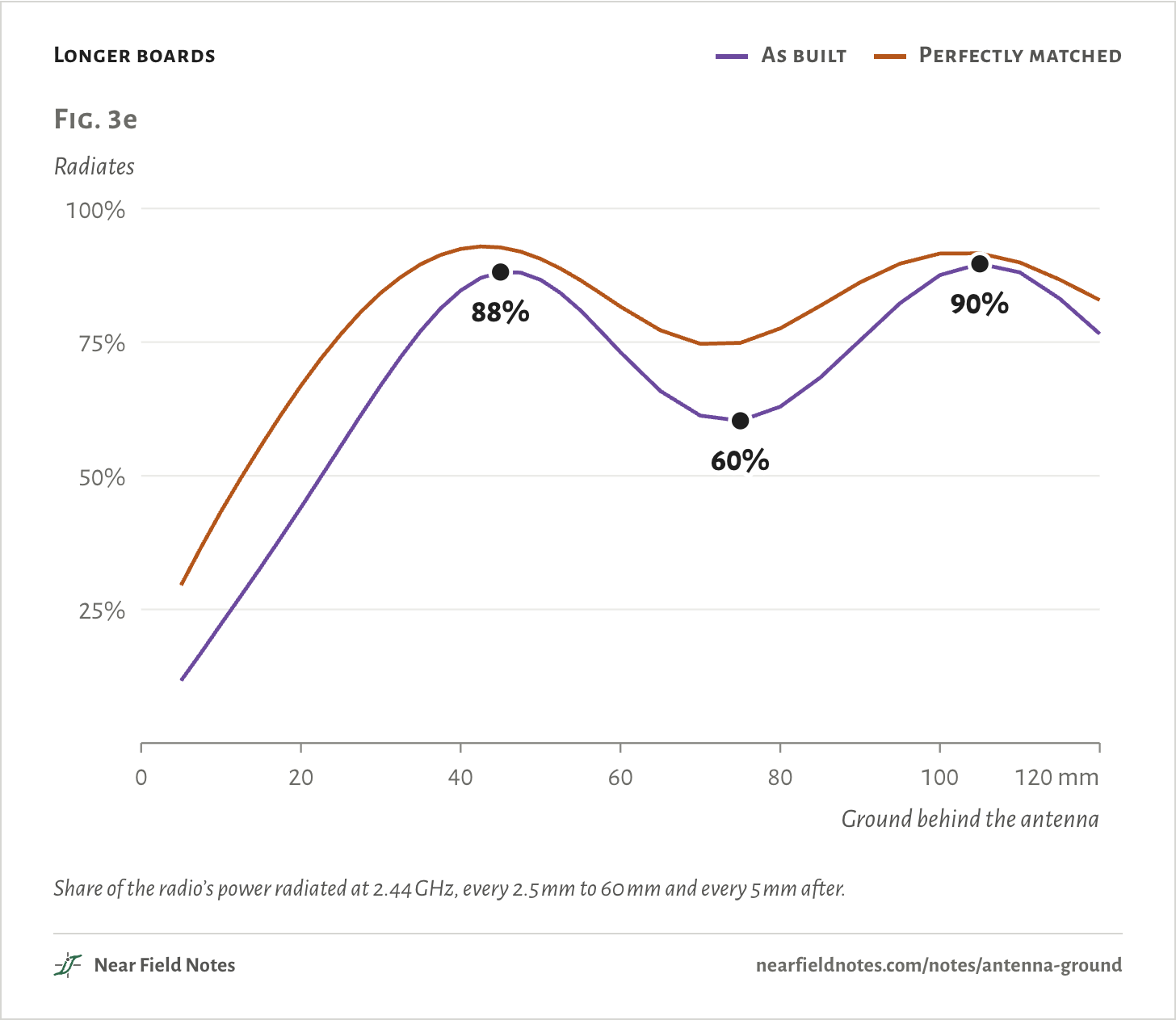
Longer boards
As built
Perfectly matched
Share of the radio’s power radiated at 2.44 GHz, every 2.5 mm to 60 mm and every 5 mm after.
76
Longer boards
More ground stops helping past 46 mm
Field marks. Past 46 mm, more ground makes it worse. At 75 mm only 60% radiates.
Look-alike. At 105 mm it climbs back to 90%.
Range. The peaks sit 59 mm apart, about half a wavelength at 2.44 GHz. The ground is part of the antenna, so its length tunes it too. In TI’s own test, plugging the dongle into a laptop cut its bandwidth from about 250 to 100 MHz.
77
Conditions
Antenna
TI AN043 meandered inverted-F, from TI’s Gerber of the CC2511 USB dongle reference design, rev 1.3
Board
4-layer FR4, 1.0 mm, εr 4.5, 15.2 mm wide
Ground
Layer 2, 0.25 mm below the antenna, cut to each length from 5 to 120 mm
Source
50 Ω at 2.44 GHz
Measure
Radiated power over the power the source can deliver
Solver
openEMS, rechecked on a 0.125 mm mesh
Check
TI’s dongle resonates at 2.525 GHz in the model and 2.49 GHz in TI’s measurement, 1.4% apart
Simulated only. TI’s 2.49 GHz is the one measured number on this page.
Limits
Range here is free-space range. Walls, hands and cases change it.
The model has no case, hand or laptop. TI’s own measurement shows a laptop can move the result.
Files
antsim/geom.pyThe antenna’s copper, read from TI’s Gerber
antsim/run.pyOne board, reduced to its power balance
post/matched.pyThe best matching network for each board