Near Field Notes

Note 15PowerRev 1Watch the video · 2:26

Battery balance

Why does a LiPo pack need balancing?

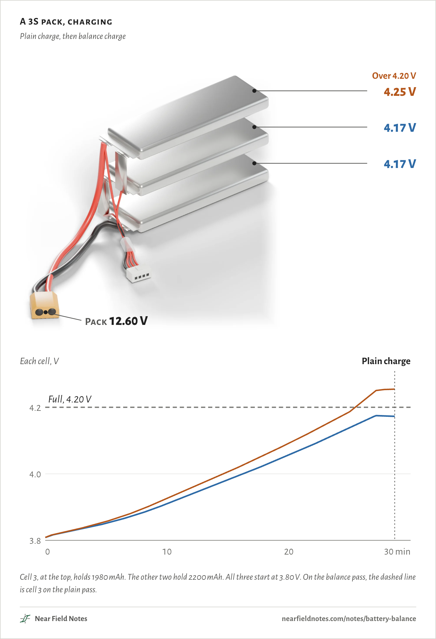
Because a plain charger watches only the total. On a 3S pack with one cell faded to 90%, a plain charge stops at 12.60 V with that cell at 4.25 V, past its 4.20 V limit. A balance charge watches every cell and stops each one at 4.20 V.

The figure charges the same pack twice at 2.2 A. First plain, through its main plug alone. Then with its balance lead plugged in, so the charger can bleed 300 mA off the cell that leads.

A 3S pack, charging

Plain charge, then balance charge

4.17 V4.17 V4.25 VOver 4.20 VBleedingPack 12.60 VEach cell, VPlain chargeBalance charge3.84.04.20102030 minFull, 4.20 V4.17 V4.17 V4.25 VOver 4.20 VBleedingPack 12.60 VEach cell, VPlain chargeBalance charge3.84.04.20102030 minFull, 4.20 V4.17 V4.17 V4.25 VOver 4.20 VBleedingPack 12.60 VEach cell, VPlain chargeBalance charge3.84.04.20102030 minFull, 4.20 V

Cell 3, at the top, holds 1980 mAh. The other two hold 2200 mAh. All three start at 3.80 V. On the balance pass, the dashed line is cell 3 on the plain pass.

The numbers
ChargeTookCells 1 and 2Cell 3, weakPackLost as heat
Plain29 min4.17 V4.25 V12.60 Vnone
Balance, 300 mA bleed29 min4.20 V4.20 V12.60 V0.41 Wh

A 3S pack and its balance lead

Two plugs, two jobs

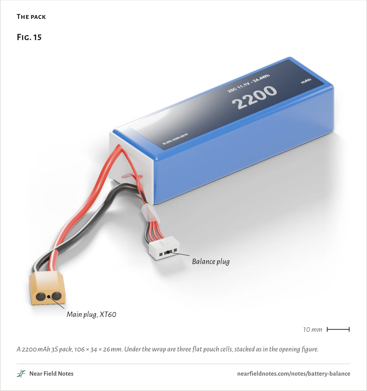
A 3S pack is three cells in series. Two thick leads carry the charge and the load through the main plug, an XT60 here. Across them, a charger sees only the total.

Four thin wires run to the balance plug, a 4-pin JST-XH. They reach both ends of the pack and both joints between cells, so a charger can read every cell.

The pack
Fig. 15Main plug, XT60Balance plug10 mmFig. 15Main plug, XT60Balance plug10 mmFig. 15Main plug, XT60Balance plug10 mm

A 2200 mAh 3S pack, 106 × 34 × 26 mm. Under the wrap are three flat pouch cells, stacked as in the opening figure.

The numbers
PlugWiresCarries
Main, XT602 thickThe charge and the load current, across the whole pack
Balance, 4-pin JST-XH4 thinEach junction between cells, for reading and balancing each cell

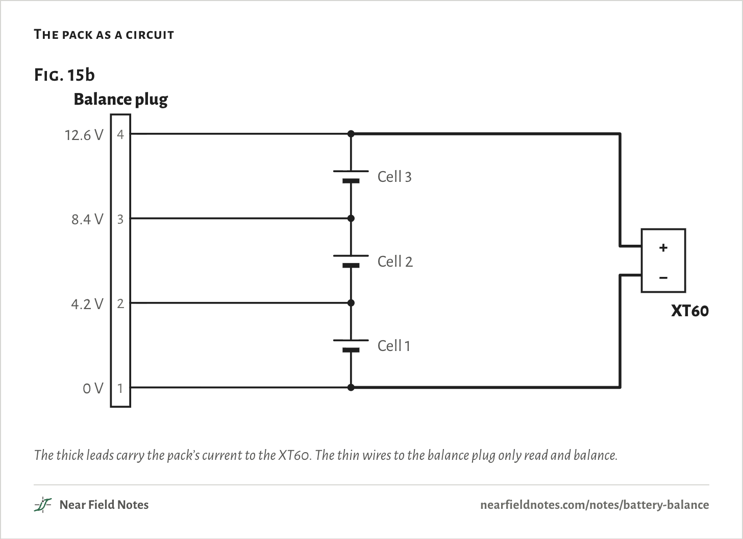
Each balance pin sits one cell above the last. With every cell full, they read 0, 4.2, 8.4 and 12.6 V.

A charger works out each cell from the difference between two neighboring pins.

The pack as a circuit
Fig. 15b0 V14.2 V28.4 V312.6 V4Balance plugCell 1Cell 2Cell 3+−XT60Fig. 15b0 V14.2 V28.4 V312.6 V4Balance plugCell 1Cell 2Cell 3+−XT60Fig. 15b0 V14.2 V28.4 V312.6 V4Balance plugCell 1Cell 2Cell 3+−XT60

The thick leads carry the pack’s current to the XT60. The thin wires to the balance plug only read and balance.

The numbers
Balance pinJoinsAt full
1The pack’s −0.0 V
2Cell 1 + and cell 2 −4.2 V
3Cell 2 + and cell 3 −8.4 V
4The pack’s +12.6 V

S and P

Cells in series, cells side by side

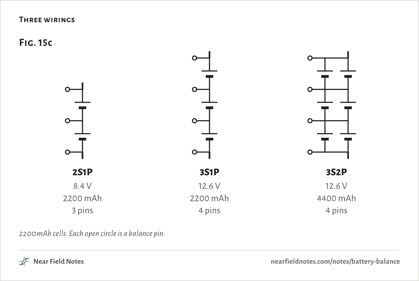
S counts cells in series. Each adds its voltage, and the same current flows through all of them.

P counts cells side by side in each group. They share the current and add their capacity. Joined, they always sit at the same voltage, so they balance as one.

The balance plug has a pin for each end and each joint, so a 3S pack takes 4 pins, whatever its P. Hobby makers’ guides draw 3S2P as two 3S strings side by side. Large packs join each group first, as drawn here.

Three wirings
Fig. 15c2S1P8.4 V2200 mAh3 pins3S1P12.6 V2200 mAh4 pins3S2P12.6 V4400 mAh4 pinsFig. 15c2S1P8.4 V2200 mAh3 pins3S1P12.6 V2200 mAh4 pins3S2P12.6 V4400 mAh4 pinsFig. 15c2S1P8.4 V2200 mAh3 pins3S1P12.6 V2200 mAh4 pins3S2P12.6 V4400 mAh4 pins

2200 mAh cells. Each open circle is a balance pin.

The numbers
WiringCellsFullCapacityBalance pins
2S1P28.4 V2200 mAh3
3S1P312.6 V2200 mAh4
3S2P612.6 V4400 mAh4

A plain charge

What the charger sees

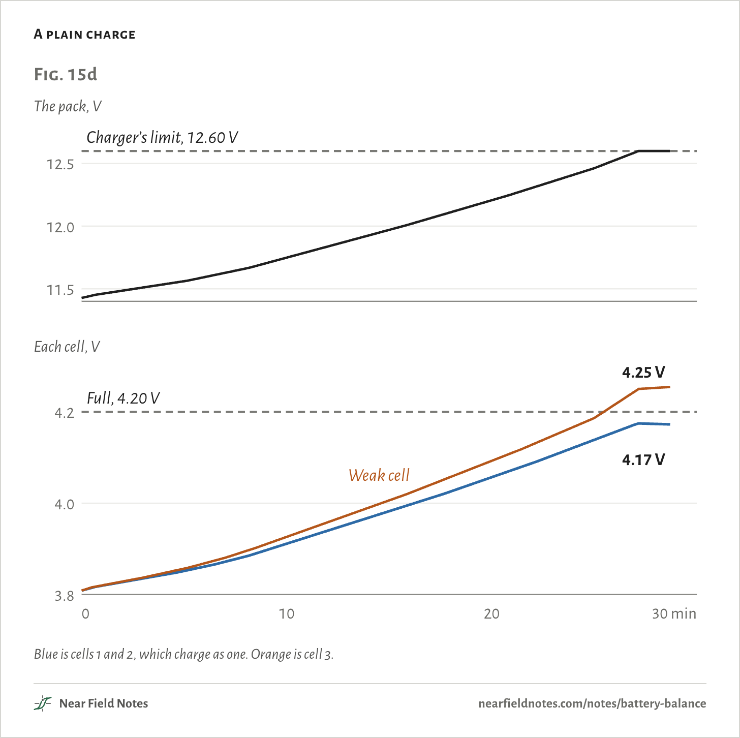
A plain charge leaves the balance lead out and works on the total. It pushes 2.2 A until the pack reads 12.60 V, then holds 12.60 V while the current tapers off. It stops at 220 mA, after 29 min.

Vpack=V1+V2+V3

4.173 V+4.173 V+4.254 V=12.600 V

The total comes out right. The cells don’t. Cell 3 holds 10% less, so the same current fills it faster. It passes 4.20 V after 26 min and ends at 4.25 V, 82 mV above the others.

One LiPo maker gives 4.25 V as the absolute maximum, never to be passed. A cell only 5% short still ends at 4.23 V.

Cells from one batch still differ in capacity, resistance and self-discharge, and TI notes that the gaps grow with use. The weak cell is the one that ends high, and each overcharge weakens it further.

A plain charge
Fig. 15dThe pack, V11.512.012.5Each cell, V3.84.00102030 min4.2Charger’s limit, 12.60 VFull, 4.20 V4.25 V4.17 VFig. 15dThe pack, V11.512.012.5Each cell, V3.84.00102030 min4.2Charger’s limit, 12.60 VFull, 4.20 V4.25 V4.17 VWeak cellFig. 15dThe pack, V11.512.012.5Each cell, V3.84.00102030 min4.2Charger’s limit, 12.60 VFull, 4.20 V4.25 V4.17 VWeak cell

Blue is cells 1 and 2, which charge as one. Orange is cell 3.

The numbers
MinutePack, VCells 1 and 2, VCell 3, V
011.4263.8093.809
511.5603.8523.857
1011.7483.9103.927
1511.9693.9824.006
2012.2064.0574.092
2512.4624.1384.187
28.7, end12.6004.1734.254

What 4.25 V costs

Cycle life against charge voltage

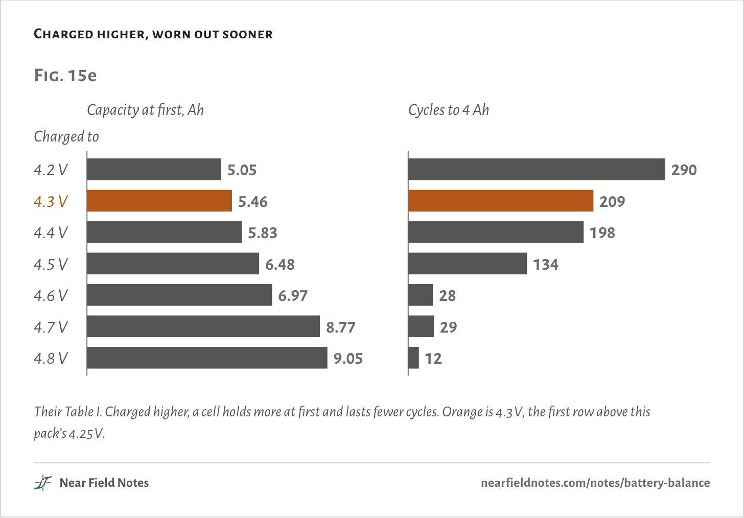
Nobody has published cycle life at 4.25 V. The nearest data is a 2020 study by Juarez-Robles and others. They cycled 5 Ah LiCoO2 pouch cells at 1C to seven charge voltages, until each held only 4 Ah.

Charged higher, worn out sooner
Fig. 15eCharged toCapacity at first, Ah5.055.465.836.486.978.779.05Cycles to 4 Ah2902091981342829124.2 V4.3 V4.4 V4.5 V4.6 V4.7 V4.8 VFig. 15eCharged toCapacity at first, Ah5.055.465.836.486.978.779.05Cycles to 4 Ah2902091981342829124.2 V4.3 V4.4 V4.5 V4.6 V4.7 V4.8 VFig. 15eCharged toCapacity at first, Ah5.055.465.836.486.978.779.05Cycles to 4 Ah2902091981342829124.2 V4.3 V4.4 V4.5 V4.6 V4.7 V4.8 V

Their Table I. Charged higher, a cell holds more at first and lasts fewer cycles. Orange is 4.3 V, the first row above this pack’s 4.25 V.

The numbers
Charged toCapacity at firstCycles to 4 Ah
4.2 V5.05 Ah290
4.3 V5.46 Ah209
4.4 V5.83 Ah198
4.5 V6.48 Ah134
4.6 V6.97 Ah28
4.7 V8.77 Ah29
4.8 V9.05 Ah12
302

In flight, it empties first

10 A from the plain-charged pack

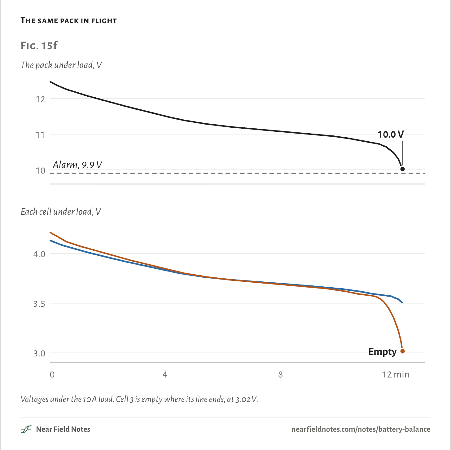
The weak cell runs out first, too. The same 10 A comes out of every cell, and it has the least to give.

A flight controller running Betaflight reads only the pack. Its docs’ example settings warn at 3.4 V a cell and alarm at 3.3 V. On a 3S pack, that’s 10.2 and 9.9 V.

Here cell 3 is empty after 12 min, while the pack still reads 10.0 V. The warning came 5 s before. The alarm never sounded.

The same pack in flight
Fig. 15fThe pack under load, V101112Each cell under load, V3.03.54.004812 minAlarm, 9.9 V10.0 VEmptyFig. 15fThe pack under load, V101112Each cell under load, V3.03.54.004812 minAlarm, 9.9 V10.0 VEmptyFig. 15fThe pack under load, V101112Each cell under load, V3.03.54.004812 minAlarm, 9.9 V10.0 VEmpty

Voltages under the 10 A load. Cell 3 is empty where its line ends, at 3.02 V.

The numbers
MinutePack, VCells 1 and 2, VCell 3, V
012.4784.1324.214
211.9173.9623.994
411.5043.8303.845
611.2283.7433.743
811.0813.6953.691
1010.9253.6473.630
12.2, empty10.0183.5013.016

Balance charging

Passive: burn the extra

A balance charge plugs in both leads. It charges through the main plug and reads every cell through the balance plug.

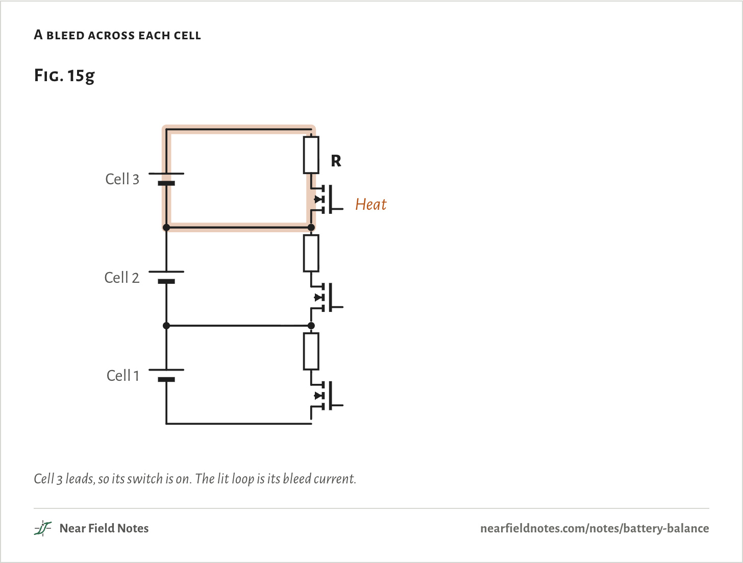
When one cell leads, the charger switches a resistor across it. Part of the charging current flows around that cell as heat, and the others catch up.

Ibleed=VcellR

=4.20 V14 Ω=300 mAand 1.26 W of heat

A bleed across each cell
Fig. 15gCell 1Cell 2Cell 3RFig. 15gCell 1Cell 2Cell 3RHeatFig. 15gCell 1Cell 2Cell 3RHeat

Cell 3 leads, so its switch is on. The lit loop is its bleed current.

The numbers
PartValue
Bleed resistor, each cell14 Ω
Bleed current at 4.20 V300 mA
Heat while on1.26 W
SwitchA MOSFET, on while its cell leads
304

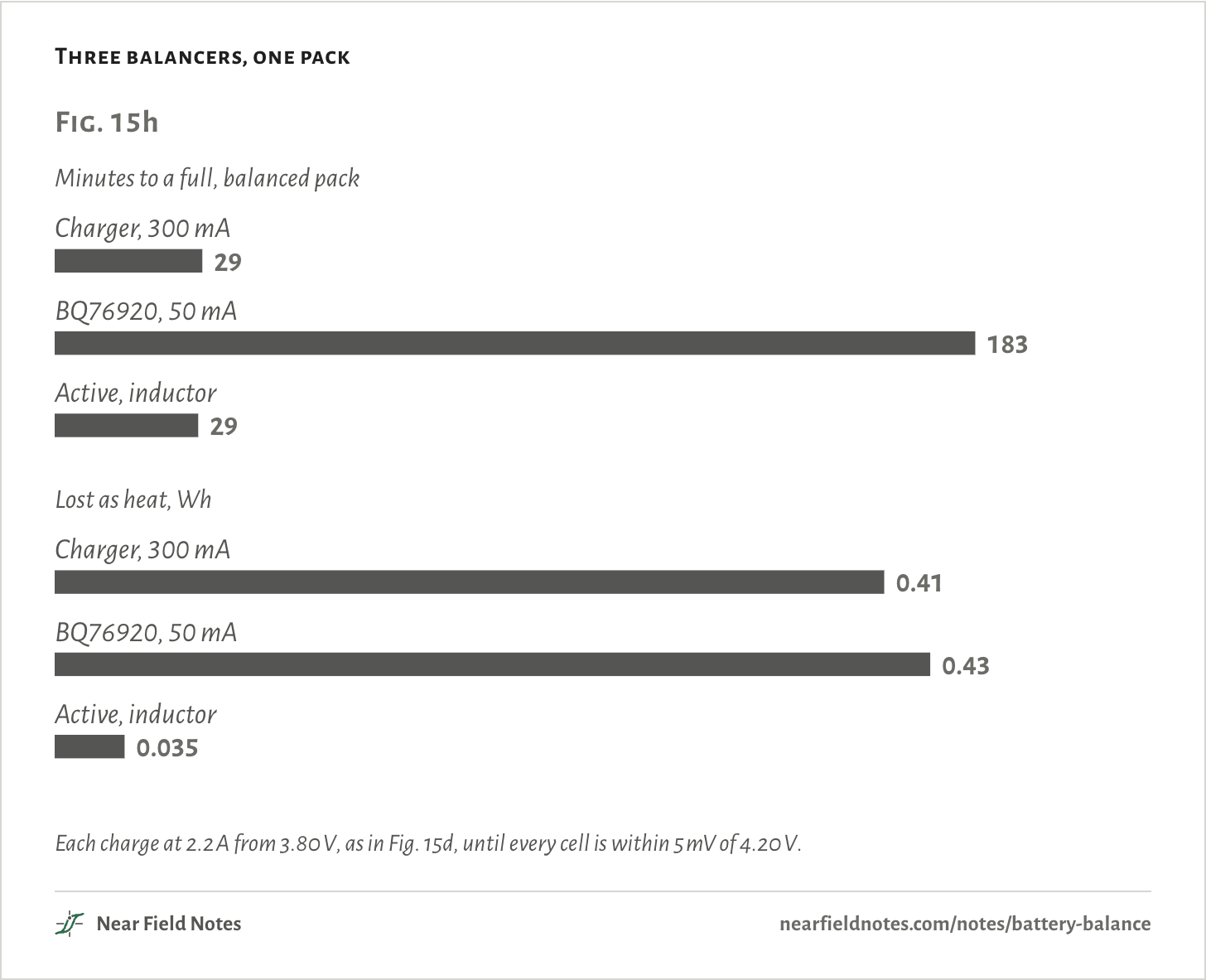
All three balancers end with every cell at 4.20 V. They differ in time and heat.

A bleed fixes the overcharge. It leaves the run time alone: cell 3 still holds 10% less, and the pack still stops when cell 3 does.

Three balancers, one pack
Fig. 15hMinutes to a full, balanced packCharger, 300 mA29BQ76920, 50 mA183Active, inductor29Lost as heat, WhCharger, 300 mA0.41BQ76920, 50 mA0.43Active, inductor0.035Fig. 15hMinutes to a full, balanced packCharger, 300 mA29BQ76920, 50 mA183Active, inductor29Lost as heat, WhCharger, 300 mA0.41BQ76920, 50 mA0.43Active, inductor0.035Fig. 15hMinutes to a full, balanced packCharger, 300 mA29BQ76920, 50 mA183Active, inductor29Lost as heat, WhCharger, 300 mA0.41BQ76920, 50 mA0.43Active, inductor0.035

Each charge at 2.2 A from 3.80 V, as in Fig. 15d, until every cell is within 5 mV of 4.20 V.

The numbers
BalancerCurrentFull and balanced inLost as heat
Charger’s bleed300 mA29 min0.412 Wh
BQ76920 bleed50 mA, 70% of the time183 min0.435 Wh
Inductor, active825 mA out of the high cell29 min0.035 Wh

Balance near the top

Where a gap shows

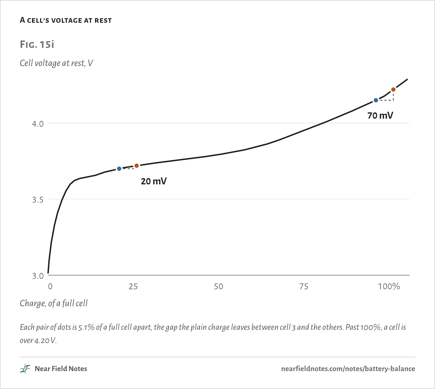
A balancer goes by voltage, and a cell’s voltage barely moves through the middle of its charge. A gap between cells hides there. A LiFe hides it almost to the end, as Note 18 shows.

The same 5% gap in charge reads as 20 mV at 3.70 V and 70 mV at 4.15 V. Near full, the gap is easy to see.

A cell’s voltage at rest
Fig. 15iCell voltage at rest, V3.03.54.00255075100%Charge, of a full cell20 mV70 mVFig. 15iCell voltage at rest, V3.03.54.00255075100%Charge, of a full cell20 mV70 mVFig. 15iCell voltage at rest, V3.03.54.00255075100%Charge, of a full cell20 mV70 mV

Each pair of dots is 5.1% of a full cell apart, the gap the plain charge leaves between cell 3 and the others. Past 100%, a cell is over 4.20 V.

The numbers
Cell atCharge5.1% more chargeVoltage gap
3.70 V20.9%3.720 V20 mV
3.80 V52.0%3.822 V22 mV
3.90 V69.0%3.945 V45 mV
4.00 V80.6%4.048 V48 mV
4.10 V91.2%4.152 V52 mV
4.15 V96.1%4.220 V70 mV

Active balancing

Move the charge instead

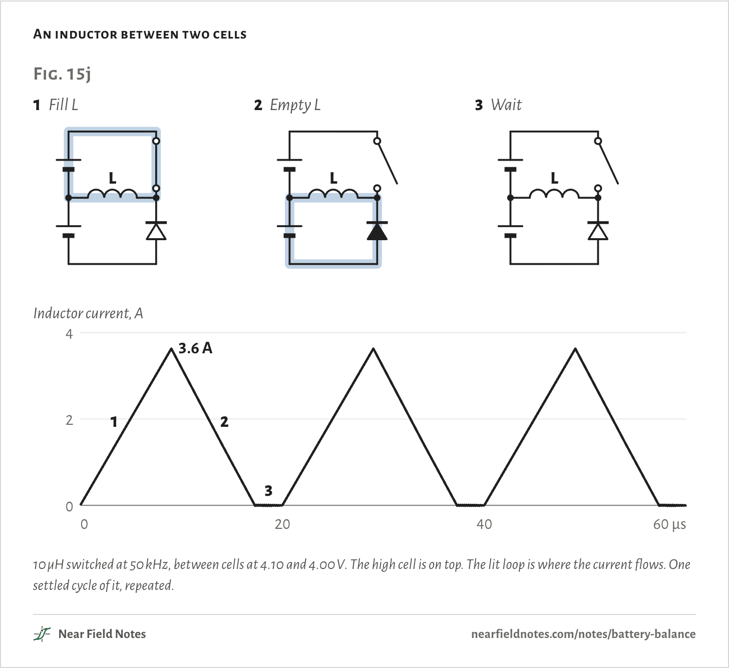
An active balancer moves charge out of a full cell and into an empty one. With an inductor, it takes three steps, 50,000 times a second.

An inductor between two cells
Fig. 15j1Fill LL2Empty LL3WaitLInductor current, A0240204060 µs1233.6 AFig. 15j1Fill LL2Empty LL3WaitLInductor current, A0240204060 µs1233.6 AFig. 15j1Fill LL2Empty LL3WaitLInductor current, A0240204060 µs1233.6 A

10 µH switched at 50 kHz, between cells at 4.10 and 4.00 V. The high cell is on top. The lit loop is where the current flows. One settled cycle of it, repeated.

The numbers
StepFromToConductingInductor current
1, fill L0 µs9 µsThe switch, from the high cell0 to 3.63 A
2, empty L9 µs17.3 µsThe diode, into the low cell3.63 A to 0
3, wait17.3 µs20 µsNothing0

Less arrives than leaves. The rest heats the switch, the diode and the inductor’s copper:

η=VlowIinVhighIout

=4.00 V × 0.741 A4.10 V × 0.825 A=88%

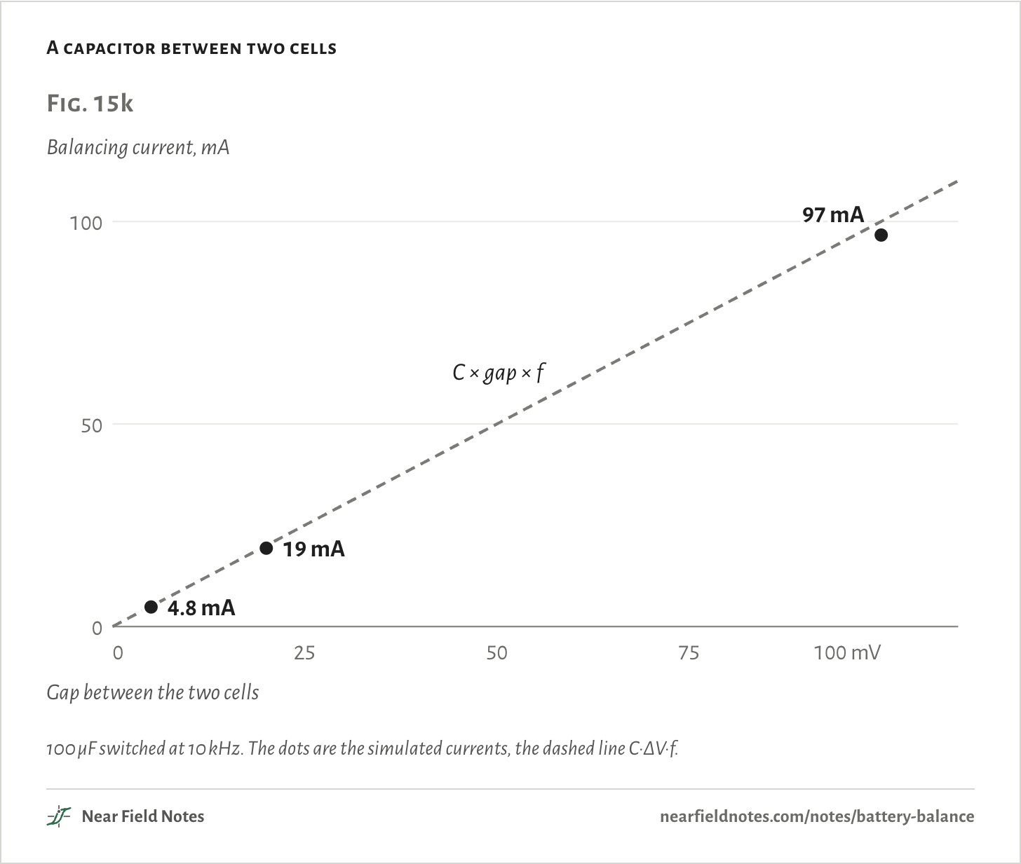
A capacitor can carry charge too. It connects across the higher cell, then across the lower one, and takes a little charge down each time:

I=C·ΔV·f

=100 µF × 100 mV × 10 kHz=100 mAagainst 97 mA simulated

The current follows the gap: 19 mA at 20 mV, 4.8 mA at 5 mV. It slows as the cells close in.

A capacitor between two cells
Fig. 15kBalancing current, mA050100050100 mVGap between the two cellsC × gap × f4.8 mA19 mA97 mAFig. 15kBalancing current, mA0501000255075100 mVGap between the two cellsC × gap × f4.8 mA19 mA97 mAFig. 15kBalancing current, mA0501000255075100 mVGap between the two cellsC × gap × f4.8 mA19 mA97 mA

100 µF switched at 10 kHz. The dots are the simulated currents, the dashed line C·ΔV·f.

The numbers
GapSimulatedC × gap × f
5 mV4.8 mA5.0 mA
20 mV19 mA20 mA
100 mV97 mA100 mA
306

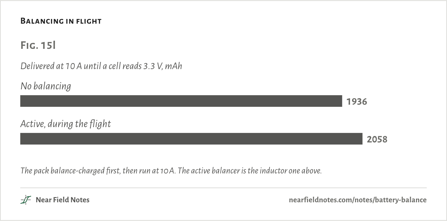
Fast enough, an active balancer can work during a flight. It feeds cell 3 from the others while the pack gives 10 A.

The balanced pack then gives 2058 mAh instead of 1936 mAh before any cell reads 3.3 V, 122 mAh more. A bleed can’t do that, since it only takes charge away.

Balancing in flight
Fig. 15lDelivered at 10 A until a cell reads 3.3 V, mAhNo balancing1936Active, during the flight2058Fig. 15lDelivered at 10 A until a cell reads 3.3 V, mAhNo balancing1936Active, during the flight2058Fig. 15lDelivered at 10 A until a cell reads 3.3 V, mAhNo balancing1936Active, during the flight2058

The pack balance-charged first, then run at 10 A. The active balancer is the inductor one above.

The numbers
In flightDeliveredEnds with
No balancing1936 mAhcell 3 at 3.29 V
Active, during the flight2058 mAhcell 3 at 3.30 V

Which balancer

A key

Key to balancing a pack

Which balancer fits?

  1. 1aThe pack charges on a hobby chargerBalance mode, lead plugged in
  2. 1bIt has its own BMS boardGo to 2
  3. 2aOnly overcharge mattersPassive, like the BQ76920
  4. 2bRun time matters tooGo to 3
  5. 3aCharge has to cross the whole stackInductor or transformer, like the LTC3300
  6. 3bNeighbors only, and slow is fineSwitched capacitor

This pack’s answer is 1a. The Tesla Model S balances with resistors, as in 2a.

Fade a cell yourself

24 charges, every one drawn

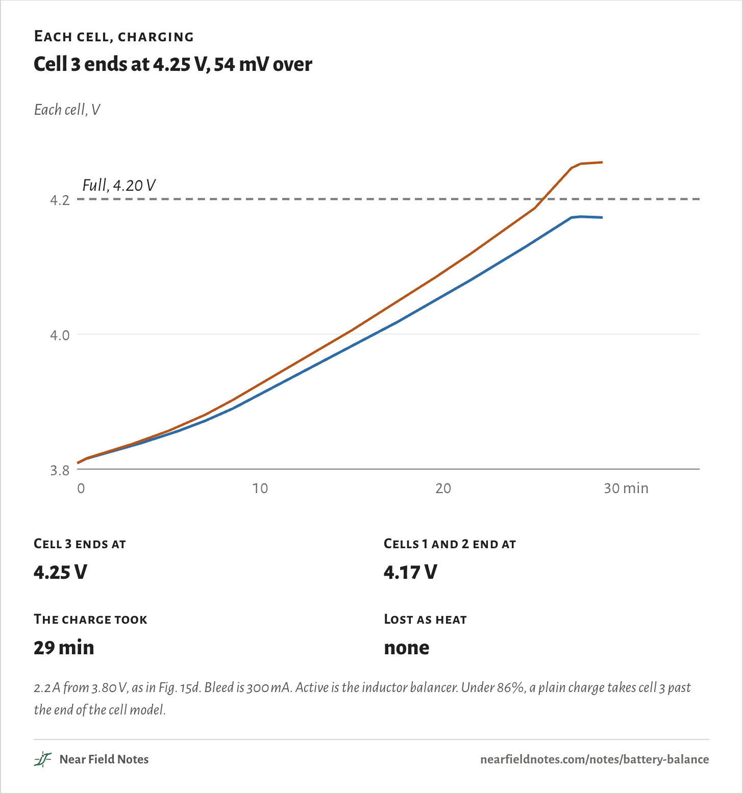
Pick how far cell 3 has faded and how the pack charges. The further it has faded, the further a plain charge takes it past 4.20 V.

A bleed and the active balancer both end with every cell at 4.20 V. The difference is the heat.

90%, 1980 mAh
Charge
Each cell, charging

Cell 3 ends at 4.25 V, 54 mV over

Each cell, V3.84.04.20102030 minFull, 4.20 VEach cell, V3.84.04.20102030 minFull, 4.20 VEach cell, V3.84.04.20102030 minFull, 4.20 V
Cell 3 ends at
4.25 V
Cells 1 and 2 end at
4.17 V
The charge took
29 min
Lost as heat
none

2.2 A from 3.80 V, as in Fig. 15d. Bleed is 300 mA. Active is the inductor balancer. Under 86%, a plain charge takes cell 3 past the end of the cell model.

Every case, as a table
Weak cellChargeWeak cell ends atOthers end atTookLost as heat
100%, 2200 mAhPlain4.20 V4.20 V30 minnone
100%, 2200 mAhBleed 300 mA4.20 V4.20 V30 minnone
100%, 2200 mAhActive4.20 V4.20 V30 minnone
98%, 2156 mAhPlain4.21 V4.19 V29 minnone
98%, 2156 mAhBleed 300 mA4.20 V4.20 V29 min78 mWh
98%, 2156 mAhActive4.20 V4.20 V29 min7 mWh
96%, 2112 mAhPlain4.22 V4.19 V29 minnone
96%, 2112 mAhBleed 300 mA4.20 V4.20 V29 min160 mWh
96%, 2112 mAhActive4.20 V4.20 V29 min13 mWh
94%, 2068 mAhPlain4.23 V4.18 V29 minnone
94%, 2068 mAhBleed 300 mA4.20 V4.20 V29 min244 mWh
94%, 2068 mAhActive4.20 V4.20 V29 min20 mWh
92%, 2024 mAhPlain4.24 V4.18 V29 minnone
92%, 2024 mAhBleed 300 mA4.20 V4.20 V29 min327 mWh
92%, 2024 mAhActive4.20 V4.20 V29 min28 mWh
90%, 1980 mAhPlain4.25 V4.17 V29 minnone
90%, 1980 mAhBleed 300 mA4.20 V4.20 V29 min412 mWh
90%, 1980 mAhActive4.20 V4.20 V29 min35 mWh
88%, 1936 mAhPlain4.26 V4.17 V28 minnone
88%, 1936 mAhBleed 300 mA4.20 V4.20 V29 min497 mWh
88%, 1936 mAhActive4.20 V4.20 V28 min42 mWh
86%, 1892 mAhPlain4.28 V4.16 V28 minnone
86%, 1892 mAhBleed 300 mA4.20 V4.20 V33 min587 mWh
86%, 1892 mAhActive4.20 V4.20 V28 min50 mWh

Conditions

Pack
Three LiPo cells in series, two of 2200 mAh and cell 3 faded to 1980 mAh, all from 3.80 V. Sized like the Gens Ace 2200 mAh 3S 25C, GEA22003S25X6, with a plain label.
Cells
An equivalent circuit for each: the open-circuit voltage of a LiCoO2/graphite pouch cell from PyBaMM’s Ai2020 parameters, then 4 mΩ in series and 2 mΩ in parallel with 10 kF. The resistances and the capacitance are assumed. No LiPo maker publishes them.
Charger
2.2 A until the pack reads 12.60 V, then 12.60 V until the current falls to 220 mA. A balance charge also waits until every cell is within 5 mV.
Bleed
14 Ω, 300 mA at 4.20 V, the SkyRC B6 Evo’s most. The BQ76920 case uses 84 Ω, 50 mA, on 70% of the time. Each bleeds any cell more than 1 mV above the lowest, once the spread passes 3 mV.
Active
0.825 A out of the highest cell, 87.7% of the energy into the lowest, from the inductor balancer’s settled cycle
Balancers
ngspice, cells as sources behind 4 mΩ. Inductor: 10 µH with 20 mΩ, 50 kHz, on 45% of each cycle, an ideal 10 mΩ switch and a diode. Capacitor: 100 µF with 5 mΩ, 10 kHz, 10 mΩ switches.
Flight
10 A, until a cell is empty or, for Fig. 15l, until a cell reads 3.3 V under load
Renders
Blender. Cells, tabs and plugs from the pack’s published size and photos.

Simulated only. Nothing on this page has been measured on a board yet.

Limits

  • Past 4.20 V the cell model extends its fitted curves, so voltages there are indicative.
  • The cells’ resistance is a guess. A higher one would make every cell read higher while charging.
  • One temperature throughout, with no heating and no aging during a run. Self-discharge is left out.
  • Fig. 15e is another cell, 5 Ah, tested in 0.1 V steps. No one has tested 4.25 V.
  • The active balancer’s current is held at its value between cells at 4.10 and 4.00 V.

Files

  • sim/pack.pyThe cell model, charger and balancers
  • sim/scenarios.pyThe charges and flights
  • sim/balancers.pyThe inductor and capacitor balancers in ngspice
  • sim/site.pyThe explorer’s sweep
  • render/scene.pyThe renders
  • refs/research.mdEvery datasheet and paper figure and its source

Sources

Like this note?

Rev 1 ·
  1. Rev 1First published

Each fix gets a line here, with the reader's name if they want credit.

Did it answer your question?

Want more on this?

Report a problem

What should the next note be? Ask for one