It charges a tiny capacitor from the data line while the line is high, and runs on that while the line is low.
That is enough to talk, but not to take a reading. A reading takes up to 1.5 mA. On a 3.3 V board a 4.7 kΩ pull-up can give 64 µA before the pin falls under the 3.0 V the chip needs.
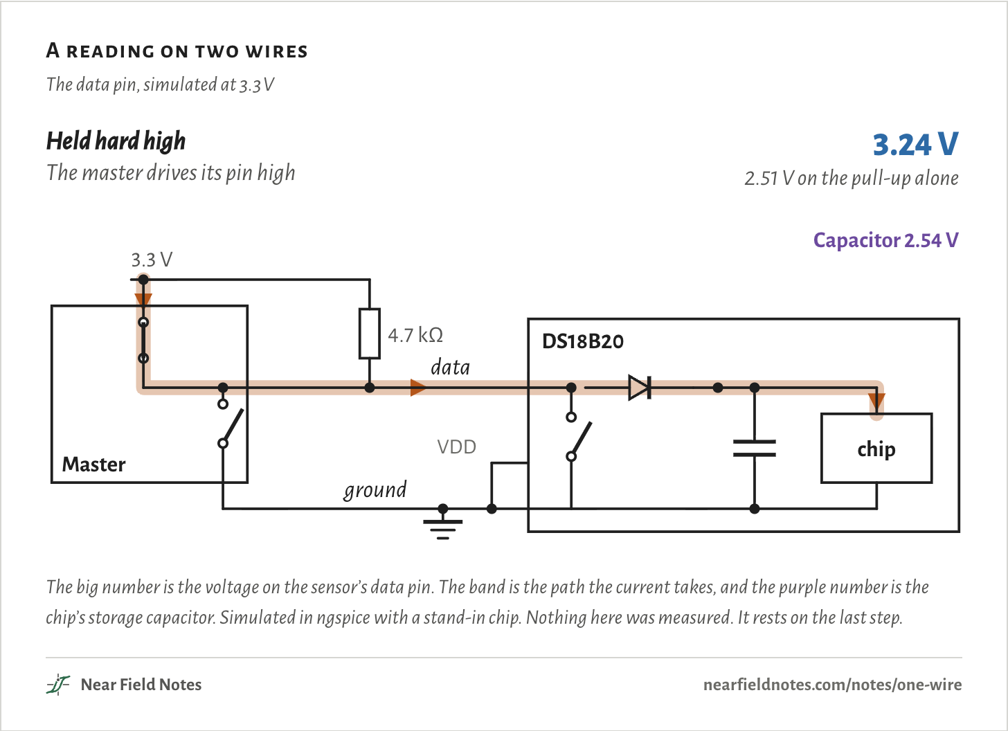
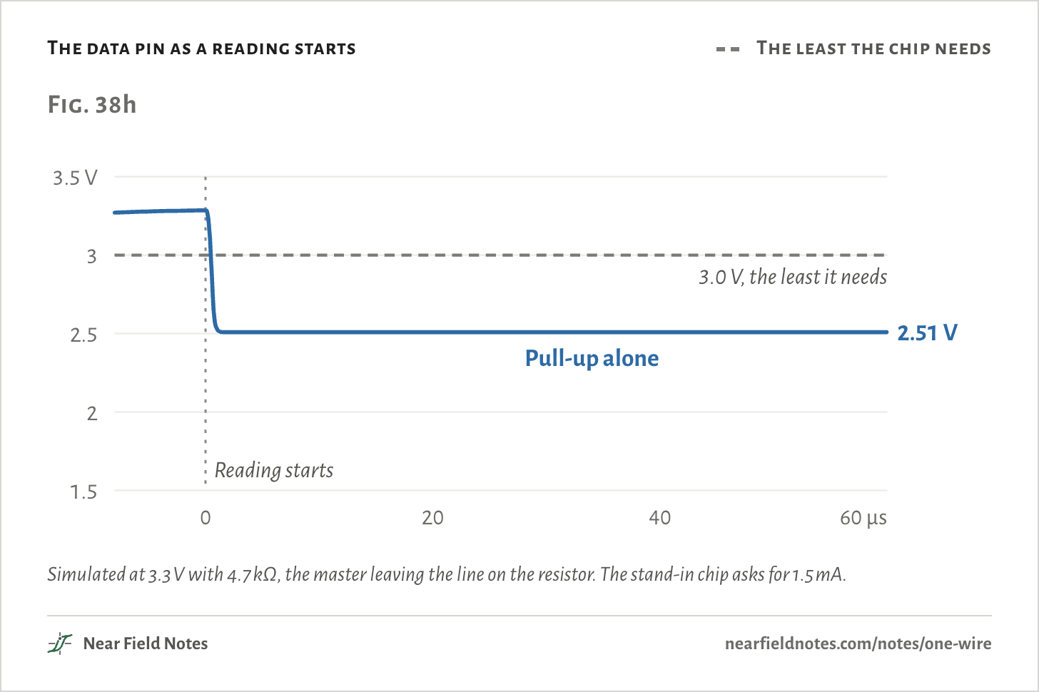
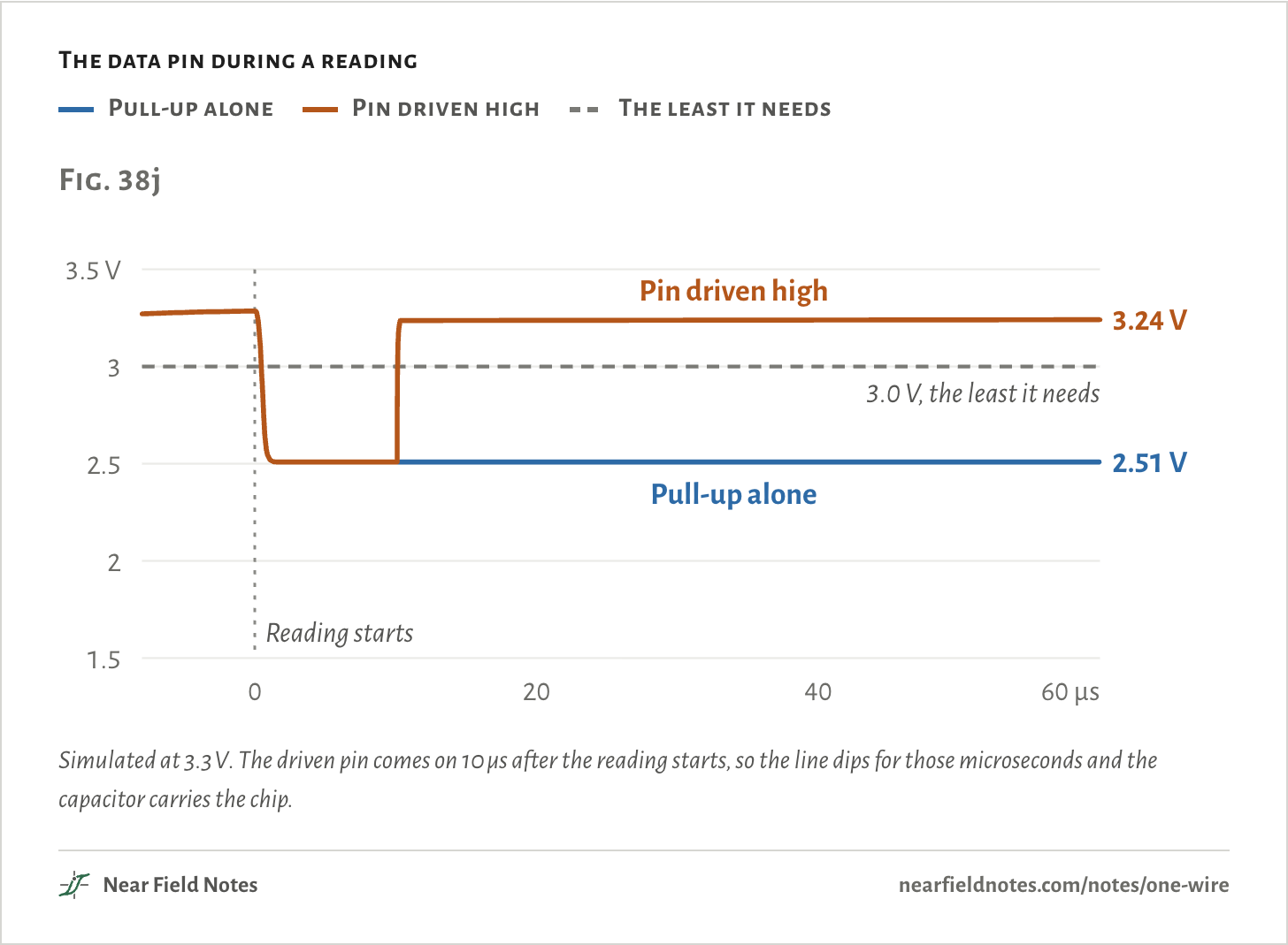
Simulated, the pin sags to 2.51 V. With the master’s own pin driven high, it holds at 3.24 V.
A DS18B20 that loses power partway through a reading resets. Read it back and it says exactly 85 °C, the value it wakes up with.
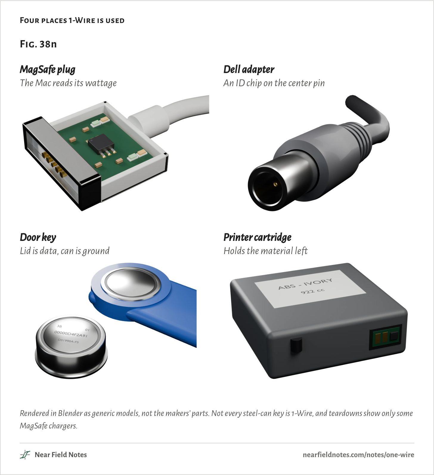
The bus is 1-Wire, Dallas Semiconductor’s from 1989, now Analog Devices’. The same bus is in MagSafe plugs, Dell adapters and steel-can door keys.
A reading on two wires
The data pin, simulated at 3.3 V
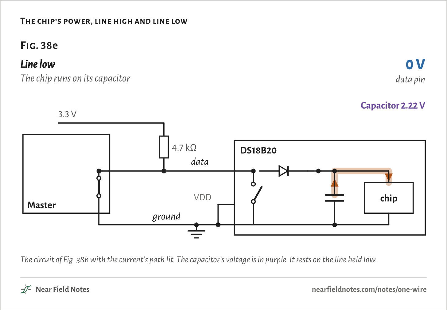
The big number is the voltage on the sensor’s data pin. The band is the path the current takes, and the purple number is the chip’s storage capacitor. Simulated in ngspice with a stand-in chip. Nothing here was measured. It rests on the last step.
A temperature sensor on two wires
DS18B20, 3.3 V
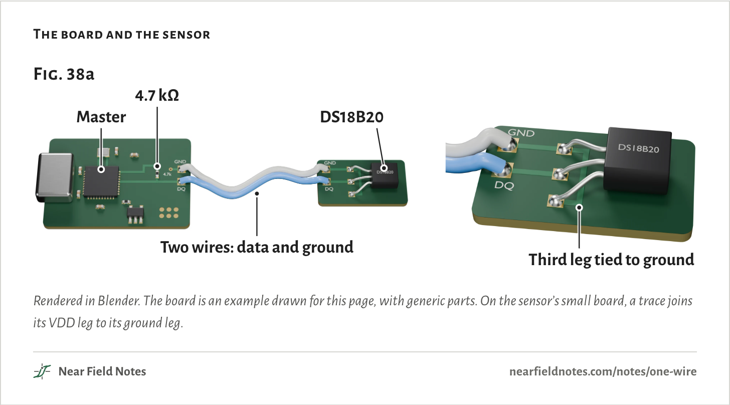
Take a small 3.3 V board with a DS18B20 temperature sensor on a cable. The cable has two wires: ground and data.
A DS18B20 has three legs: ground, data and VDD, its supply. Wired for what Analog Devices calls parasite power, VDD is tied to ground. The chip takes its power from the data line instead.
On the board, a 4.7 kΩ resistor pulls the data line up to 3.3 V.
The board and the sensor
Rendered in Blender. The board is an example drawn for this page, with generic parts. On the sensor’s small board, a trace joins its VDD leg to its ground leg.
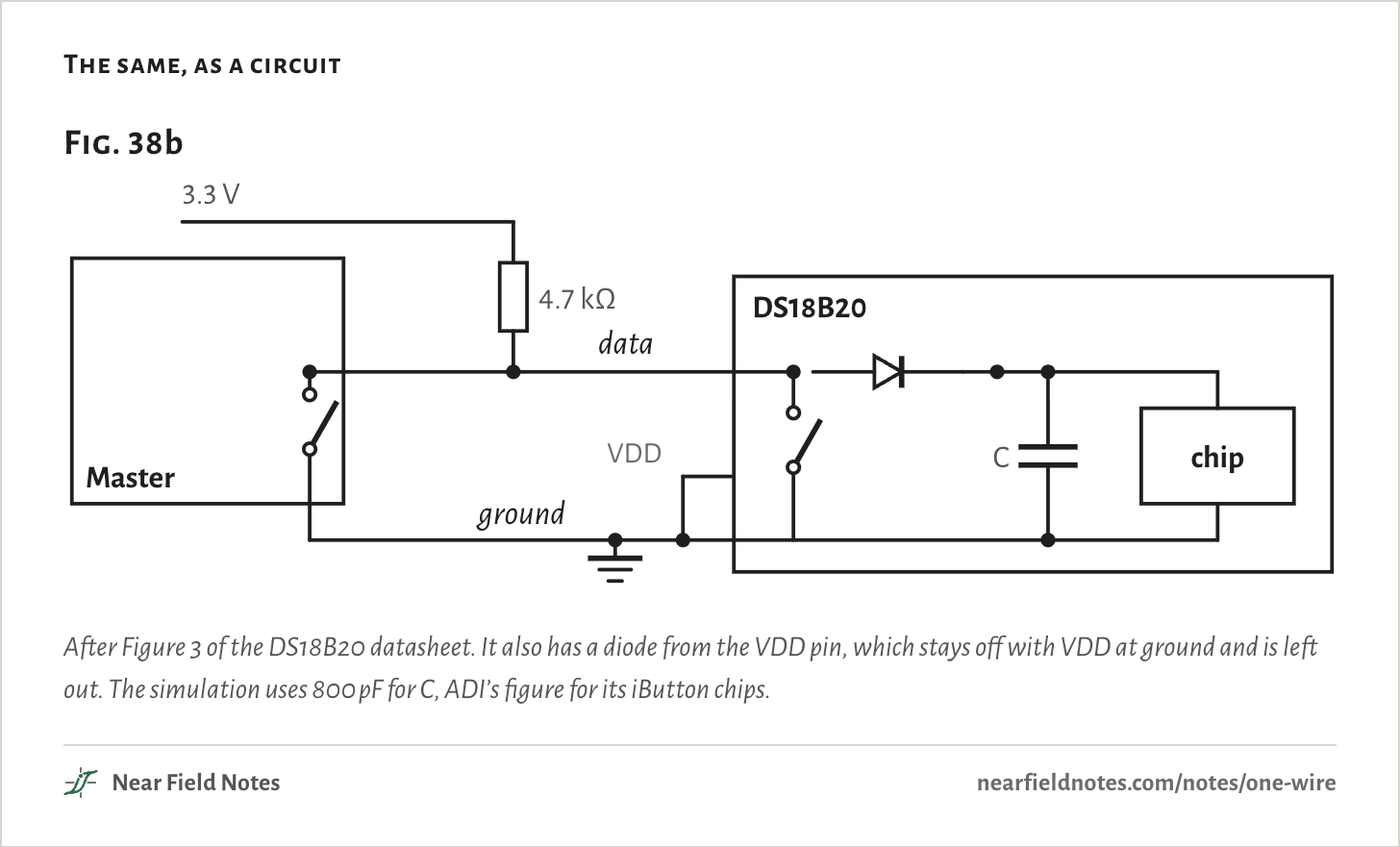
As a circuit, nothing drives the line high. The master and the sensor can each pull it low through a switch, and the resistor brings it back up. That is an open-drain bus, the same idea as I2C in Note 24.
Inside the sensor, a diode runs from the data pin to a capacitor, and the capacitor feeds the chip. The datasheet calls the capacitor CPP and doesn’t give its size.
The same, as a circuit
After Figure 3 of the DS18B20 datasheet. It also has a diode from the VDD pin, which stays off with VDD at ground and is left out. The simulation uses 800 pF for C, ADI’s figure for its iButton chips.
A bit is a timed low pulse
70 µs a slot
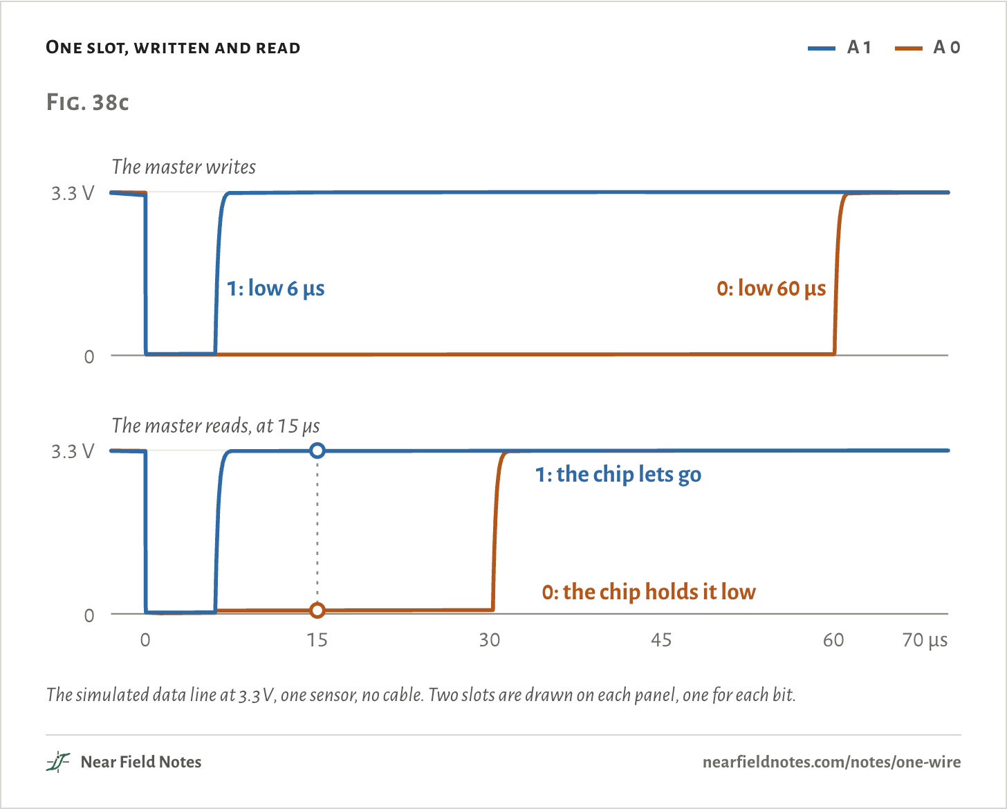
Every bit starts with the master pulling the line low. How long it holds it says what the bit is. A short low is a 1 and a long one is a 0.
To read, the master pulls the line low for a moment and lets go. A sensor sending a 1 does nothing, so the line climbs back up. A sensor sending a 0 holds it low. The master looks at 15 µs. In the simulation the line is at 3.29 V for a 1 and 0.07 V for a 0.
The sensor’s own clock may be off by a factor of four, so it samples anywhere from 15 to 60 µs after the edge. The long slots allow for that. ADI puts the speed at 15.4 kbit/s.
One slot, written and read
A 1
A 0
The simulated data line at 3.3 V, one sensor, no cable. Two slots are drawn on each panel, one for each bit.The numbers
3.3 V, 4.7 kΩ, one sensor, no cable. Each slot is 70 µs.
Slot
The line
At 15 µs
Write 1
6.2 µs low
—
Write 0
60.2 µs low
—
Read 1
6 µs low, then let go
3.29 V
Read 0
Held low by the chip
0.07 V
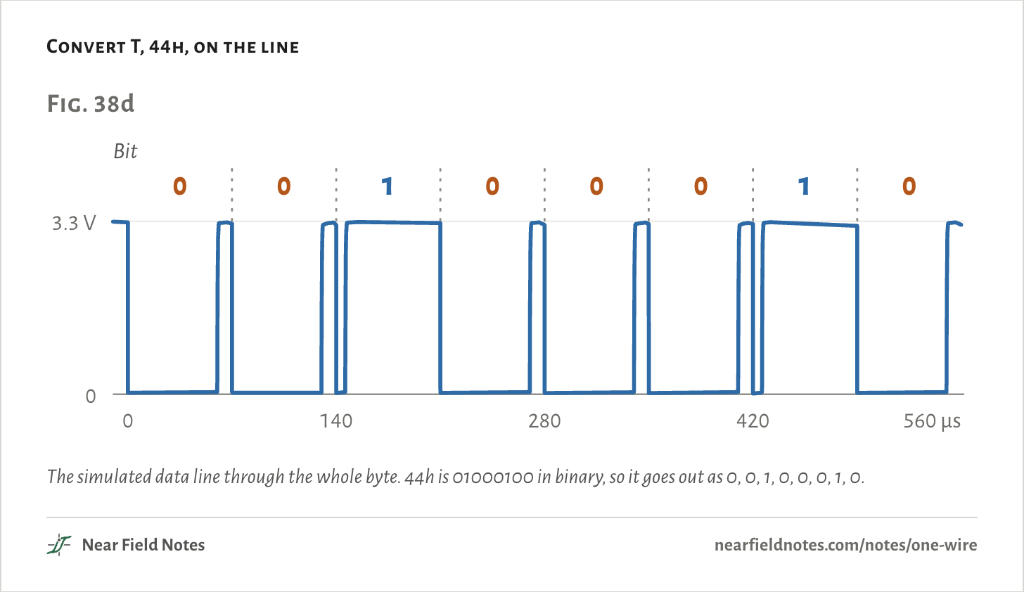
A command is eight slots, lowest bit first. Convert T, the command that starts a temperature reading, is 44 in hex.
Ahead of every command the master holds the line low for 480 µs, a reset. Each sensor answers with a low pulse of its own to say it is there, a presence pulse.
Convert T, 44h, on the line
The simulated data line through the whole byte. 44h is 01000100 in binary, so it goes out as 0, 0, 1, 0, 0, 0, 1, 0.
Power from the data line
0.60 V in a reset
While the line is high, current runs through the pull-up and the diode and charges the capacitor. In the simulation it sits at 2.82 V, a diode drop under the pin.
While the line is low, the diode blocks and the chip runs on the capacitor alone. Asleep, a DS18B20 draws 750 nA typical and 1 µA at most.
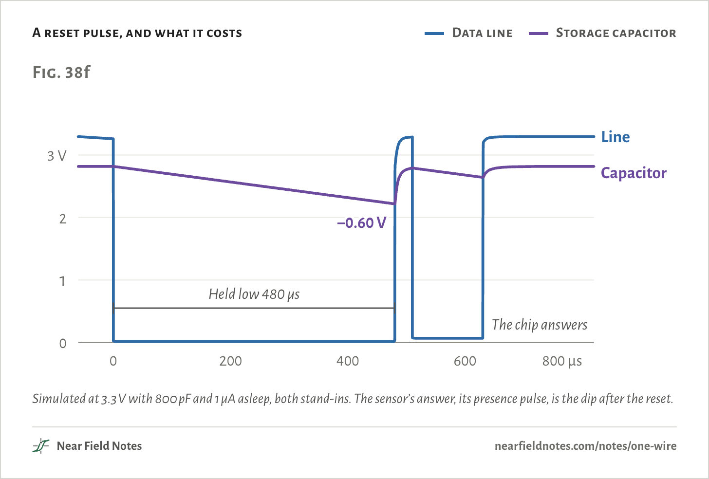
A short slot costs it little. The longest low is the reset, 480 µs. At 1 µA from 800 pF, that takes the capacitor down 0.60 V, to 2.22 V. It is just the current times the time over the capacitance: 1 µA × 480 µs ÷ 800 pF.
The chip’s power, line high and line low
The circuit of Fig. 38b with the current’s path lit. The capacitor’s voltage is in purple. It rests on the line held low.
The capacitor charges back in about 20 µs once the line goes high, and the chip answers the reset.
There is room, but not a lot. The datasheet warns that under parasite power a reset low for more than 960 µs can reset the chip.
Twice the time is twice the drop: 960 µs takes the capacitor down 1.20 V. The supply voltage doesn’t change that. The drop is only the current times the time over the capacitance.
A reset pulse, and what it costs
Data line
Storage capacitor
Simulated at 3.3 V with 800 pF and 1 µA asleep, both stand-ins. The sensor’s answer, its presence pulse, is the dip after the reset.The numbers
3.3 V, 4.7 kΩ, an 800 pF storage capacitor and 1 µA standby, both stand-ins. The drop is the current times the time over the capacitance, so the supply hardly changes it.
Simulated
Capacitor before
2.819 V
Capacitor, end of the 480 µs low
2.219 V
Drop, 1 µA standby
0.600 V
Drop, 750 nA standby, 5 V run
0.451 V
Drop, a 960 µs low, 1 µA, 5 V run
1.200 V
Back within 50 mV after
20.3 µs
A reading takes more than the line can give
1.5 mA wanted, 64 µA there
Talking is cheap. A temperature reading isn’t. While it converts, a DS18B20 draws 1 mA typical and 1.5 mA at most, for up to 750 ms at 12 bits.
The capacitor can’t carry that. At 2.82 V, 800 pF holds about 2.3 nC. A reading at 1 mA for 750 ms uses 750 µC, some 300,000 times as much. The reading has to run on the pull-up.
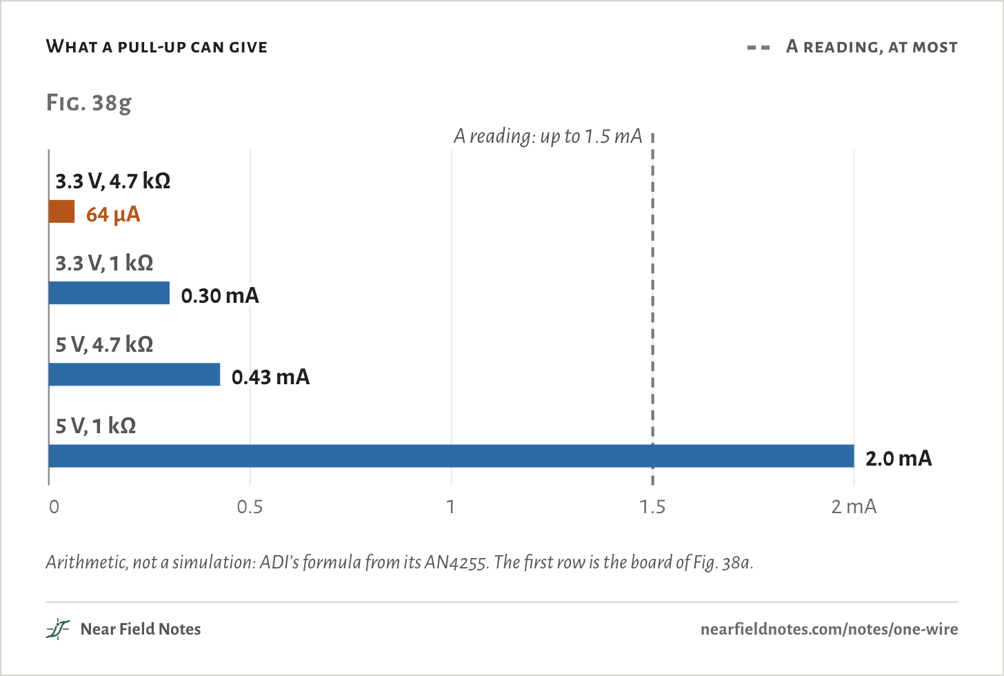
In parasite mode the chip needs at least 3.0 V on its pin. ADI’s formula for what a pull-up can give before the pin falls under that is the supply minus 3.0 V, over the resistor. At 3.3 V that leaves 0.3 V across 4.7 kΩ: 64 µA.
What a pull-up can give
A reading, at most
Arithmetic, not a simulation: ADI’s formula from its AN4255. The first row is the board of Fig. 38a.The numbers
ADI AN4255’s formula. A DS18B20 draws 1 mA typical and 1.5 mA at most while it converts.
Pull-up
Sum
Current
3.3 V, 4.7 kΩ
(3.3 − 3) V / 4.7 kΩ
64 µA
3.3 V, 1 kΩ
(3.3 − 3) V / 1 kΩ
300 µA
5 V, 4.7 kΩ
(5 − 3) V / 4.7 kΩ
426 µA
5 V, 1 kΩ
(5 − 3) V / 1 kΩ
2000 µA
Simulated on the pull-up alone, the pin falls through 3.0 V as soon as the reading starts and settles at 2.51 V. The chip gets 0.17 mA of the 1.5 mA it asks for.
Where the pin settles depends on the model: on where the chip stops drawing current, which no datasheet gives. What doesn’t depend on the model is that it ends up under 3.0 V.
At 5 V the same resistor gives 0.43 mA, and one sensor at 5 V on 4.7 kΩ often works. In one forum test, a parasite sensor on 4.7 kΩ passed at 5 V and failed at 3.3 V. Those results fit chips that draw only 0.3 to 0.5 mA, less than the datasheet’s 1 mA typical. A stand-in chip that keeps drawing 0.3 mA holds the pin at 3.59 V at 5 V, and drags it to 1.89 V at 3.3 V.
The data pin as a reading starts
The least the chip needs
Simulated at 3.3 V with 4.7 kΩ, the master leaving the line on the resistor. The stand-in chip asks for 1.5 mA.The numbers
3.3 V, 4.7 kΩ, a stand-in chip asking for 1.5 mA. Where it settles depends on the model.
Simulated
Before the reading
3.30 V
Settles at
2.51 V
Capacitor settles at
1.90 V
The chip gets
0.17 mA
Four ways to a wrong reading
Fig. 38i
What happened
Reads
Evidence
The chip loses power and resets
85.00 °C
The power-on value, 0550h. Its register starts there
The master reads before the reading ends
85.00 °C
Read at 590 ms: 85.00. At 591 ms: 21.37
Any glitch on its supply, then a read
85.00 °C
A 400 µs dropout set about half of 53 sensors to it
The chip is starved but doesn’t reset
127.94 °C
07FFh, on genuine parts
The power-on value is from the DS18B20 datasheet. The other rows are published bench tests: the reads at 590 and 591 ms on an owfs list, the dropout on a 53-sensor bus with its own supply, and 127.94 °C from Chris Petrich’s tests. All are listed under Sources.
612
The 85 °C reading
Exactly 85.00 °C
Field marks. A reading of exactly 85.00 °C. It is the value in the temperature register at power-on, 0550h. A chip that loses power partway through a reading resets, and hands it back.
Look-alike. A real 85 °C. It is a legal temperature, so a reading of 85 proves nothing alone. Chris Petrich found the two differ in byte 6 of the scratchpad, the memory the master reads the temperature from: 0Ch after power-on and 10h after a real reading. ADI doesn’t document it.
Range. Starved but not reset, a genuine chip reads 127.94 °C instead. A read that comes too soon gives 85.00 too, on any supply: in one test a read at 590 ms gave 85.00 and one at 591 ms gave 21.37 °C.
Habitat.3.3 V boards whose master leaves the line on the resistor during a reading. Reported cases include owserver on a Raspberry Pi, an I2C-to-1-Wire bridge set not to drive the line high, and a level shifter in the line.
613
Hold the line hard high
3.24 V with the pin driven
The datasheet’s fix is a strong pull-up. Something has to connect the line straight to the supply “within 10µs (max)” of the command, hold it there for the whole reading, and keep everything else off the bus meanwhile.
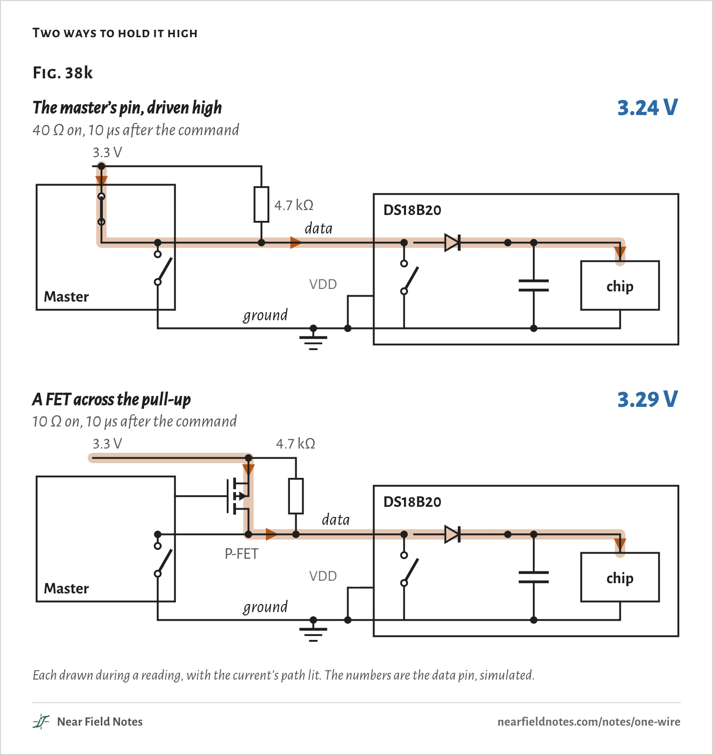
The simplest is the master’s own pin, switched from open-drain to driven high. In the simulation, a 40 Ω pin turned on 10 µs after the command holds the line at 3.24 V. The chip gets its full 1.5 mA.
A P-channel MOSFET from the supply to the line does the same, with a master pin working its gate: 3.29 V.
The data pin during a reading
Pull-up alone
Pin driven high
The least it needs
Simulated at 3.3 V. The driven pin comes on 10 µs after the reading starts, so the line dips for those microseconds and the capacitor carries the chip.The numbers
3.3 V. The pin or the FET turns on 10 µs after the reading starts.
Way
Data pin
Capacitor
Chip gets
Pull-up alone
2.51 V
1.90 V
0.17 mA
Master’s pin driven high, 40 Ω
3.24 V
2.54 V
1.5 mA
FET across the pull-up, 10 Ω
3.29 V
2.59 V
1.5 mA
On an Arduino this is already done. The OneWire library’s write takes a power flag, as in ds.write(0x44, 1), that leaves the pin driven high after the byte. The DallasTemperature library sets it when it finds a parasite sensor, and the Linux kernel driver drives the line high too.
Reported failures cluster on 3.3 V hosts that don’t, which is how one sensor can work on one board and read 85 °C on another.
The other way out is the third wire. With VDD on a supply, the chip draws its reading from there and the line only carries data.
Two ways to hold it high
Each drawn during a reading, with the current’s path lit. The numbers are the data pin, simulated.
Finding every chip on the line
13 ms a chip
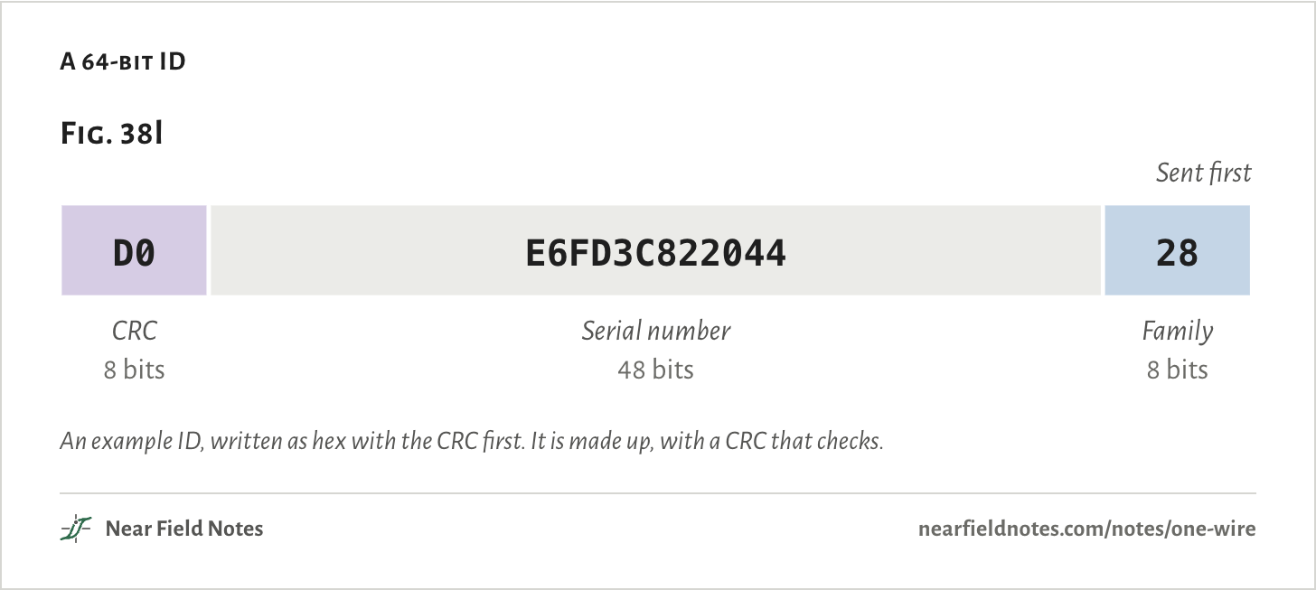
One line can carry many sensors, so the master needs to tell them apart. Each chip has a 64-bit ID set at the factory.
The last 8 bits, sent first, are the family code: 28 for a DS18B20. Then 48 bits of serial number, then a CRC, a check code worked out from the other 56 bits. The chip never checks it. The master has to.
A 64-bit ID
An example ID, written as hex with the CRC first. It is made up, with a CRC that checks.
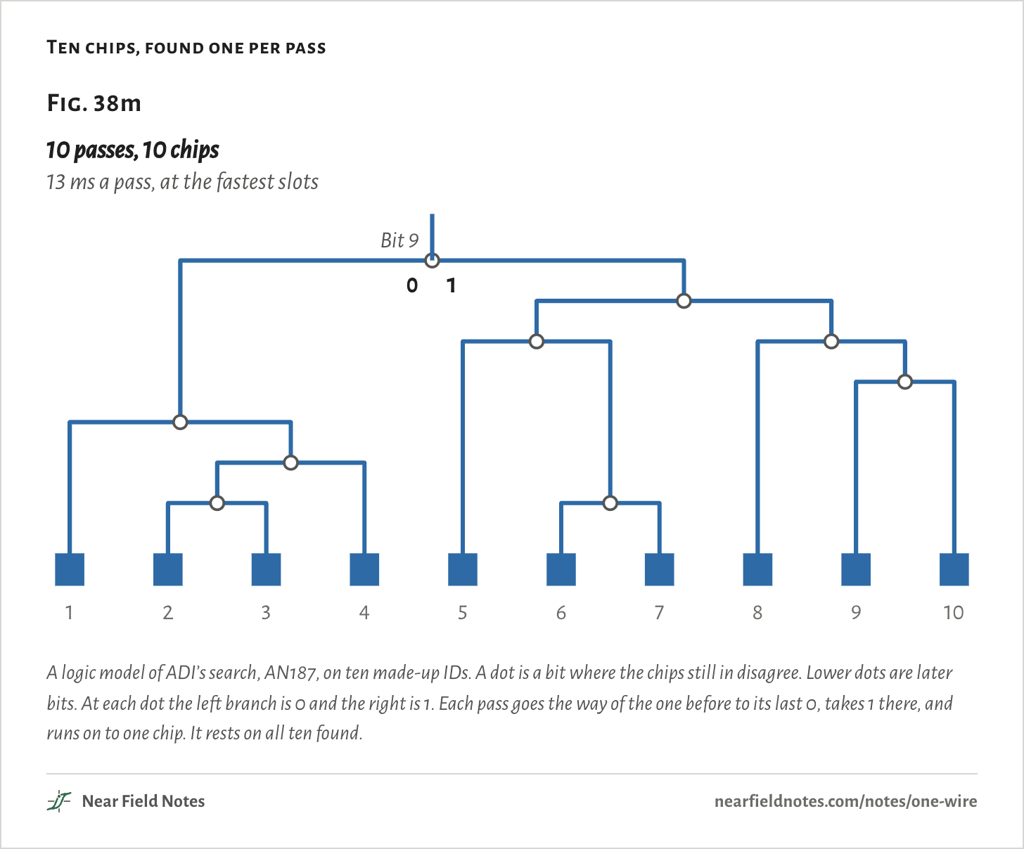
To learn the IDs, the master runs a search. Every chip answers every bit at once, on the same wire. For each bit the master reads the bit, then its opposite, then writes the value it picks.
The master reads
It means
0 then 1
Every chip still in has a 0
1 then 0
Every chip still in has a 1
0 then 0
They disagree. The master picks a side
1 then 1
No chip answered
At a 0 then 0 the master picks a side, and the chips on the other side drop out until the next pass. Each pass finds one chip.
A pass is a reset, the command and three slots for each of the 64 bits: 200 slots, 13.16 ms at the shortest timing allowed. ADI gives the same figure, “up to 75 different iButtons per second”.
Ten chips, found one per pass
A logic model of ADI’s search, AN187, on ten made-up IDs. A dot is a bit where the chips still in disagree. Lower dots are later bits. At each dot the left branch is 0 and the right is 1. Each pass goes the way of the one before to its last 0, takes 1 there, and runs on to one chip. It rests on all ten found.The numbers
Ten made-up IDs, family 28. A pass is 200 slots: 13.16 ms at the shortest legal slot, 14.96 ms at ADI’s usual software timing.
Pass
ID found, CRC first
Forks met at bits
1
D0 E6FD3C822044 28
9, 13
2
44 975F33D50B94 28
9, 13, 14, 15
3
2E E02CBFBB58D4 28
9, 13, 14, 15
4
2C 040D0B0FA234 28
9, 13, 14
5
14 0EF9306BC2F1 28
9, 10, 11
6
8B 919B61D8AA3D 28
9, 10, 11, 15
7
CA EB7076B077FD 28
9, 10, 11, 15
8
19 E0710ED86EC3 28
9, 10, 11
9
FE 7588E401DDC7 28
9, 10, 11, 12
10
B8 CE7CF511C9FF 28
9, 10, 11, 12
Where the bus hides
Plugs, keys and cartridges
Ken Shirriff’s teardowns found a 1-Wire chip in the MagSafe plug. Its ID carries the charger’s wattage, and its two outputs light the plug’s orange and green LEDs. The Mac, not the charger, picks the color. The chip answers like ADI’s DS2413 switch, though no marking was read.
Dell’s barrel adapters carry a Dallas memory on the center pin. Published dumps hold plain text like DELL00AC090195046, with 090 for 90 W and 195 for 19.5 V. If the laptop can’t read it, the laptop still runs, but it may not charge its battery and it slows its processor.
An iButton is a 1-Wire chip in a 16 mm steel can, with the lid for data and the can for ground: truly two contacts. The DS1990A kind is the door and intercom key. Maxim counted over 350 million iButtons in use in 2014.
Stratasys 3D-printer cartridges hold a DS2433 1-Wire memory that keeps track of the material left. The printer turns away an empty one.
Four places 1-Wire is used
Rendered in Blender as generic models, not the makers’ parts. Not every steel-can key is 1-Wire, and teardowns show only some MagSafe chargers.
How long a line?
About 63 m on 4.7 kΩ
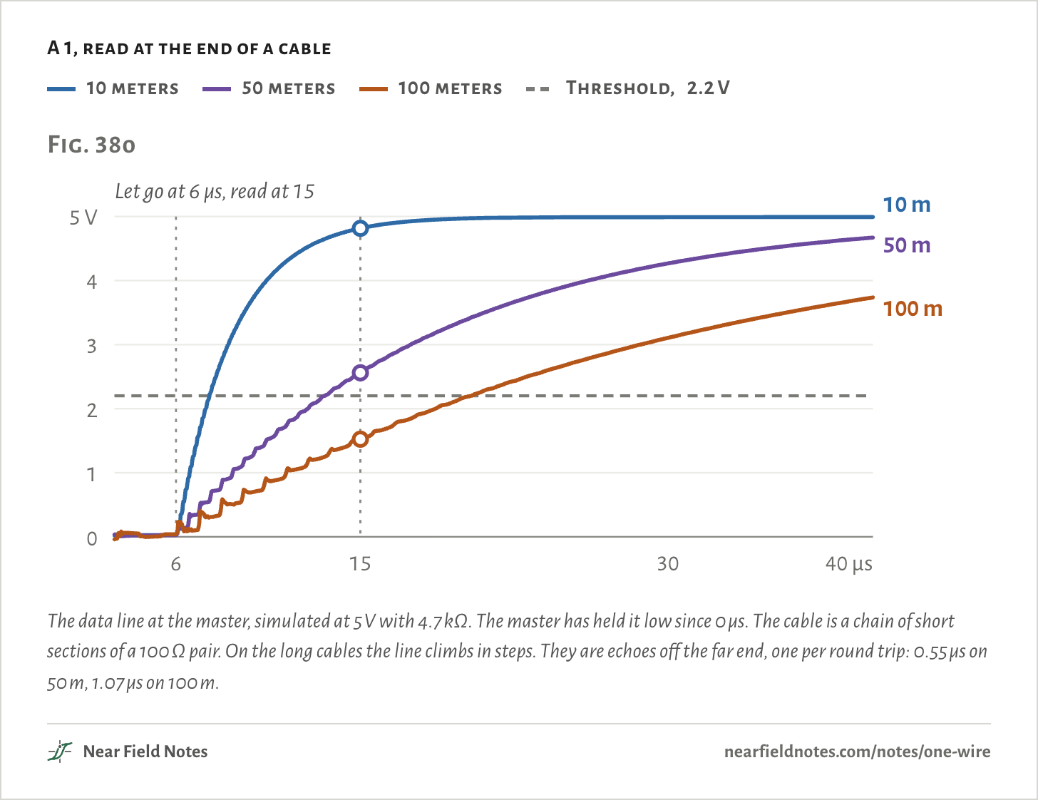
A long cable puts capacitance on the line. In a read slot the master lets go at 6 µs and reads at 15 µs. In those 9 µs the pull-up has to charge the cable back above 2.2 V, the level a 1 has to clear.
Simulated at 5 V, with Cat 5e’s 52 pF per meter and one sensor at the far end, the line at 15 µs is 4.82 V after 10 m and 2.56 V after 50 m. After 100 m it is 1.52 V, and the master reads the 1 as a 0.
A 1, read at the end of a cable
10 meters
50 meters
100 meters
Threshold, 2.2 V
The data line at the master, simulated at 5 V with 4.7 kΩ. The master has held it low since 0 µs. The cable is a chain of short sections of a 100 Ω pair. On the long cables the line climbs in steps. They are echoes off the far end, one per round trip: 0.55 µs on 50 m, 1.07 µs on 100 m.The numbers
5 V bus, 4.7 kΩ, 52 pF/m, the cable as a chain of 2 m sections. Step every: measured on the simulated rise. Round trip: twice the length at the cable’s 5.2 ns per meter. At 200 m the steps come every 2.122 µs.
Cable
At 15 µs
Read as
Step every
Round trip
10 m
4.82 V
1
0.126 µs
0.104 µs
50 m
2.56 V
1
0.546 µs
0.520 µs
100 m
1.52 V
0, wrongly
1.072 µs
1.040 µs
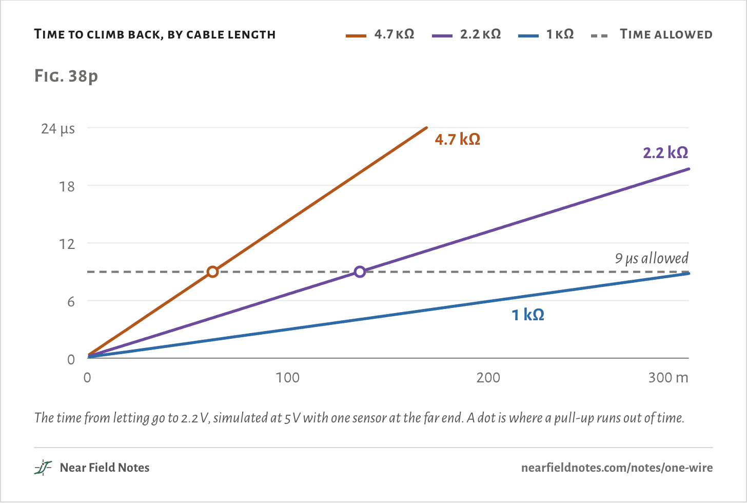
A smaller pull-up charges the cable faster. The climb takes longer than 9 µs past about 63 m with 4.7 kΩ and about 136 m with 2.2 kΩ. With 1 kΩ it still makes it at 300 m, in 8.8 µs. ADI reported 300 m working with 1.0 kΩ in 1997.
That is the rise time alone. Hobby reports put a 4.7 kΩ pull-up on a bare microcontroller pin at 10 to 20 m before it gets flaky, for other reasons such as hard edges and star wiring. ADI gives a bare port pin about 3 m.
Time to climb back, by cable length
4.7 kΩ
2.2 kΩ
1 kΩ
Time allowed
The time from letting go to 2.2 V, simulated at 5 V with one sensor at the far end. A dot is where a pull-up runs out of time.The numbers
Microseconds to 2.2 V, 5 V bus, 52 pF/m. Bold: past the 9 µs allowed. The cable as one lumped capacitor; a ladder of short sections lands within 8%.
Pull-up
10 m
30 m
50 m
100 m
200 m
300 m
Limit
4.7 kΩ
1.6
4.4
7.2
14.3
28.3
42.4
63 m
2.2 kΩ
0.8
2.1
3.4
6.7
13.2
19.7
136 m
1 kΩ
0.4
1.0
1.5
3.0
5.9
8.8
over 300 m
Will it read?
Three questions
Whether a DS18B20 on a data line gets through a reading comes down to how it is powered, what the master does during the reading, and the bus voltage.
Key to a DS18B20 that has to take a reading
Does it need a strong pull-up?
1aVDD is wired to a supplyNo, it draws from VDD
1bVDD is tied to groundGo to 2
2aThe master drives its pin high for the readingIt already has one
2bThe master leaves the line on the resistorGo to 3
3aThe bus is 5 V, one sensor, 4.7 kΩOften works. Add one anyway
3bThe bus is 3.3 VYes, it needs one
The board in Fig. 38a ends at 3b if its master leaves the line on the resistor. Driving the pin high, as Arduino’s OneWire library does with its power flag set, moves it to 2a.
Conditions
Simulated
Every voltage, current and time on the bus comes from a circuit simulation. None was measured.
Circuit
A 3.3 V supply and a 4.7 kΩ pull-up to the data line, with 30 pF for the master’s pin and a few centimeters of trace. The master pulls low through 20 Ω, the sensor through 100 Ω. One sensor, no cable, unless a figure says otherwise.
Sensor
A stand-in: a generic diode from the pin, 0.5 V at 1 µA and 0.7 V at 1.5 mA, into an 800 pF capacitor. It draws 1 µA asleep and 1.5 mA converting, from a load that fades out below 2.0 V on the capacitor. Its replies are scripted. It has no reset.
Strong pull-up
The master’s pin driven high through 40 Ω, or a FET of 10 Ω, each turned on 10 µs after Convert T.
Timing
70 µs slots. A 1 is about 6 µs low and a 0 about 60 µs. A read: low for 6 µs, sampled at 15 µs. A reset: 480 µs low.
Cable
5 V supply. Cat 5e as a 100 Ω pair with 52 pF per meter, ADI’s figure, as a chain of 2 m sections, or as one capacitor for the rise times. The two give rise times within 8%.
Search
A logic model of the search in ADI’s AN187 on ten made-up IDs, family 28. Slot times from ADI’s AN937 and its recommended software timing.
Solver
ngspice, 269 transient runs.
Render
Blender. The boards and the products are generic models drawn for this page.
Simulated only. Nothing on this page has been measured on a board.
Limits
The DS18B20’s storage capacitor, its diode drop and the voltage where it resets aren’t published. 800 pF is ADI’s iButton figure. The DS2401 lists 800 pF, the DS2431 1000 pF and the DS28E05 1500 pF.
Where the pin parks during a reading depends on the stand-in load: 2.51 V as drawn, 1.1 V if the load never lets go.
The model switches the reading’s current on in 0.5 µs. A real chip may ramp it, and the datasheet’s 10 µs allowance suggests it does.
The simulation shows the sag, not the 85 °C. It has no reset in it.
This is a 3.3 V story. At 5 V one sensor on 4.7 kΩ often works.
The cable limits are rise time alone, with one sensor. Star wiring, many sensors and hard edges cut them short.
Chris Petrich found every DS18B20 he bought on eBay and AliExpress in 2019 counterfeit. His most common bare clone can’t run on parasite power at all.
Files
sim/onewire.pyThe ngspice circuit and its 269 runs: the whole exchange, the strong pull-ups, the reset, the cable
sim/search.pyThe logic model of the search, its ten IDs and its slot times
render/scene.pyThe boards and the four products in Blender