They differ in which way current can flow through the output, and at which polarity. A 1-quadrant supply only pushes current out at positive voltage, a 2-quadrant one can also take it back, and a 4-quadrant one does both at either polarity. You need more than one quadrant only when your load gives power back or its voltage has to cross zero.
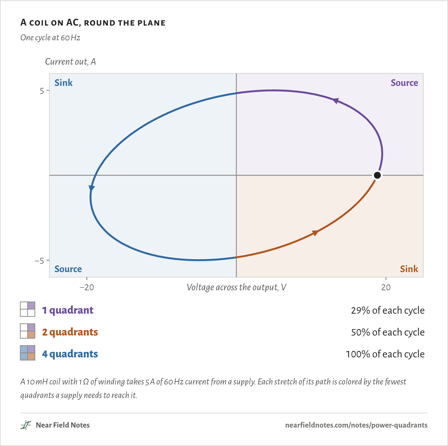
The figure drives a coil with AC. Its voltage leads its current by 75°, so for part of each cycle the coil hands back the energy it stored, and the supply has to take it.
A 1-quadrant supply reaches the coil’s path for 29% of each cycle, a 2-quadrant one for 50%. Only a 4-quadrant supply follows all of it.
A coil on AC, round the plane
One cycle at 60 Hz
A 10 mH coil with 1 Ω of winding takes 5 A of 60 Hz current from a supply. Each stretch of its path is colored by the fewest quadrants a supply needs to reach it.The numbers
A 10 mH coil with 1 Ω of winding on 5 A of 60 Hz current. Its voltage leads its current by 75°.
Quadrant
The supply
Share of each cycle
Fewest a supply needs
Quadrant 1
Source
29%
1 quadrant
Quadrant 2
Sink
21%
4 quadrants
Quadrant 3
Source
29%
4 quadrants
Quadrant 4
Sink
21%
2 quadrants
Three kinds of supply
Simplified output stages
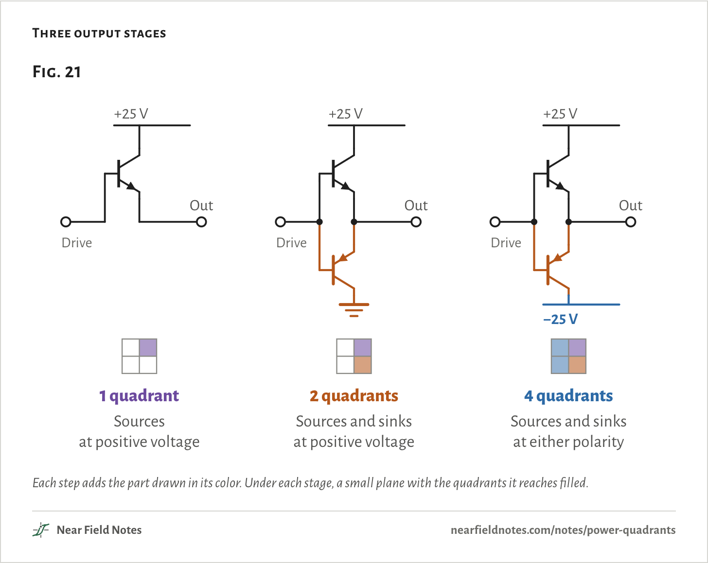
Every supply ends in an output stage, and the stage decides where the output can go. These are linear stages, drawn with only the parts that set the quadrants.
A bench supply has one transistor between its positive rail and the output. It can push current out, and that’s all it can do.
A 2-quadrant supply adds a second transistor that pulls the output down to ground, so current can flow back in.
A 4-quadrant supply returns that transistor to a negative rail. Now the output can swing below zero as well, with current flowing either way.
Three output stages
Each step adds the part drawn in its color. Under each stage, a small plane with the quadrants it reaches filled.The numbers
Stage
Output transistors
Does
Quadrants
1 quadrant
+25 V rail, one npn transistor to the output
Sources at positive voltage
1
2 quadrants
Adds a pnp transistor from the output to ground
Sources and sinks at positive voltage
1 and 4
4 quadrants
Returns that pnp transistor to a −25 V rail
Sources and sinks at either polarity
1 to 4
The voltage-current plane
Where an output can be
Plot the voltage across a supply’s output against the current out of its + terminal. At any moment the output sits at one point on that plane, and the power it gives is the product of the two:
P=VI
=20 V×(−5 A)=−100 W
That point is 20 V with 5 A flowing back in. P is negative, so the supply takes 100 W. A supply sources where P is positive, giving power to the load. It sinks where P is negative, taking power from it.
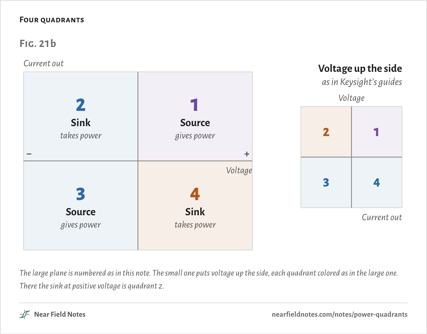
This note puts voltage along the bottom, as Keithley’s 2460 datasheet does, and counts the quadrants counterclockwise from the top right. Keysight’s guides put voltage up the side, so their quadrant 2 is this note’s quadrant 4. Source and sink mean the same in both.
Four quadrants
The large plane is numbered as in this note. The small one puts voltage up the side, each quadrant colored as in the large one. There the sink at positive voltage is quadrant 2.The numbers
Quadrant here
Voltage
Current
The supply
With voltage up the side
1
+
Out
Source, gives power
1
2
−
Out
Sink, takes power
4
3
−
In
Source, gives power
3
4
+
In
Sink, takes power
2
1 quadrant: current goes one way
A braking motor on a 24 V supply
A bench supply’s transistor can only push current out of the positive rail. That works until the load pushes current back. A braking motor does. It turns its motion back into current.
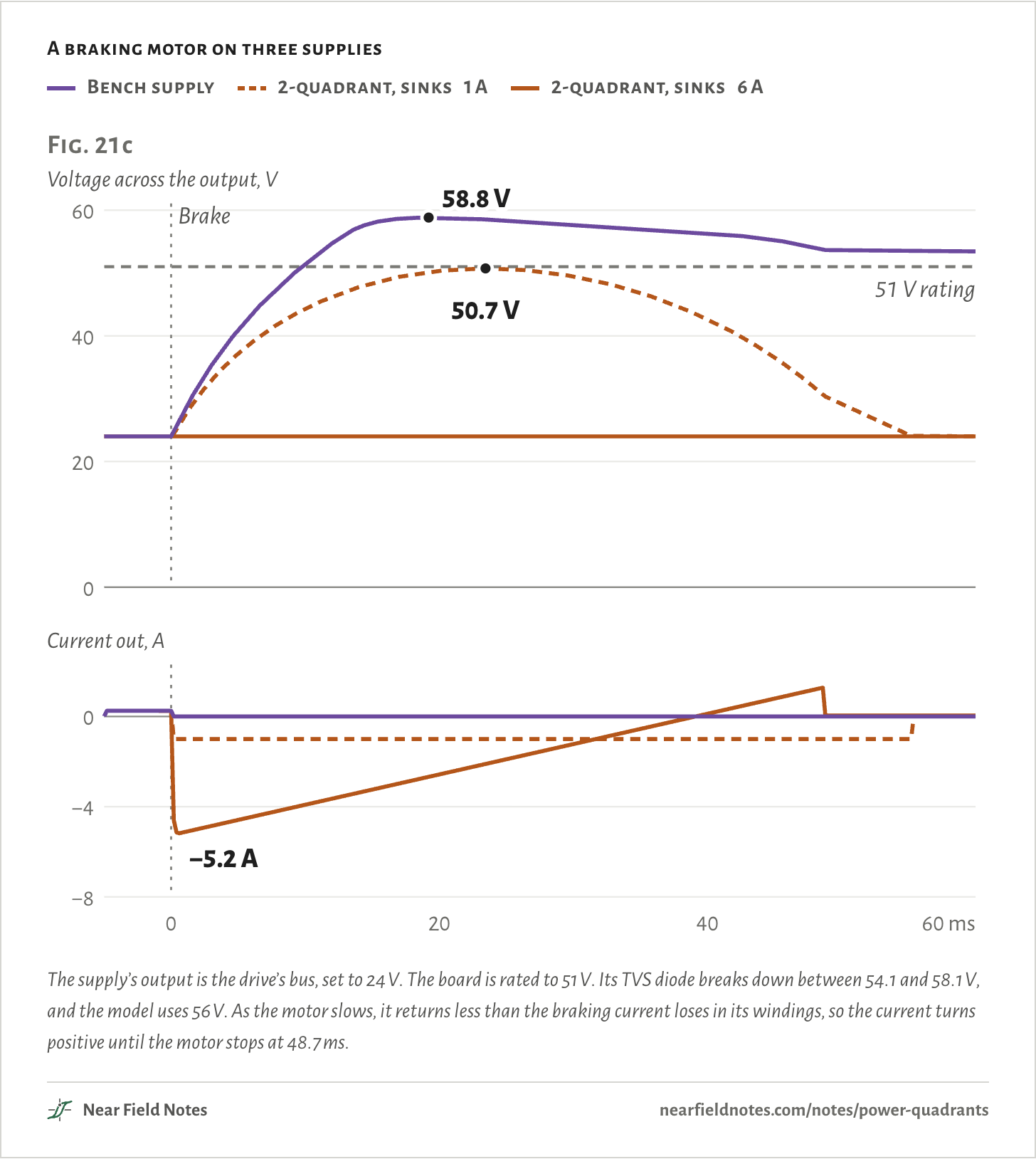
With nowhere to go, that current charges every capacitor on the output, and the voltage climbs until something gives. Here moteus-c1, the motor drive in Note 20, brakes a motor from 3,000 rpm on a 24 V supply.
A braking motor on three supplies
Bench supply
2-quadrant, sinks 1 A
2-quadrant, sinks 6 A
The supply’s output is the drive’s bus, set to 24 V. The board is rated to 51 V. Its TVS diode breaks down between 54.1 and 58.1 V, and the model uses 56 V. As the motor slows, it returns less than the braking current loses in its windings, so the current turns positive until the motor stops at 48.7 ms.The numbers
Braked at 0 ms. The motor stops at 48.7 ms.
Supply
Highest voltage
Most current taken
At 60 ms
Into the TVS diode
Bench supply
58.8 V
0.00 A
53.4 V
1.11 J
2-quadrant, sinks 1 A
50.7 V
1.00 A
24.0 V
0.00 J
2-quadrant, sinks 6 A
24.1 V
5.18 A
24.0 V
0.00 J
410
Current pushed back
Past 51 V in 9.7 ms
Field marks. On the bench supply the voltage leaves 24 V as soon as the brake bites. It passes the board’s 51 V rating at 9.7 ms and peaks at 58.8 V, where the TVS diode holds it.
Look-alike. A supply holds what it’s set to. A bench supply holds 24 V only while the load draws current. Its control can turn the transistor off, but it can’t pull the output down.
Range. The motor stops at 48.7 ms, and the output still sits at 53.4 V. Nothing drains the capacitors but the board’s own logic.
Habitat. Motors slowing down, capacitor banks as the supply turns down, and batteries charged above the supply’s setting.
411
2 quadrants: a way back in
What a sink takes, and where it goes
Add a transistor that pulls the output down, and the supply can sink. Fig. 21c’s 6 A supply takes all 5.2 A the motor sends back and holds the bus at 24.1 V.
What a supply sinks still has to go somewhere. A linear stage turns it into heat in its pull-down transistor:
P2=VIs
=20 V×5 A=100 W
That’s 5 A taken in at 20 V. A regenerative supply uses switching stages instead and returns the power to the grid.
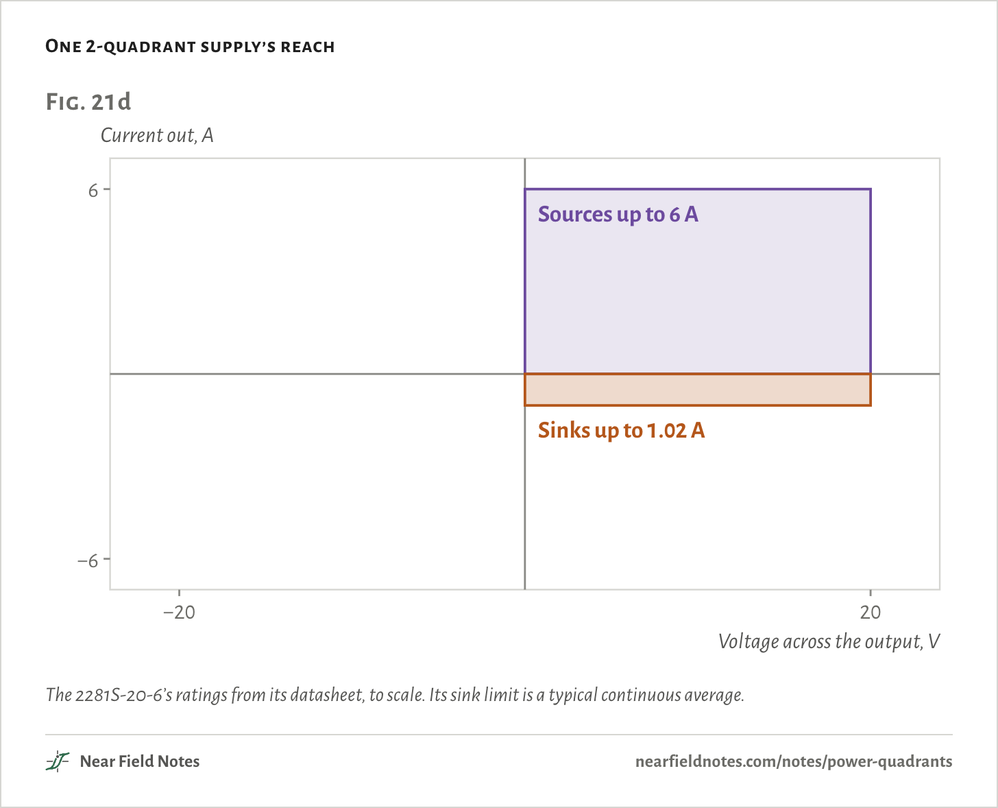
Sink ratings often run small. Keithley’s 2281S-20-6 battery simulator sources 6 A but sinks about 1 A. In Fig. 21c, a 1 A sink only slows the climb, to a peak of 50.7 V.
One 2-quadrant supply’s reach
The 2281S-20-6’s ratings from its datasheet, to scale. Its sink limit is a typical continuous average.The numbers
2281S-20-6
Datasheet
Voltage
0 to 20 V
Sources
Up to 6 A, 120 W
Sinks
Up to 1.02 A, typical, continuous average
4 quadrants: anywhere on the plane
A linear stage on ±25 V rails
Return the pull-down to a negative rail, and the output can swing below zero too. With its transistors on ±25 V rails, this stage reaches ±20 V and ±5 A, in all four quadrants.
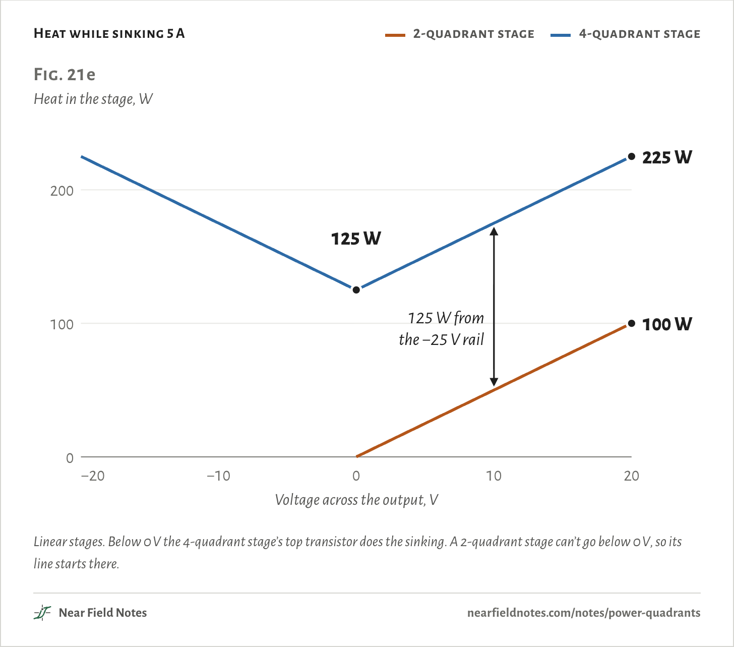
The negative rail costs heat. Sinking at positive voltage, the pull-down now has the output voltage plus the rail’s 25 V across it:
P4=Is(V+Vr)
=5 A×(20 V + 25 V)=225 W
That’s the same 5 A taken in at 20 V. The circuit gives the stage 100 W, and the stage burns 225 W.
Heat while sinking 5 A
2-quadrant stage
4-quadrant stage
Linear stages. Below 0 V the 4-quadrant stage’s top transistor does the sinking. A 2-quadrant stage can’t go below 0 V, so its line starts there.The numbers
Sinking 5 A. Linear stages. Rails at ±25 V for 4 quadrants, +25 V and ground for 2.
Output
4-quadrant stage
2-quadrant stage
Taken from the circuit
−20 V
225 W
can’t go there
100 W
−15 V
200 W
can’t go there
75 W
−10 V
175 W
can’t go there
50 W
−5 V
150 W
can’t go there
25 W
0 V
125 W
0 W
0 W
5 V
150 W
25 W
25 W
10 V
175 W
50 W
50 W
15 V
200 W
75 W
75 W
20 V
225 W
100 W
100 W
412
Linear 4-quadrant stage
225 W to take 100 W
Field marks. Sinking 5 A at +20 V, the pull-down transistor has 45 V across it. It burns 225 W, 100 W from your circuit and 125 W from its own negative rail.
Look-alike. A sink burns what it takes. That holds for the 2-quadrant stage, 100 W here. The 4-quadrant stage burns 125 W more at every voltage, because its pull-down returns to −25 V, not ground.
Range. At 0 V, sinking 5 A still burns 125 W. Sourcing costs far less: 5 A out at +20 V burns 25 W. At −20 V the two transistors swap roles.
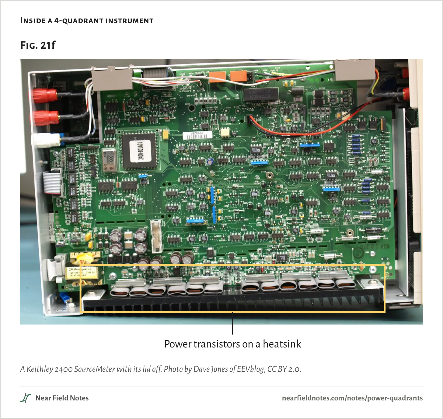
Habitat. Linear SMUs and bipolar supplies, where the output transistors sit on a heatsink. Fig. 21f shows one inside.
413
Why each step costs more
The rest of the bill
Each quadrant adds hardware. A 2-quadrant supply needs a second output transistor and its drive. What it sinks has to go into a big enough heatsink or through a switching stage back to the grid. Its current has to pass cleanly from one transistor to the other each time it crosses 0 A.
A 4-quadrant supply adds the negative rail. Its control has to stay stable while the load pushes back. It also watches four limits, ±V and ±I, instead of two.
Inside a 4-quadrant instrument
A Keithley 2400 SourceMeter with its lid off. Photo by Dave Jones of EEVblog, CC BY 2.0.
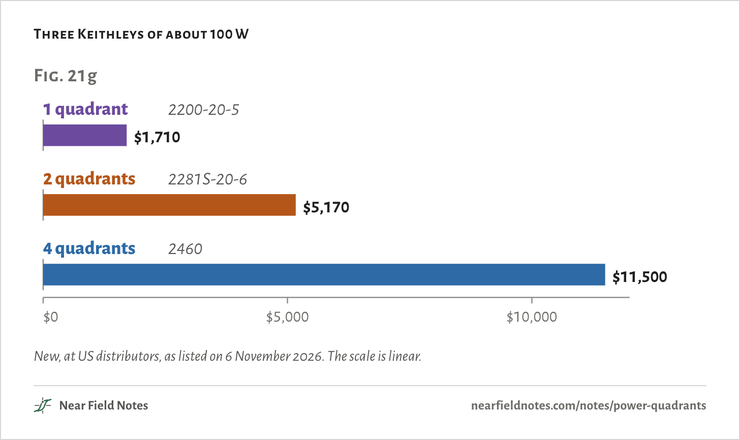
The prices follow. Three Keithley instruments of about 100 W list at $1,710, $5,170 and $11,500. The 2-quadrant one costs 3.0 times the bench supply, the 4-quadrant one 6.7 times.
Not all of that is quadrants. The 2460 is an SMU, a source-measure unit. That is a 4-quadrant supply with a precision meter built in. The meter is part of its price.
Three Keithleys of about 100 W
New, at US distributors, as listed on 6 November 2026. The scale is linear.The numbers
New, US distributors, listed on 6 November 2026.
Quadrants
Keithley
Rated
Price
Of the 1-quadrant
Listed by
1 quadrant
2200-20-5
20 V, 5 A, 100 W
$1,710
1.0×
Transcat
2 quadrants
2281S-20-6
20 V, 6 A, 120 W, sinks 1.02 A
$5,170
3.0×
Transcat
4 quadrants
2460
±100 V, ±7 A, 100 W
$11,500
6.7×
Valuetronics
Which one you need
One solar cell, three supplies
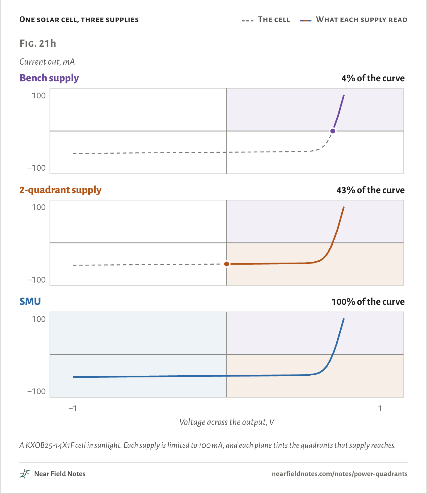
It depends on where your load goes on the plane. A solar cell under a full sweep visits three quadrants. Below 0 V it takes power. Between 0 and 0.69 V it makes power, and above 0.69 V it takes power again.
Sweep one from −1 V to +1 V, and each supply sees only the part it can reach.
One solar cell, three supplies
The cell
What each supply read
A KXOB25-14X1F cell in sunlight. Each supply is limited to 100 mA, and each plane tints the quadrants that supply reaches.The numbers
Cell: ANYSOLAR KXOB25-14X1F, 0.69 V open circuit, 58.6 mA short circuit. Every supply limited to 100 mA, reached at 0.763 V.
Supply
Reaches
Traces
Elsewhere
Bench supply
1 quadrant
4%
Floats to 0.69 V and reads 0 mA whenever the cell pushes current out
2-quadrant supply
2 quadrants
43%
Stays at 0 V and reads −58.6 mA for every setting below 0 V
SMU
4 quadrants
100%
Follows the whole curve
414
Solar cell sweep
4%, 43% and 100% of the curve
Field marks. The bench supply can’t take the cell’s current. Its output floats to 0.69 V and reads 0 mA for 85% of the sweep. The 2-quadrant supply stops at 0 V and reads −58.6 mA for every setting below it.
Look-alike. A dead cell. The bench supply reads 0 mA, as it would with nothing connected. The cell is fine. It holds the output at 0.69 V, above the setting, and the supply can’t take its current.
Range. The part most tests want, where the cell makes power, lies in quadrant 4. A 2-quadrant supply traces all of it, maximum power included.
Habitat. Solar cell tests. Reverse bias, below 0 V, takes a 4-quadrant supply.
415
Choosing a supply
Two questions
Two questions sort it. Does the load ever give power back? Does its voltage cross zero?
Key to supplies
Which supply does your load need?
1aThe load only ever takes powerGo to 2
1bIt sometimes gives power backGo to 3
2aIts voltage keeps one polarity1 quadrant
2bIts voltage crosses zero4 quadrants
3aIts voltage keeps one polarity2 quadrants
3bIts voltage crosses zero4 quadrants
A supply with floating outputs, wired the other way round, covers a negative voltage with the same quadrants. At 3a, check the sink rating against the current the load gives back. If it falls short, an electronic load across the output, in constant-voltage mode just above the supply’s setting, takes the rest.
Trace a load yourself
Seven loads
Pick a load and see the path it asks a supply to follow. Each part of the path is colored by the fewest quadrants that reach it.
Load
The path it asks for
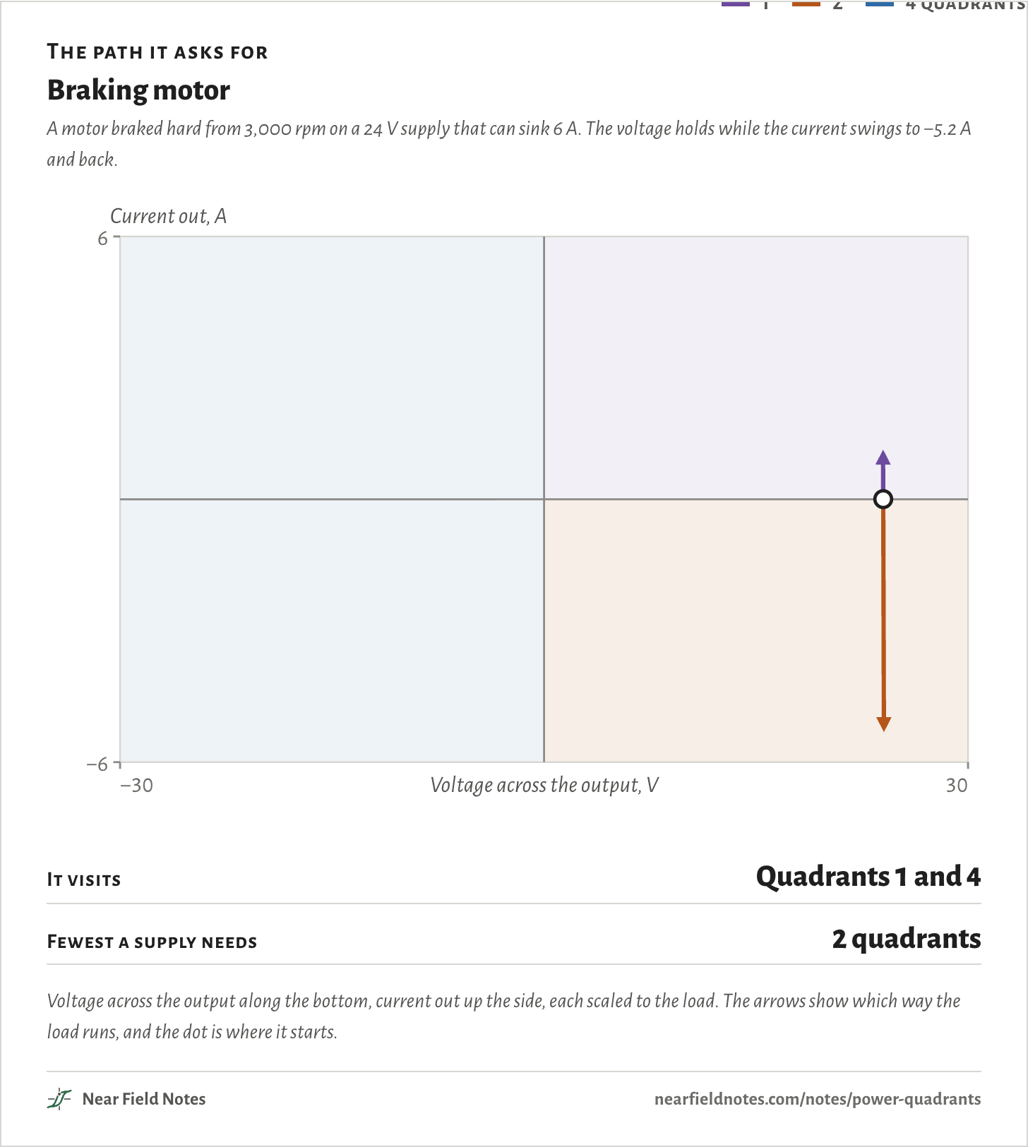
Braking motor
A motor braked hard from 3,000 rpm on a 24 V supply that can sink 6 A. The voltage holds while the current swings to −5.2 A and back.
1
2
4 quadrants
It visits
Quadrants 1 and 4
Fewest a supply needs
2 quadrants
Voltage across the output along the bottom, current out up the side, each scaled to the load. The arrows show which way the load runs, and the dot is where it starts.The numbers
Load
What it is
Quadrants it visits
Fewest a supply needs
Resistor
A 4 Ω resistor as the supply turns up from 0 to 20 V
1
1 quadrant
Charging a cell
One lithium-ion cell charged at constant current, 1 A up to 4.2 V, then at constant voltage until its current falls to 50 mA
1
1 quadrant
Acting as a cell
The supply acts as the cell, taking the same constant-current, constant-voltage charge from a charger under test
4
2 quadrants
Braking motor
A motor braked hard from 3,000 rpm on a 24 V supply that can sink 6 A. The voltage holds while the current swings to −5.2 A and back.
1 and 4
2 quadrants
Capacitor
4,700 µF on the output as the supply turns it down from 20 V to 0 V, taking 1 A
4
2 quadrants
Solar cell
One small solar cell in sunlight swept from −1 V to +1 V, with a 100 mA limit
1, 3 and 4
4 quadrants
Coil on AC
A 10 mH coil with 1 Ω of winding, driven with 5 A of 60 Hz current
1, 2, 3 and 4
4 quadrants
Conditions
Plane
Voltage across the supply’s output along the bottom, current out of its + terminal up the side. Quadrants counted counterclockwise from the top right, as in Keithley’s 2460 datasheet.
Coil
10 mH in series with 1 Ω, carrying 5 A peak at 60 Hz. Its voltage peaks at 19.5 V.
Output stages
Linear push-pull on ±25 V rails, ±20 V and ±5 A out. Each transistor drops what the rail and the output don’t share, with no bias current. The 2-quadrant stage returns its pull-down to ground.
Braking motor
qsim/regen.py’s model of moteus-c1’s bus: twelve 4.7 µF capacitors and an SMBJ48D TVS diode. The diode starts to conduct at 56 V, mid-range of its 54.1–58.1 V breakdown, and reaches 76.3 V at 7.9 A. An mj5208 motor, 330 rpm/V, braked at 20 A from 3,000 rpm. Its rotor’s inertia, its winding resistance and the running losses are assumed. Each supply has 1,000 µF and 10 mΩ at its output, and sinks at most 0, 1 or 6 A.
Solar cell
A single-diode model of the KXOB25-14X1F, fitted to its listed 0.69 V open circuit, 58.6 mA short circuit and 55 mA at 0.56 V. Its ideality factor, 1.2, and its shunt resistance, 300 Ω, are assumed.
Loads
The explorer’s paths come from the same models. The charge is an ideal constant-current, constant-voltage one: 1 A from 3.0 to 4.2 V, then 4.2 V until the current falls to 50 mA.
Prices
New, from US distributors’ listings on 6 November 2026.
Solver
Python. The motor’s bus is stepped every 0.2 µs. Everything else is in closed form or read off the models’ curves.
Models only. Nothing on this page has been measured.
Limits
Real supplies use more complex output stages, often behind a switching pre-regulator. The heat in Fig. 21e is for a plain linear stage.
The three supplies in Fig. 21c differ only in what they sink. Real ones also differ in speed and in output capacitance, which sets how fast the voltage climbs.
The 2281S-20-6’s 1.02 A is a typical continuous average from its datasheet.
Prices change, and part of an SMU’s price is its meter.
Files
qsim/site.pyEvery number on this page
qsim/regen.pyThe braking motor and moteus-c1’s bus
qsim/solar.pyThe solar cell and the three supplies that sweep it