Near Field Notes

Note 28Signal integrityRev 1Watch the video · 3:14

CRCs on fast links

How does a CRC catch bad bits, and what do fast links do when it fails?

It divides the frame by a fixed polynomial and sends the remainder, and the receiver’s own division has to land on a known constant. Ethernet’s CRC-32 catches any 3 flipped bits in a full 1518-byte frame, and any burst up to 32 bits long. Ethernet drops a bad frame, PCIe and DDR memory send it again, and a cut-through switch that has already sent most of it stomps its CRC so the next box knows.

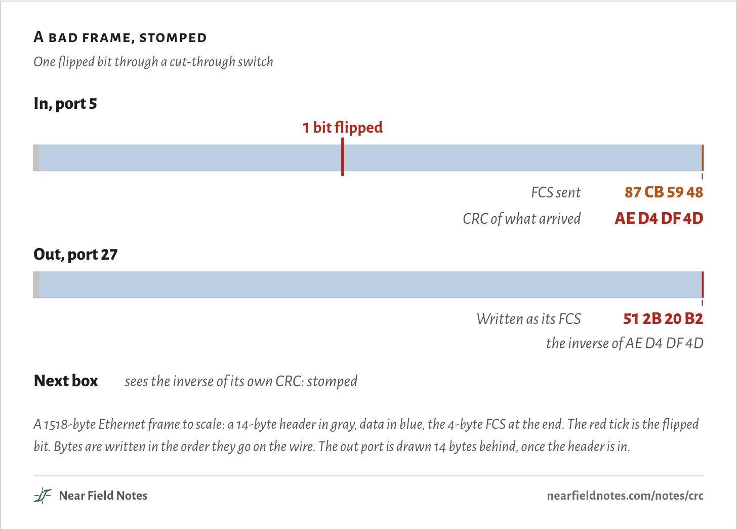
In the figure one bit flips at byte 700 on the way into a switch. The switch is sending the frame on before it has all arrived, so when the check fails at the end it marks the frame dead instead.

A bad frame, stomped

One flipped bit through a cut-through switch

In, port 51 bit flipped87 CB 59 48FCS sentAE D4 DF 4DCRC of what arrivedOut, port 2751 2B 20 B2Written as its FCSthe inverse of AE D4 DF 4DNext boxsees the inverse of its own CRC: stompedIn, port 51 bit flipped87 CB 59 48FCS sentAE D4 DF 4DCRC of what arrivedOut, port 2751 2B 20 B2Written as its FCSthe inverse of AE D4 DF 4DNext boxsees the inverse of its own CRC: stompedIn, port 51 bit flipped87 CB 59 48FCS sentAE D4 DF 4DCRC of what arrivedOut, port 2751 2B 20 B2Written as its FCSthe inverse of AE D4 DF 4DNext boxsees the inverse of its own CRC: stomped
A 1518-byte Ethernet frame to scale: a 14-byte header in gray, data in blue, the 4-byte FCS at the end. The red tick is the flipped bit. Bytes are written in the order they go on the wire. The out port is drawn 14 bytes behind, once the header is in.
The numbers
Bytes in the order they go on the wire.
Value
Frame1518 bytes: 14 of header, 1500 of data, 4 of FCS
Flipped on the way inByte 700, bit 3
FCS sent87 CB 59 48
CRC of what arrivedAE D4 DF 4D
FCS written out51 2B 20 B2, the inverse of AE D4 DF 4D
The next boxIts CRC of the frame is the inverse of the FCS: stomped

The frame check sequence

Four bytes on every Ethernet frame

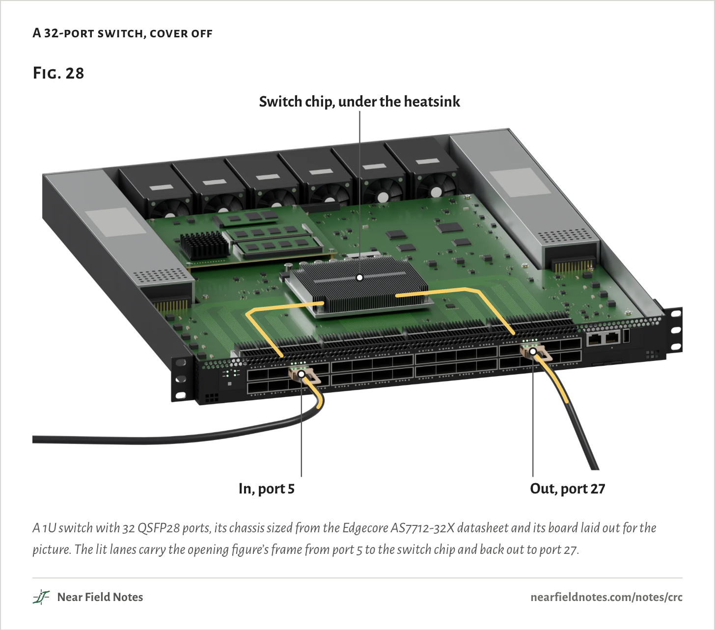
A switch like this one takes frames in on one port and sends them out another. The chip under the big heatsink reads each frame’s header to pick the port, and checks its last four bytes on the way through.

At 100 Gb/s a port carries more than 8 million full frames a second. Every one ends in the same kind of check, and every port of every box along the path runs it again.

A 32-port switch, cover off
Fig. 28Switch chip, under the heatsinkIn, port 5Out, port 27Fig. 28Switch chip, under the heatsinkIn, port 5Out, port 27Fig. 28Switch chip, under the heatsinkIn, port 5Out, port 27
A 1U switch with 32 QSFP28 ports, its chassis sized from the Edgecore AS7712-32X datasheet and its board laid out for the picture. The lit lanes carry the opening figure’s frame from port 5 to the switch chip and back out to port 27.
The numbers
PartValue
Ports32 QSFP28, 100 Gb/s each
InPort 5
OutPort 27
Size438.4 × 515.0 × 43.5 mm, the Edgecore AS7712-32X’s
BoardSchematic: placed for the picture

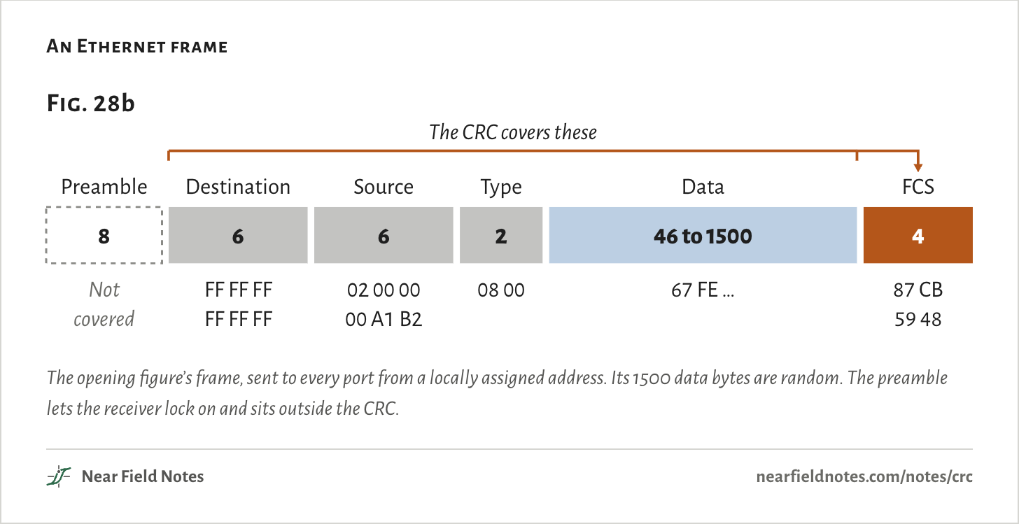
Those four bytes are the frame check sequence, the FCS. The sender runs a CRC over everything from the destination address to the last data byte and puts the result at the end.

The receiver runs the same CRC over the same bytes. If its answer doesn’t match, at least one bit changed on the way.

An Ethernet frame
Fig. 28bPreamble8 bytesNot coveredDestination6 bytesFF FF FF FF FF FFSource6 bytes02 00 00 00 A1 B2Type2 bytes08 00Data46 to 1500 bytes67 FE …The CRC covers the bracketed fieldsFCS4 bytes87 CB 59 48Fig. 28bPreamble8 bytesNot coveredDestination6 bytesFF FF FF FF FF FFSource6 bytes02 00 00 00 A1 B2Type2 bytes08 00Data46 to 1500 bytes67 FE …The CRC covers the bracketed fieldsFCS4 bytes87 CB 59 48Fig. 28b8PreambleNotcovered6DestinationFF FF FFFF FF FF6Source02 00 0000 A1 B22Type08 0046 to 1500Data67 FE …4FCS87 CB59 48The CRC covers these
The opening figure’s frame, sent to every port from a locally assigned address. Its 1500 data bytes are random. The preamble lets the receiver lock on and sits outside the CRC.
The numbers
The opening figure’s frame, bytes in wire order.
FieldBytesThis frameCovered by the CRC
Preamble and start delimiter8—No
Destination6FF FF FF FF FF FFYes
Source602 00 00 00 A1 B2Yes
Type208 00Yes
Data46 to 150067 FE …Yes
FCS487 CB 59 48Is the CRC

Division with XOR

A 4-bit CRC by hand

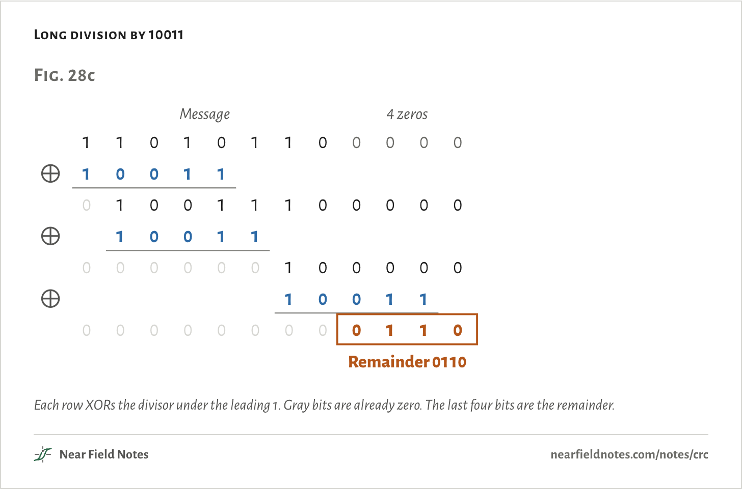
A CRC treats the message as one long binary number and divides it by a fixed divisor, the generator polynomial. The CRC is the remainder.

This page writes a polynomial as its coefficient bits, highest power first, so 10011 is x4 + x + 1. Subtraction is XOR, with no borrows. The sender adds as many zeros as the CRC has bits and divides:

R(x)=M(x)·xnmodG(x)

=110101100000mod10011=0110

The sender sends 11010110 0110, the message with its remainder. Divide that by 10011 and the remainder is 0000, so a receiver can check by dividing everything it got.

Long division by 10011
Fig. 28cMessage4 zeros110101100000100110100111000001001100000010000010011000000000110Remainder 0110Fig. 28cMessage4 zeros110101100000100110100111000001001100000010000010011000000000110Remainder 0110Fig. 28cMessage4 zeros110101100000100110100111000001001100000010000010011000000000110Remainder 0110
Each row XORs the divisor under the leading 1. Gray bits are already zero. The last four bits are the remainder.
The numbers
Coefficient bits, highest power first.
StepBits
Message and 4 zeros110101100000
XOR 10011 at bit 0010011100000
XOR 10011 at bit 1000000100000
XOR 10011 at bit 6000000000110
Remainder0110

The register that divides

One bit a clock

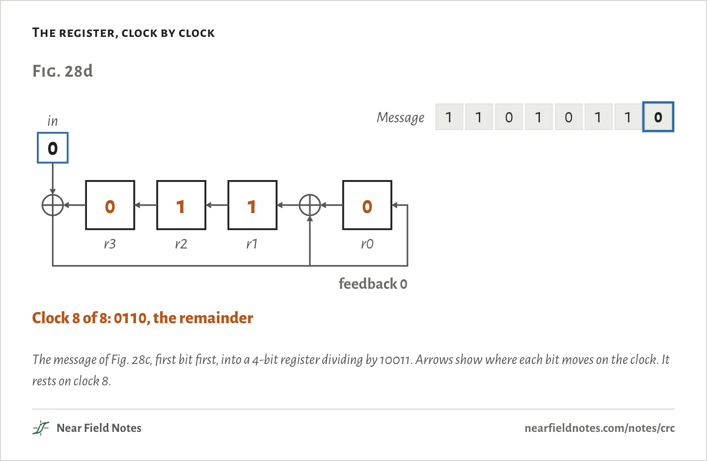
Hardware does the same division with a shift register and two XOR gates. Each clock one message bit goes in.

The bit falling out of r3 is XORed with the bit coming in. If the result is 1, it XORs the divisor into the register as everything shifts left. That is one step of the long division.

After the eighth bit the register holds 0110, the same remainder as Fig. 28c, and this form of the register needs no zeros added.

The register, clock by clock
Fig. 28dMessager3r2r1r0in11010110feedback0000Start: the register holds 0000110101101feedback 10011Clock 1 of 8110101101feedback 10101Clock 2 of 8110101100feedback 01010Clock 3 of 8110101101feedback 00100Clock 4 of 8110101100feedback 01000Clock 5 of 8110101101feedback 00000Clock 6 of 8110101101feedback 10011Clock 7 of 8110101100feedback 00110Clock 8 of 8: 0110, the remainderFig. 28dMessager3r2r1r0in11010110feedback0000Start: the register holds 0000110101101feedback 10011Clock 1 of 8110101101feedback 10101Clock 2 of 8110101100feedback 01010Clock 3 of 8110101101feedback 00100Clock 4 of 8110101100feedback 01000Clock 5 of 8110101101feedback 00000Clock 6 of 8110101101feedback 10011Clock 7 of 8110101100feedback 00110Clock 8 of 8: 0110, the remainderFig. 28dMessager3r2r1r0in11010110feedback0000Start: the register holds 0000110101101feedback 10011Clock 1 of 8110101101feedback 10101Clock 2 of 8110101100feedback 01010Clock 3 of 8110101101feedback 00100Clock 4 of 8110101100feedback 01000Clock 5 of 8110101101feedback 00000Clock 6 of 8110101101feedback 10011Clock 7 of 8110101100feedback 00110Clock 8 of 8: 0110, the remainder
The message of Fig. 28c, first bit first, into a 4-bit register dividing by 10011. Arrows show where each bit moves on the clock. It rests on clock 8.
The numbers
ClockBit inFeedbackr3 r2 r1 r0
0——0000
1110011
2110101
3001010
4100100
5001000
6100000
7110011
8000110

Ethernet’s 32-bit register

04C11DB7

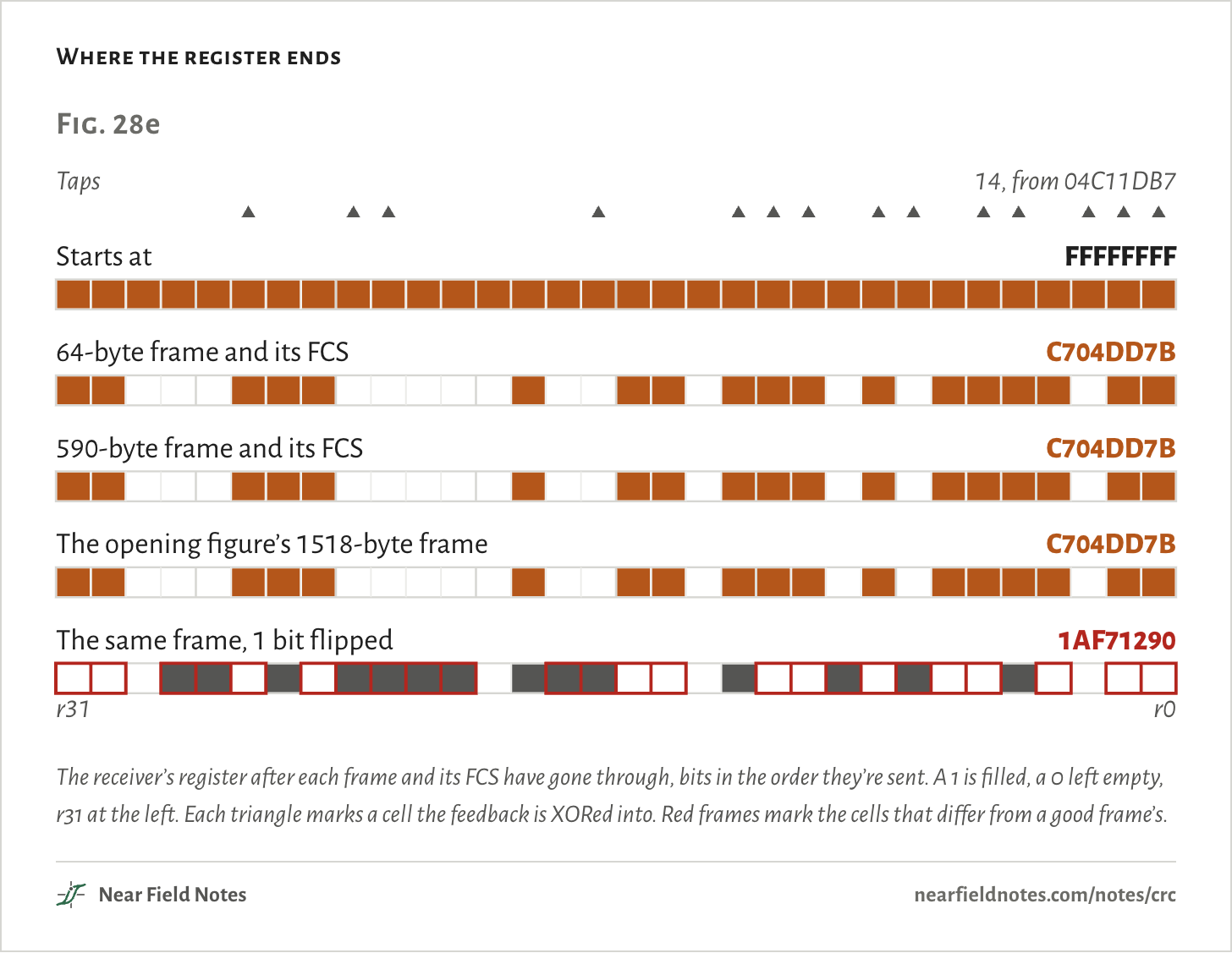
Ethernet’s divisor has 33 bits, from x32 down to 1. Written in hex with its top bit left off, as specs usually write it, it is 04C11DB7. Its register has 32 cells and 14 taps.

The register starts at all ones, and the sender flips the CRC’s bits before sending it. Because of those two choices, a receiver that runs the whole frame and its FCS through the register doesn’t land on zero.

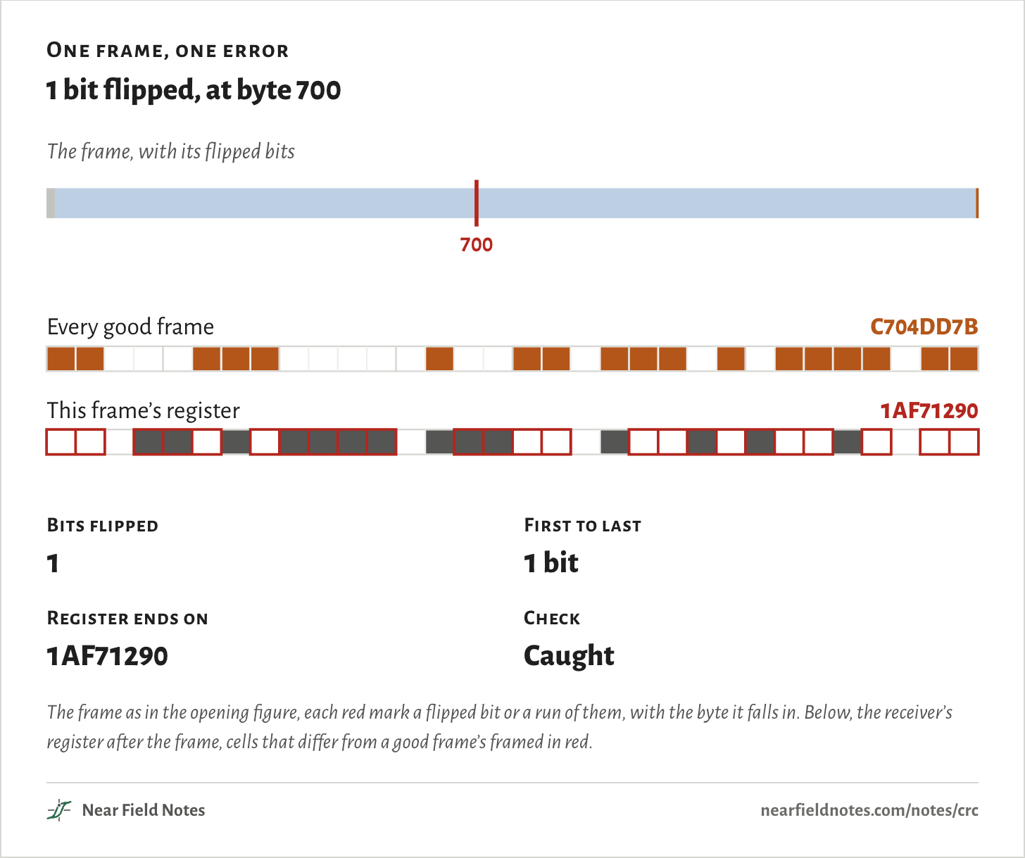
It lands on C704DD7B for every good frame of every length. One flipped bit in the 1518-byte frame and it ends on 1AF71290 instead.

Where the register ends
Fig. 28eTaps14, from 04C11DB7Starts atFFFFFFFF64-byte frame and its FCSC704DD7B590-byte frame and its FCSC704DD7BThe opening figure’s 1518-byte frameC704DD7BThe same frame, 1 bit flipped1AF71290r31r0Fig. 28eTaps14, from 04C11DB7Starts atFFFFFFFF64-byte frame and its FCSC704DD7B590-byte frame and its FCSC704DD7BThe opening figure’s 1518-byte frameC704DD7BThe same frame, 1 bit flipped1AF71290r31r0Fig. 28eTaps14, from 04C11DB7Starts atFFFFFFFF64-byte frame and its FCSC704DD7B590-byte frame and its FCSC704DD7BThe opening figure’s 1518-byte frameC704DD7BThe same frame, 1 bit flipped1AF71290r31r0
The receiver’s register after each frame and its FCS have gone through, bits in the order they’re sent. A 1 is filled, a 0 left empty, r31 at the left. Each triangle marks a cell the feedback is XORed into. Red frames mark the cells that differ from a good frame’s.
The numbers
Bits go in the order they're sent.
RunRegister at the endr31 … r0
Starts atFFFFFFFF11111111111111111111111111111111
64-byte frame and its FCSC704DD7B11000111000001001101110101111011
590-byte frame and its FCSC704DD7B11000111000001001101110101111011
The opening figure’s 1518-byte frameC704DD7B11000111000001001101110101111011
The same frame, 1 bit flipped1AF7129000011010111101110001001010010000

What it always catches

By frame length

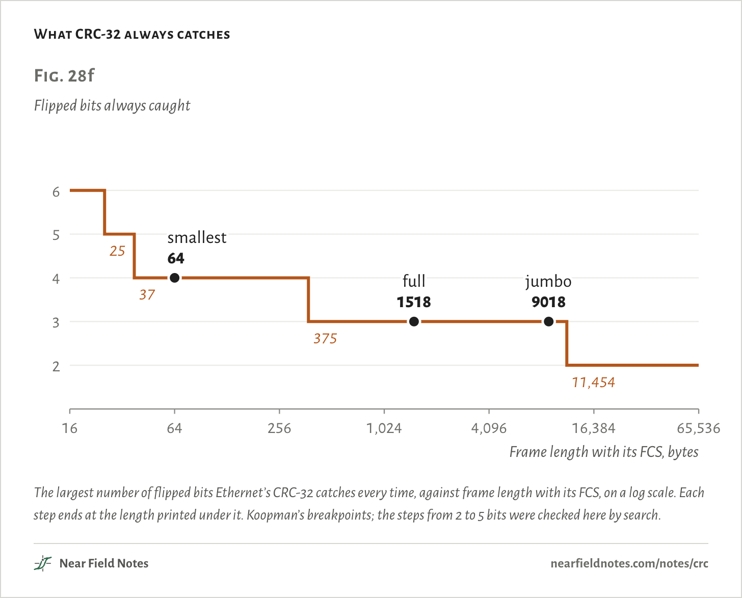
Any error is itself a pattern of flipped bits. The CRC misses it only if that pattern divides by the polynomial exactly, and a polynomial can be chosen so that no pattern of a few bits does.

For Ethernet’s, the guarantee depends on length. Any 4 flipped bits are caught in frames up to 375 bytes, and any 3 up to 11,454 bytes, which covers full frames and 9018-byte jumbo frames. Any burst up to 32 bits long is caught at every length.

Past the guarantee, a few patterns slip through. In a full frame they are a tiny share of all 4-bit errors:

P=W4N(N− 1)(N− 2)(N− 3) ÷ 24

=223,059905,776,814,103,876=1 in 4.06 billionfor N = 12,144

What CRC-32 always catches
Fig. 28fFlipped bits always caught23456162564,09665,536Frame length with its FCS, bytes64smallest1518full9018jumbo253737511,454Fig. 28fFlipped bits always caught2345616642561,0244,09616,38465,536Frame length with its FCS, bytes64smallest1518full9018jumbo253737511,454Fig. 28fFlipped bits always caught2345616642561,0244,09616,38465,536Frame length with its FCS, bytes64smallest1518full9018jumbo253737511,454
The largest number of flipped bits Ethernet’s CRC-32 catches every time, against frame length with its FCS, on a log scale. Each step ends at the length printed under it. Koopman’s breakpoints; the steps from 2 to 5 bits were checked here by search.
The numbers
Koopman’s breakpoints for 04C11DB7, from data bits to bytes with the 4-byte FCS.
Flipped bits always caughtFrame length with FCS, bytesEthernet frames in that range
6Up to 25None: the smallest is 64 bytes
526 to 37None
438 to 37564 bytes up to 375
3376 to 11,4541518-byte frames and 9018-byte jumbos
211,455 and longerNone

One polynomial, five CRC-32s

Hammond, Brown and Liu, 1975

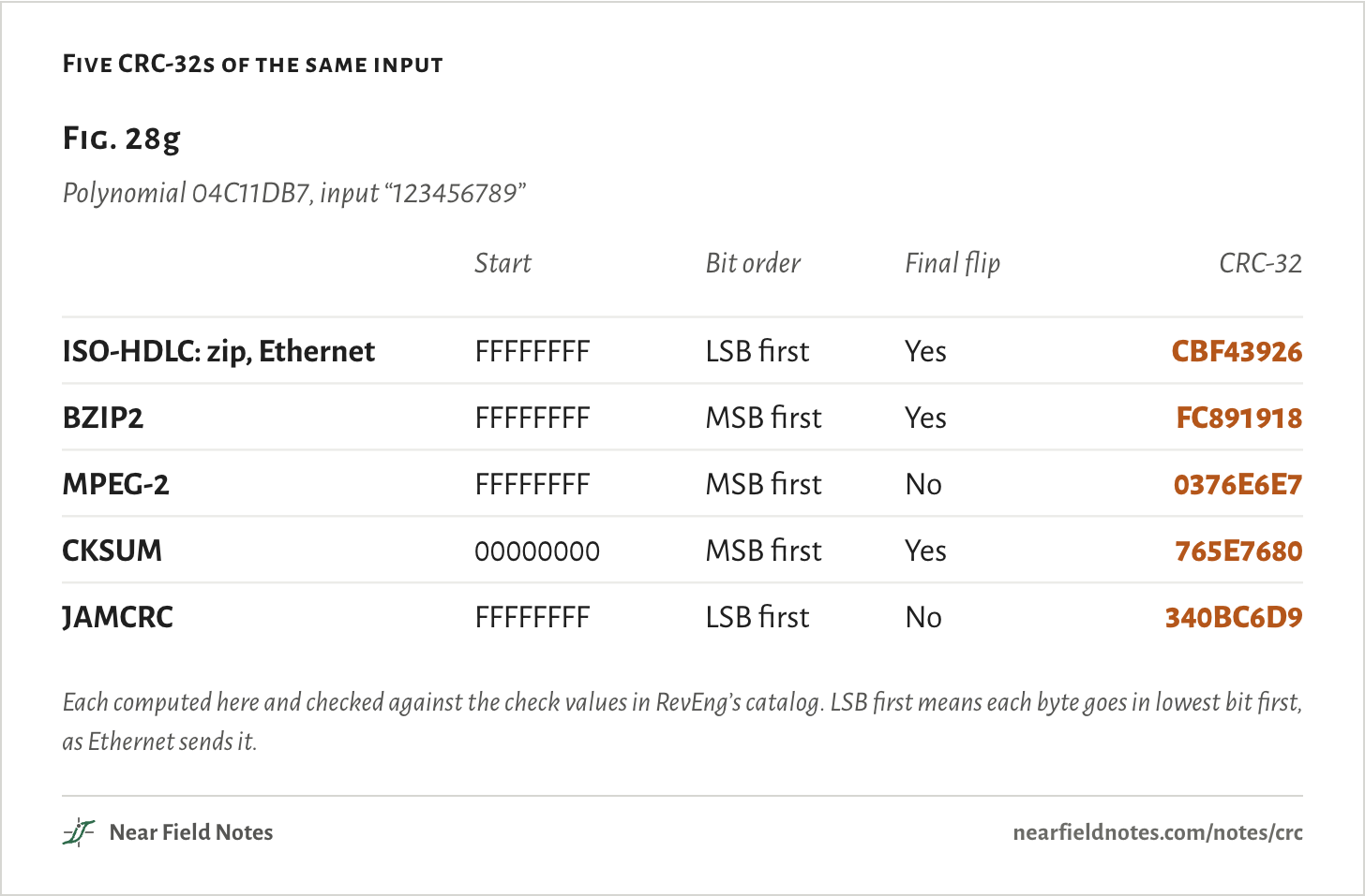
The polynomial alone doesn’t pin a CRC down. The start value, the bit order and the final flip all change the answer, and each mix has its own name. Two tools that both say CRC-32 can disagree on every file.

Five CRC-32s of the same input
Fig. 28gPolynomial 04C11DB7, input “123456789”ISO-HDLC: zip, EthernetCBF43926Start FFFFFFFF · LSB first · final flip yesBZIP2FC891918Start FFFFFFFF · MSB first · final flip yesMPEG-20376E6E7Start FFFFFFFF · MSB first · final flip noCKSUM765E7680Start 00000000 · MSB first · final flip yesJAMCRC340BC6D9Start FFFFFFFF · LSB first · final flip noFig. 28gPolynomial 04C11DB7, input “123456789”ISO-HDLC: zip, EthernetCBF43926Start FFFFFFFF · LSB first · final flip yesBZIP2FC891918Start FFFFFFFF · MSB first · final flip yesMPEG-20376E6E7Start FFFFFFFF · MSB first · final flip noCKSUM765E7680Start 00000000 · MSB first · final flip yesJAMCRC340BC6D9Start FFFFFFFF · LSB first · final flip noFig. 28gPolynomial 04C11DB7, input “123456789”StartBit orderFinal flipCRC-32ISO-HDLC: zip, EthernetFFFFFFFFLSB firstYesCBF43926BZIP2FFFFFFFFMSB firstYesFC891918MPEG-2FFFFFFFFMSB firstNo0376E6E7CKSUM00000000MSB firstYes765E7680JAMCRCFFFFFFFFLSB firstNo340BC6D9
Each computed here and checked against the check values in RevEng’s catalog. LSB first means each byte goes in lowest bit first, as Ethernet sends it.
The numbers
Name in RevEng’s catalogStartBit orderFinal flipCRC-32 of “123456789”
ISO-HDLC: zip, EthernetFFFFFFFFLSB firstYesCBF43926
BZIP2FFFFFFFFMSB firstYesFC891918
MPEG-2FFFFFFFFMSB firstNo0376E6E7
CKSUM00000000MSB firstYes765E7680
JAMCRCFFFFFFFFLSB firstNo340BC6D9
536

When the check fails

From each standard’s own documents

Every link below checks a CRC. They split on what happens next. Ethernet throws the frame away and leaves the resending to TCP. Short links that can’t lose data, like PCIe, SATA and memory, ask for it again on the spot. Every row links the spec, standards body or vendor it comes from. Note 14 shows where the check sits above each link’s PHY.

Ethernet, every speedCRC-32 FCS, 04C11DB7The frame, destination to data

The port drops it, and TCP sends again what isn’t acknowledged. A cut-through switch that has already sent most of it stomps its FCS.

AMD PG051, the FCSDIX Ethernet 1.0, 1980Cisco, CRC errorsCisco, stomped CRCsRFC 9293, TCP

PCIe 1.0 to 5.0 packetsLCRC, 32 bits, 04C11DB7The packet and its 12-bit sequence number

A NAK, and the sender replays from its retry buffer. After the 4th failed replay the link retrains.

PCIe Base 2.0PLX PEX 8604

PCIe link packetsCRC-16, 100BThe 6-byte DLLP

Discarded, and counted as a Bad DLLP error.

PCIe Base 2.0

PCIe end to endECRC, 32 bits, optionalHeader and data, end to end

The far end reports it and discards the packet. Switches pass the ECRC on unchanged.

PCIe Base 2.0PLX PEX 8604

PCIe 6.0 flits8 bytes, built on Reed-Solomon242 of the flit’s 256 bytes

Checked after the FEC. A NAK, and the flit is sent again.

PCI-SIG, PCIe 6.0Synopsys, FEC then CRC

USB 2.0CRC-5 tokens, CRC-16 dataA token’s fields, or the data

Ignored, with no handshake. The host tries up to 3 times.

USB 2.0 spec

USB 3.xCRC-16 header, 100B; CRC-32 data, 04C11DB7The 12-byte header; up to 1024 bytes of data

A bad header gets LBAD and is resent hop by hop. Bad data gets an ACK asking for a retry, end to end.

USB 3.2 spec

SATACRC-32, 04C11DB7, starting from 52325032Each frame, a FIS

R_ERR. A register FIS may be sent again. A data FIS should never be.

Serial ATA 1.0a

DDR4 and DDR5 memoryCRC-8, x⁸ + x² + x + 1, on DDR4 writes72 bits per byte lane per write

The DRAM pulses ALERT_n and the controller writes again. DDR5 checks reads too.

Micron DDR4Synopsys, DDR5

iSCSI and NVMe/TCPCRC-32C, 1EDC6F41, optionalEach PDU’s header and data, end to end

A bad header can’t be trusted for its length, so the receiver skips ahead or drops the connection. Bad data is rejected and recovered on iSCSI, and fails just that command on NVMe/TCP.

RFC 7143, iSCSINVMe/TCP 1.1

Errors inside the boxes

End to end

A link CRC covers one hop. Each switch checks the frame, holds it in memory, and computes a fresh FCS on the way out. A bit that flips inside the switch, after the check and before the new FCS, leaves with a valid CRC.

Stone and Partridge watched real traffic in 2000. Between 1 packet in 1,100 and 1 in 32,000 failed TCP’s checksum, on links whose CRCs should have missed about 1 error in 4 billion. The errors came from sources a link CRC can’t see, from memory errors to software bugs.

That is why PCIe has an optional end-to-end ECRC that switches pass on unchanged, and why iSCSI and NVMe over TCP put CRC-32C digests on their data.

Four levels, routine retries

PCIe 6.0, 2022

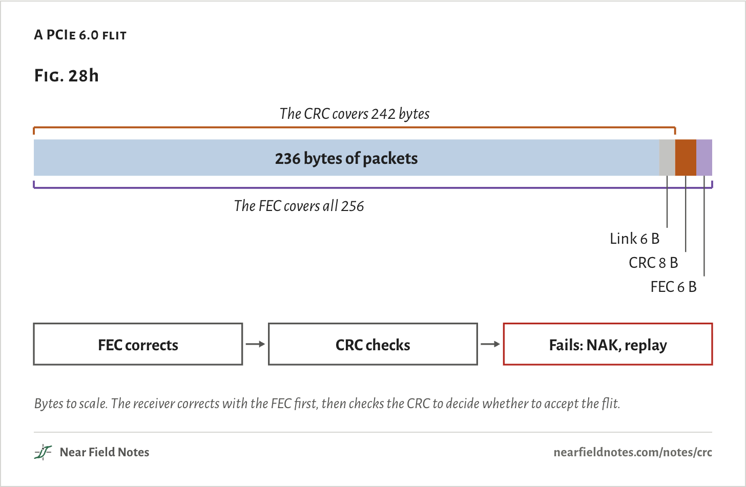
PCIe 6.0 runs four voltage levels at 64 GT/s. Its eyes shrink, and bit errors stop being rare. It sends fixed 256-byte flits with error correction built in, and one 8-byte CRC per flit replaces the CRC on each packet. Note 26 follows the flit from the line code side.

A PCIe 6.0 flit
Fig. 28h236 bytes of packetsThe CRC covers 242 bytesThe FEC covers all 256Link 6 BCRC 8 BFEC 6 BFEC correctsCRC checksFails: NAK, replayFig. 28h236 bytes of packetsThe CRC covers 242 bytesThe FEC covers all 256Link 6 BCRC 8 BFEC 6 BFEC correctsCRC checksFails: NAK, replayFig. 28h236 bytes of packetsThe CRC covers 242 bytesThe FEC covers all 256Link 6 BCRC 8 BFEC 6 BFEC correctsCRC checksFails: NAK, replay
Bytes to scale. The receiver corrects with the FEC first, then checks the CRC to decide whether to accept the flit.
The numbers
From PCI-SIG’s description of the PCIe 6.0 flit.
Part of the flitBytes
Packets236
Link6
CRC8
FEC6
538

At link speed

1024 bits a clock

One bit a clock would need a 400 GHz clock for 400G Ethernet. A MAC takes a wide word each clock instead:

f=Dw

=400 Gb/s1024 bits=391 MHz

Intel’s F-tile 400G MAC takes 1024 bits at 415 MHz or more when its error correction is on, a 2.41 ns clock.

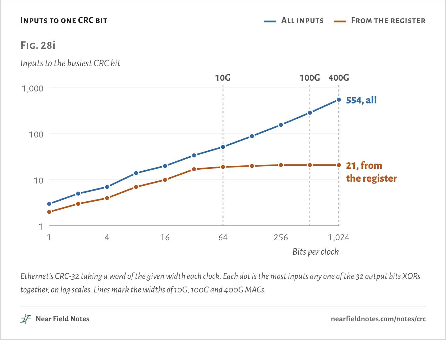
Write the register’s next state for a whole word at once and every output bit becomes one big XOR. At 8 bits a clock the busiest bit has 14 inputs. At 1024 it has 554, and only 21 of them come from the register itself.

A 64-byte frame takes 84 bytes of line with its preamble and the gap after it. The smallest frames arrive faster than the clock:

t=(64 + 20) bytes × 8D

=672 bits400 Gb/s=1.68 ns

So one word can hold the end of one frame and the end of the next, and the CRC logic has to finish both in one clock. AMD’s DCMAC is built for up to two frames a clock.

Inputs to one CRC bit
  • All inputs
  • From the register
Fig. 28iInputs to the busiest CRC bit1101001,00018641,024Bits per clock10G100G400G55421Fig. 28iInputs to the busiest CRC bit1101001,0001416642561,024Bits per clock10G100G400G554, all21, fromthe registerFig. 28iInputs to the busiest CRC bit1101001,0001416642561,024Bits per clock10G100G400G554, all21, fromthe register
Ethernet’s CRC-32 taking a word of the given width each clock. Each dot is the most inputs any one of the 32 output bits XORs together, on log scales. Lines mark the widths of 10G, 100G and 400G MACs.
The numbers
CRC-32, 04C11DB7, every output bit written out as one XOR.
Bits per clockInputs to the busiest bitFrom the registerFrom the dataTwo-input XORs, no sharing
132127
253254
4743108
81477220
16201010414
32341717872
645219341,390
1288920692,518
256157211384,424
512288212718,480
1,0245542153316,744

Which CRC, and what happens

From the link you have

The link sets the CRC, and the CRC’s place in the link sets what a failure does. The key sorts them.

Key to link CRCs

Which CRC does your link use, and what happens when it fails?

  1. 1aThe link carries Ethernet framesGo to 2
  2. 1bSomething elseGo to 3
  3. 2aStorage over TCP: iSCSI or NVMe/TCPFCS plus CRC-32C digests
  4. 2bAny other trafficCRC-32 FCS: dropped or stomped
  5. 3aDDR4 or DDR5 memoryWrite CRC: written again
  6. 3bPCIe, USB or SATAGo to 4
  7. 4aPCIeGo to 5
  8. 4bUSB or SATAGo to 6
  9. 5aIn flit mode, as at 64 GT/sFlit CRC after the FEC: replayed
  10. 5bNot in flit mode: PCIe 1.0 to 5.0LCRC each hop: replayed
  11. 6aSATACRC-32 from 52325032: R_ERR
  12. 6bUSBGo to 7
  13. 7aUSB 3, at 5 Gb/s and upCRC-16 and CRC-32: resent
  14. 7bUSB 2.0CRC-5 and CRC-16: up to 3 tries

At 2a, bad data is resent on iSCSI and fails its command on NVMe/TCP. At 2b, a stomped FCS is the inverse of the CRC the next box computes, so it counts the frame as damaged upstream. At 5b, the link retrains after the 4th failed replay, and PCIe’s link packets carry a CRC-16 of their own. At 6a, a register FIS may be sent again and a data FIS should never be. At 7a, a bad header is resent hop by hop and bad data is retried end to end.

Corrupt a frame yourself

Six errors, one frame

Pick an error. Each is flipped into the opening figure’s frame as sent, FCS and all, and the whole frame goes through the receiver’s register. A good frame ends on C704DD7B.

The two misses are real. The 4 bits at bytes 393, 610, 1121, 1124 are one of the 223,059 patterns the polynomial divides in a full frame, found by search. The 33-bit burst is the polynomial itself.

Error
One frame, one error

1 bit flipped, at byte 700

The frame, with its flipped bitsEvery good frameC704DD7B700This frame’s register1AF712901001400This frame’s register7850AF05307001500This frame’s register3F7C1A8E900–903This frame’s register285CE3033936101121–1124This frame’s registerC704DD7B1100–1104This frame’s registerC704DD7BThe frame, with its flipped bitsEvery good frameC704DD7B700This frame’s register1AF712901001400This frame’s register7850AF05307001500This frame’s register3F7C1A8E900–903This frame’s register285CE3033936101121–1124This frame’s registerC704DD7B1100–1104This frame’s registerC704DD7BThe frame, with its flipped bitsEvery good frameC704DD7B700This frame’s register1AF712901001400This frame’s register7850AF05307001500This frame’s register3F7C1A8E900–903This frame’s register285CE3033936101121–1124This frame’s registerC704DD7B1100–1104This frame’s registerC704DD7B
Bits flipped
1
First to last
1 bit
Register ends on
1AF71290
Check
Caught
The frame as in the opening figure, each red mark a flipped bit or a run of them, with the byte it falls in. Below, the receiver’s register after the frame, cells that differ from a good frame’s framed in red.
The numbers
Each error flipped into the opening figure’s 1518-byte frame as sent, FCS included, then run through the receiver’s register.
ErrorBits flippedFirst to last, bitsBytes hitRegister at the endCheck
1 bit flipped, at byte 700117001AF71290Caught
2 bits, 1,300 bytes apart210,406100, 14007850AF05Caught
3 bits across the frame311,75630, 700, 15003F7C1A8ECaught
A burst 32 bits long1032900, 901, 902, 903285CE303Caught
4 bits the polynomial misses45,855393, 610, 1121, 1124C704DD7BMissed
33 bits that match the polynomial15331100, 1101, 1102, 1103, 1104C704DD7BMissed

Conditions

Frame
1518 bytes: broadcast destination, source 02 00 00 00 A1 B2, type 08 00, 1500 bytes of seeded random data, then its FCS. One bit flipped at byte 700, bit 3.
CRC-32
Polynomial 04C11DB7 from FFFFFFFF, bytes in lowest bit first, final flip, checked against zlib. The receiver’s register is the shift-left form of Fig. 28d, run over the frame and its FCS in wire order.
Guarantees
Koopman’s breakpoints for 04C11DB7 and CRC-32C, and the count of 4-bit patterns each misses in a full frame, reproduced by search.
Errors
Flipped into the frame as sent. The 4-bit miss was found by searching for powers of x whose sum divides by the polynomial. The 32-bit burst has random bits between its two flipped ends.
Parallel CRC
The register’s next state written out for 1 to 1024 bits a clock, each output bit as one XOR, with no shared terms.
Render
Blender, one camera angle. The switch is generic.

Computed only. No frames were captured from a real link.

Limits

  • The switch is drawn, not modeled. Real cut-through switches wait for more than the header, and their delay varies.
  • The guarantees count flipped bits. Real links make bursts, and a descrambler below the CRC turns one line error into several flipped bits.
  • DDR5’s CRC width isn’t given here. The page gives DDR4’s from Micron and says only that DDR5 adds reads.
  • The parallel counts assume one XOR per output bit. Synthesis tools share terms and use far fewer gates.
  • SAS appears only as a user of the polynomial. Its handling of a failed CRC isn’t covered.

Files

  • sim/crc.pyThe frame, its FCS and its stomp, the CRC-4 division and register, the five CRC-32s and the 400G timing
  • sim/site.pyThe receiver’s register for good and bad frames, the explorer’s errors and the inputs per CRC bit
  • refs/checks/crc32_breakpoints.pyKoopman’s breakpoints and 4-bit counts for 04C11DB7 and CRC-32C
  • refs/checks/parallel_crc_matrix.pyThe parallel CRC equations at each word width
  • render/switch.pyThe switch with its cover off in Fig. 28

Sources

Like this note?

Rev 1 ·
  1. Rev 1First published

Each fix gets a line here, with the reader's name if they want credit.

Did it answer your question?

Want more on this?

Report a problem

What should the next note be? Ask for one