Near Field Notes

Note 24Signal integrityRev 1Watch the video · 2:27

I3C vs I2C

What is I3C, and how does it differ from I2C?

I3C is MIPI’s faster successor to I2C, on the same two wires. Its chips drive both lines up and down instead of waiting on pull-up resistors, so a 12-byte sensor read takes 13.1 µs and 28.2 nJ, against 344 µs and 203 nJ on I2C at 400 kHz. It also hands out addresses and carries interrupts over the bus, so the extra pins an I2C board needs go away.

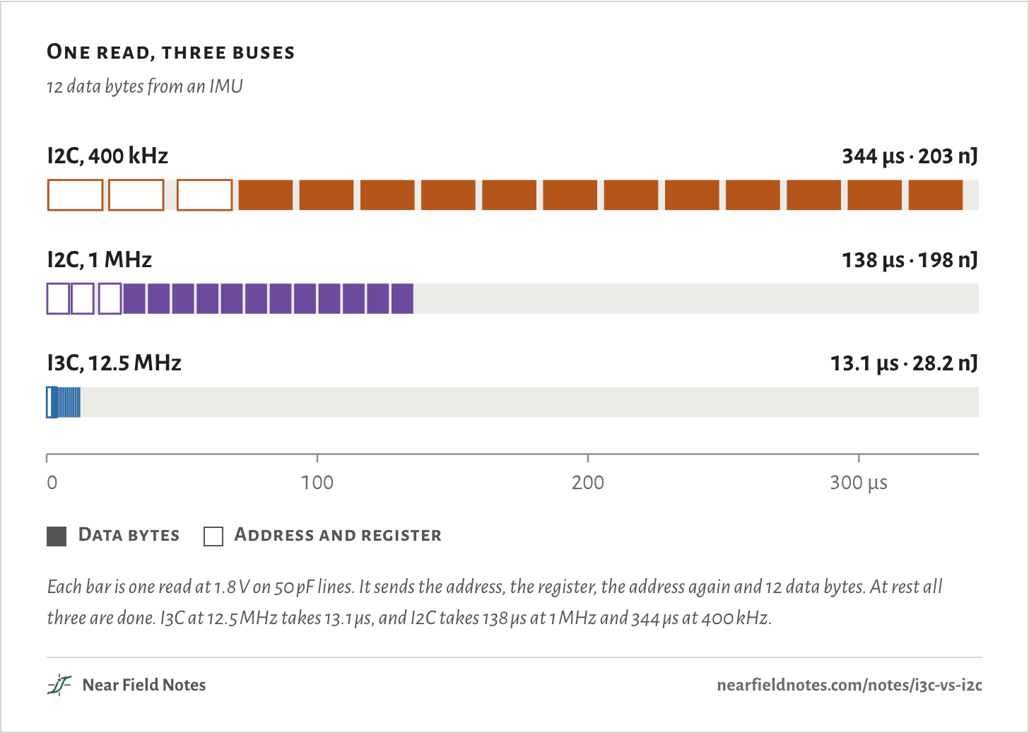
The figure runs one read on three buses at once, to one time scale. I3C is done before I2C at 400 kHz has sent its first byte.

One read, three buses

12 data bytes from an IMU

I2C, 400 kHz344 µs · 203 nJI2C, 1 MHz138 µs · 198 nJI3C, 12.5 MHz13.1 µs · 28.2 nJ0100200300 µsI2C, 400 kHz344 µs · 203 nJI2C, 1 MHz138 µs · 198 nJI3C, 12.5 MHz13.1 µs · 28.2 nJ0100200300 µsI2C, 400 kHz344 µs · 203 nJI2C, 1 MHz138 µs · 198 nJI3C, 12.5 MHz13.1 µs · 28.2 nJ0100200300 µs
  • Data bytes
  • Address and register
Each bar is one read at 1.8 V on 50 pF lines. It sends the address, the register, the address again and 12 data bytes. At rest all three are done. I3C at 12.5 MHz takes 13.1 µs, and I2C takes 138 µs at 1 MHz and 344 µs at 400 kHz.
The numbers
One read: START, the address, register 0x1F, a repeated START, the address again and 12 data bytes, then STOP and the bus-free time after it.
BusRead takesEnergyHow SCL goes high
I2C, 400 kHz344 µs203 nJ7.08 kΩ pull-up
I2C, 1 MHz138 µs198 nJ2.83 kΩ pull-up
I3C, 12.5 MHz13.1 µs28.2 nJdriven both ways

Seven sensors on one board

16 pins, or 2

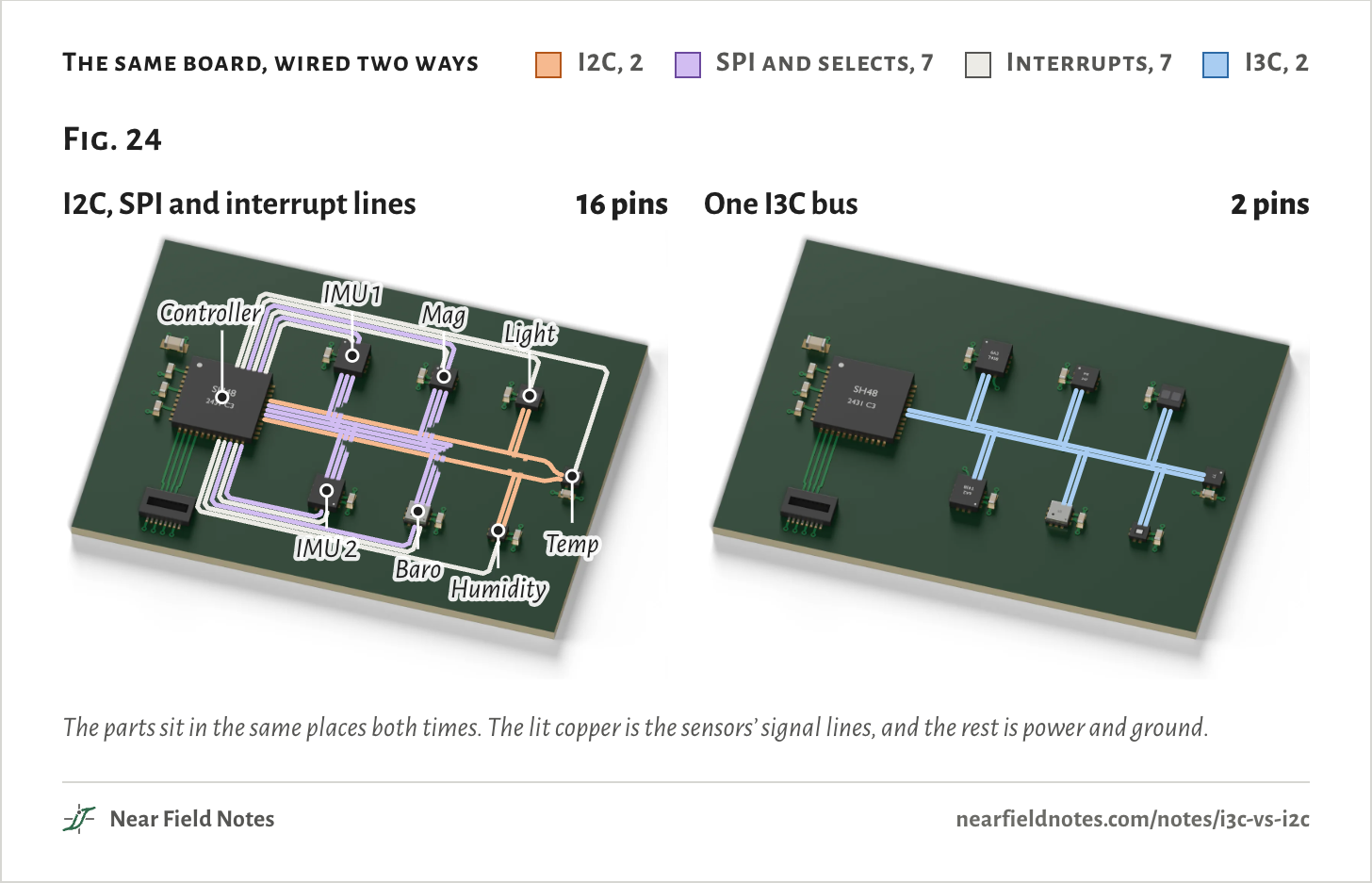
This board has a controller and seven sensors. Two are IMUs, and the others are a magnetometer, a barometer, and light, humidity and temperature sensors. Wired the usual way, the four fast ones share SPI and get a chip-select line each. The slow three share I2C.

Every sensor also has its own interrupt line, to say when it has new data. That takes 16 of the controller’s pins. On I3C all seven share two wires, and the interrupts come over them too.

The same board, wired two ways
  • I2C, 2
  • SPI and selects, 7
  • Interrupts, 7
  • I3C, 2
Fig. 24I2C, SPI and interrupt lines16 pinsControllerIMU 1MagLightIMU 2BaroHumidityTempOne I3C bus2 pinsFig. 24I2C, SPI and interrupt lines16 pinsControllerIMU 1MagLightIMU 2BaroHumidityTempOne I3C bus2 pinsFig. 24I2C, SPI and interrupt lines16 pinsControllerIMU 1MagLightIMU 2BaroHumidityTempOne I3C bus2 pins
The parts sit in the same places both times. The lit copper is the sensors’ signal lines, and the rest is power and ground.
The numbers
LinesPinsWired the usual wayOn I3C
I2C2SCL and SDA, to light, humidity and temperatureSCL and SDA, to all seven
SPI3SCLK, MOSI and MISO, to the IMUs, magnetometer and barometerNone
Chip selects4One for each SPI sensorNone
Interrupts7One for each sensorNone, they come over the bus
Total162

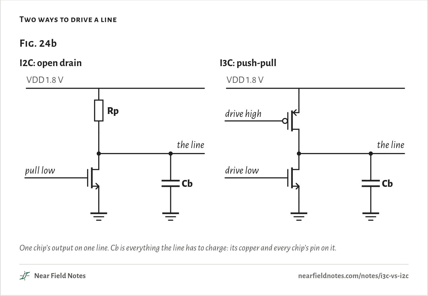
I2C, Philips’ bus from 1982, has two wires. SCL carries the clock and SDA the data. On both, a chip can only pull the line low. A resistor, the pull-up, brings it back up, so any chip can hold a line down and no two chips ever fight.

I3C keeps the two wires but drives them both ways. A chip pulls the line up as hard as it pulls it down. The pull-up stays only for the moments when two chips may talk at once.

Two ways to drive a line
Fig. 24bI2C: open drainVDD 1.8 VRppull lowCbthe lineI3C: push-pullVDD 1.8 Vdrive highdrive lowCbthe lineFig. 24bI2C: open drainVDD 1.8 VRppull lowCbthe lineI3C: push-pullVDD 1.8 Vdrive highdrive lowCbthe lineFig. 24bI2C: open drainI3C: push-pullVDD 1.8 VRppull lowCbthe lineVDD 1.8 Vdrive highdrive lowCbthe line
One chip’s output on one line. Cb is everything the line has to charge: its copper and every chip’s pin on it.

The pull-up sets the pace

One rise on 50 pF

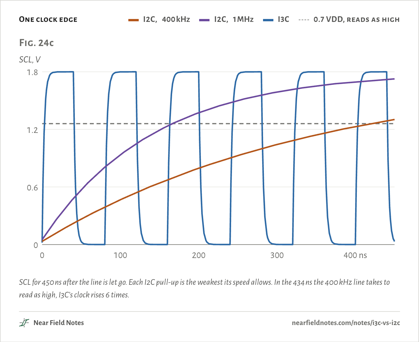
On I2C a line goes high only as fast as its pull-up can charge it. UM10204, NXP’s I2C spec, times that rise from 30% to 70% of the supply:

tr = 0.8473 Rp Cb

300 ns = 0.8473 × 7.08 kΩ × 50 pF

At 400 kHz the spec allows a 300 ns rise, so on a 50 pF line the pull-up can be at most 7.08 kΩ. Fast-mode Plus, at 1 MHz, allows 120 ns and 2.83 kΩ. A stronger pull-up rises faster, but it burns power whenever a chip holds the line low:

P = V2Rp

0.46 mW = (1.8 V)27.08 kΩ

That is 0.59 nJ in each 1.3 µs low half of a 400 kHz clock, against 0.16 nJ to charge the line back up.

One clock edge
  • I2C, 400 kHz
  • I2C, 1 MHz
  • I3C
  • 0.7 VDD, reads as high
Fig. 24cSCL, V00.61.21.80200400 nsFig. 24cSCL, V00.61.21.80100200300400 nsFig. 24cSCL, V00.61.21.80100200300400 ns
SCL for 450 ns after the line is let go. Each I2C pull-up is the weakest its speed allows. In the 434 ns the 400 kHz line takes to read as high, I3C’s clock rises 6 times.
The numbers
On 50 pF at 1.8 V.
BusPull-upRise, 30 to 70%
I2C, 400 kHz7.08 kΩ302 ns
I2C, 1 MHz2.83 kΩ122 ns
I3C, 12.5 MHznone, driven2.3 ns

Why MIPI made I3C

2013 to 2016

MIPI, the alliance whose camera links Note 14 looks at, lists I2C’s limits in its I3C FAQ. Its addresses are fixed at 7 bits, and an interrupt needs an extra wire. Its data rate is limited. Clock stretching lets one chip hang the bus. SPI needs three shared wires and a select line for every chip.

MIPI formed a Sensor Working Group in 2013. It wanted fewer pins, one standard way to talk to sensors, and one bus for the jobs of both I2C and SPI. In a 2022 talk, MIPI projected more than 20 sensors per device on average.

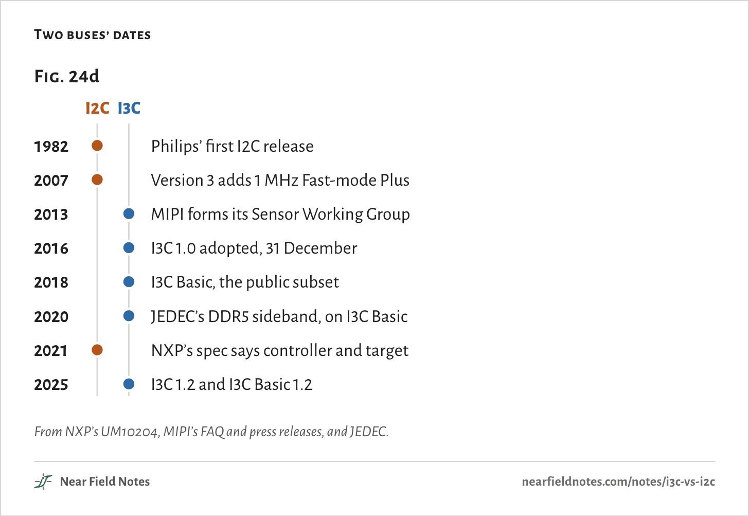
I3C stands for Improved Inter Integrated Circuit. Version 1.0 was adopted on 31 December 2016, and I3C Basic, a subset anyone can download, followed in 2018.

Two buses’ dates
Fig. 24dI2CI3C1982Philips’ first I2C release2007Version 3 adds 1 MHz Fast-mode Plus2013MIPI forms its Sensor Working Group2016I3C 1.0 adopted, 31 December2018I3C Basic, the public subset2020JEDEC’s DDR5 sideband, on I3C Basic2021NXP’s spec says controller and target2025I3C 1.2 and I3C Basic 1.2Fig. 24dI2CI3C1982Philips’ first I2C release2007Version 3 adds 1 MHz Fast-mode Plus2013MIPI forms its Sensor Working Group2016I3C 1.0 adopted, 31 December2018I3C Basic, the public subset2020JEDEC’s DDR5 sideband, on I3C Basic2021NXP’s spec says controller and target2025I3C 1.2 and I3C Basic 1.2Fig. 24dI2CI3C1982Philips’ first I2C release2007Version 3 adds 1 MHz Fast-mode Plus2013MIPI forms its Sensor Working Group2016I3C 1.0 adopted, 31 December2018I3C Basic, the public subset2020JEDEC’s DDR5 sideband, on I3C Basic2021NXP’s spec says controller and target2025I3C 1.2 and I3C Basic 1.2
From NXP’s UM10204, MIPI’s FAQ and press releases, and JEDEC.
The numbers
YearBusWhat happened
1982I2CPhilips’ first I2C release
2007I2CVersion 3 adds 1 MHz Fast-mode Plus
2013I3CMIPI forms its Sensor Working Group
2016I3CI3C 1.0 adopted, 31 December
2018I3CI3C Basic, the public subset
2020I3CJEDEC’s DDR5 sideband, on I3C Basic
2021I2CNXP’s spec says controller and target
2025I3CI3C 1.2 and I3C Basic 1.2

How I3C runs at 12.5 MHz

Driven both ways

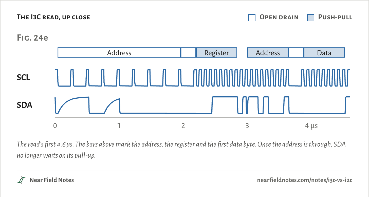
I3C’s plain mode, SDR, runs its clock at 12.5 MHz. Most of each read is driven both ways. Open drain comes back only where more than one chip may answer.

The I3C read, up close
  • Open drain
  • Push-pull
Fig. 24eAddressDataSCLSDA024 µsFig. 24eAddressDataSCLSDA01234 µsFig. 24eAddressRegisterAddressDataSCLSDA01234 µs
The read’s first 4.6 µs. The bars above mark the address, the register and the first data byte. Once the address is through, SDA no longer waits on its pull-up.
The numbers
Part of the readSDASCL lowSCL high
Address after STARTOpen drain200 ns40 ns
AcknowledgeOpen drain200 ns40 ns
Register, address after repeated START, dataPush-pull40 ns40 ns
464

Less energy per read

203 nJ, 198 nJ and 28.2 nJ

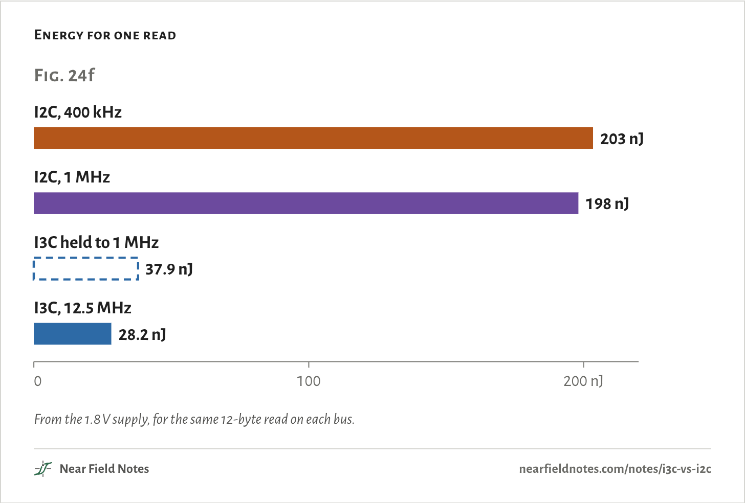
The same read draws 203 nJ from the 1.8 V supply on I2C at 400 kHz, and 28.2 nJ on I3C, 7.2 times less. On I3C most of it goes into charging the lines. A driven line takes this much from the supply each time it rises:

E = Cb V2

162 pJ = 50 pF × (1.8 V)2

SCL rises 137 times in the read, so the clock alone takes 22.2 nJ of the 28.2 nJ.

Energy for one read
Fig. 24fI2C, 400 kHz203 nJI2C, 1 MHz198 nJI3C held to 1 MHz37.9 nJI3C, 12.5 MHz28.2 nJ0100200 nJFig. 24fI2C, 400 kHz203 nJI2C, 1 MHz198 nJI3C held to 1 MHz37.9 nJI3C, 12.5 MHz28.2 nJ0100200 nJFig. 24fI2C, 400 kHz203 nJI2C, 1 MHz198 nJI3C held to 1 MHz37.9 nJI3C, 12.5 MHz28.2 nJ0100200 nJ
From the 1.8 V supply, for the same 12-byte read on each bus.
The numbers
With 30 random 12-byte payloads in place of the IMU’s: 182 nJ to 204 nJ at 400 kHz, 177 nJ to 198 nJ at 1 MHz, 29.1 nJ to 31.2 nJ on I3C.
BusEnergyTime
I2C, 400 kHz203 nJ344 µs
I2C, 1 MHz198 nJ138 µs
I3C held to 1 MHz37.9 nJ137 µs
I3C, 12.5 MHz28.2 nJ13.1 µs
466

Interrupts on the bus

The lower address wins

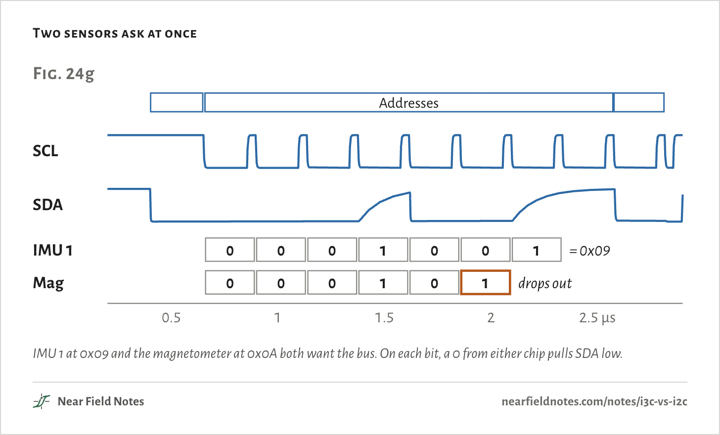
On I2C, a sensor with new data raises its own interrupt line. On I3C it asks on SDA instead, an in-band interrupt, and the address it then sends decides who goes first.

Two sensors ask at once
Fig. 24gAddressesSCLSDAIMU 10001001= 0x09Mag000101drops out12 µsFig. 24gAddressesSCLSDAIMU 10001001= 0x09Mag000101drops out0.511.522.5 µsFig. 24gAddressesSCLSDAIMU 10001001= 0x09Mag000101drops out0.511.522.5 µs
IMU 1 at 0x09 and the magnetometer at 0x0A both want the bus. On each bit, a 0 from either chip pulls SDA low.
The numbers
BitIMU 1, 0x09Mag, 0x0ASDA reads
1000
2000
3000
4111
5000
6010
71out1
468

Addresses handed out

48-bit IDs, lowest first

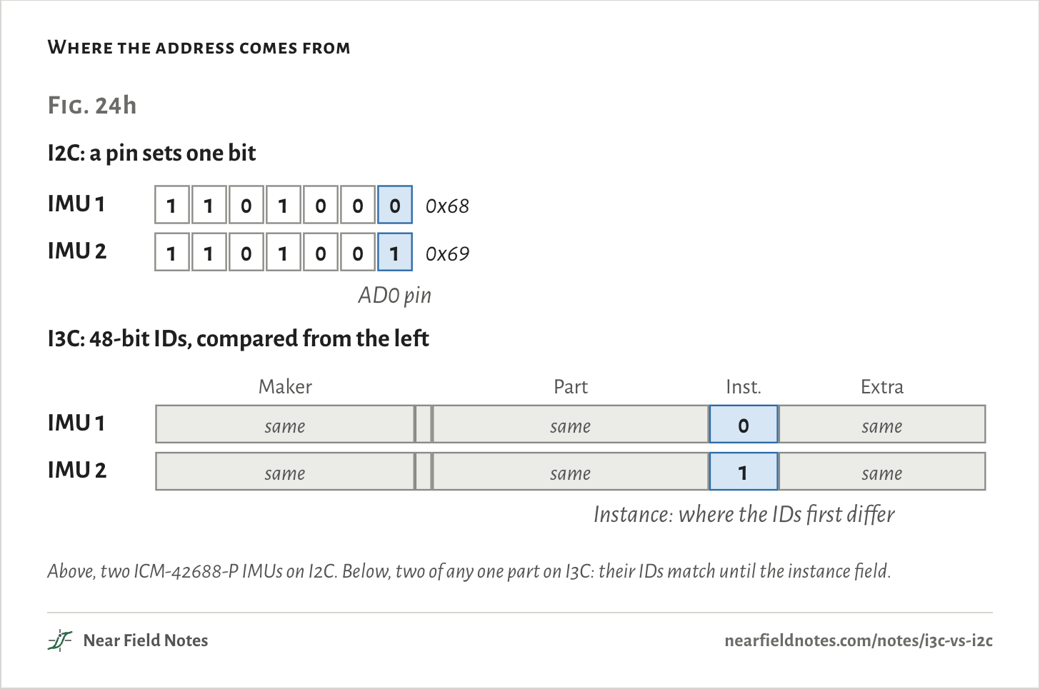
An I2C chip’s address is set when it is made, apart from a pin or two. An I3C controller gives each chip an address of its choosing when the bus starts up.

Where the address comes from
Fig. 24hI2C: a pin sets one bitIMU 111010000x68IMU 211010010x69AD0 pinI3C: 48-bit IDs, compared from the leftMakerPartExtraIMU 1samesame0sameIMU 2samesame1sameInstance: where the IDs first differFig. 24hI2C: a pin sets one bitIMU 111010000x68IMU 211010010x69AD0 pinI3C: 48-bit IDs, compared from the leftMakerPartExtraIMU 1samesame0sameIMU 2samesame1sameInstance: where the IDs first differFig. 24hI2C: a pin sets one bitIMU 111010000x68IMU 211010010x69AD0 pinI3C: 48-bit IDs, compared from the leftMakerPartInst.ExtraIMU 1samesame0sameIMU 2samesame1sameInstance: where the IDs first differ
Above, two ICM-42688-P IMUs on I2C. Below, two of any one part on I3C: their IDs match until the instance field.
The numbers
The 48-bit ID’s fields when the flag bit is 0, as Linux’s i3c/device.h reads them.
FieldBitsWidth
Maker47 to 3315
Random flag321
Part31 to 1616
Instance15 to 124
Extra11 to 012
470

Old I2C chips on the bus

Too quick to see

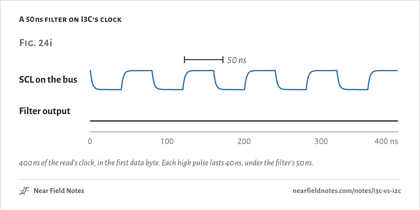
An I3C bus can keep I2C chips on it. They miss the I3C traffic because their own input filters throw it away.

A 50 ns filter on I3C’s clock
Fig. 24i50 nsSCL on the busFilter output0200400 nsFig. 24i50 nsSCL on the busFilter output0100200300400 nsFig. 24i50 nsSCL on the busFilter output0100200300400 ns
400 ns of the read’s clock, in the first data byte. Each high pulse lasts 40 ns, under the filter’s 50 ns.
The numbers
On the busAfter the filter
SCL rising edges in the read1371
SCL high, push-pull40 nsnot seen
472

Where I3C is used

Memory, servers, sensors

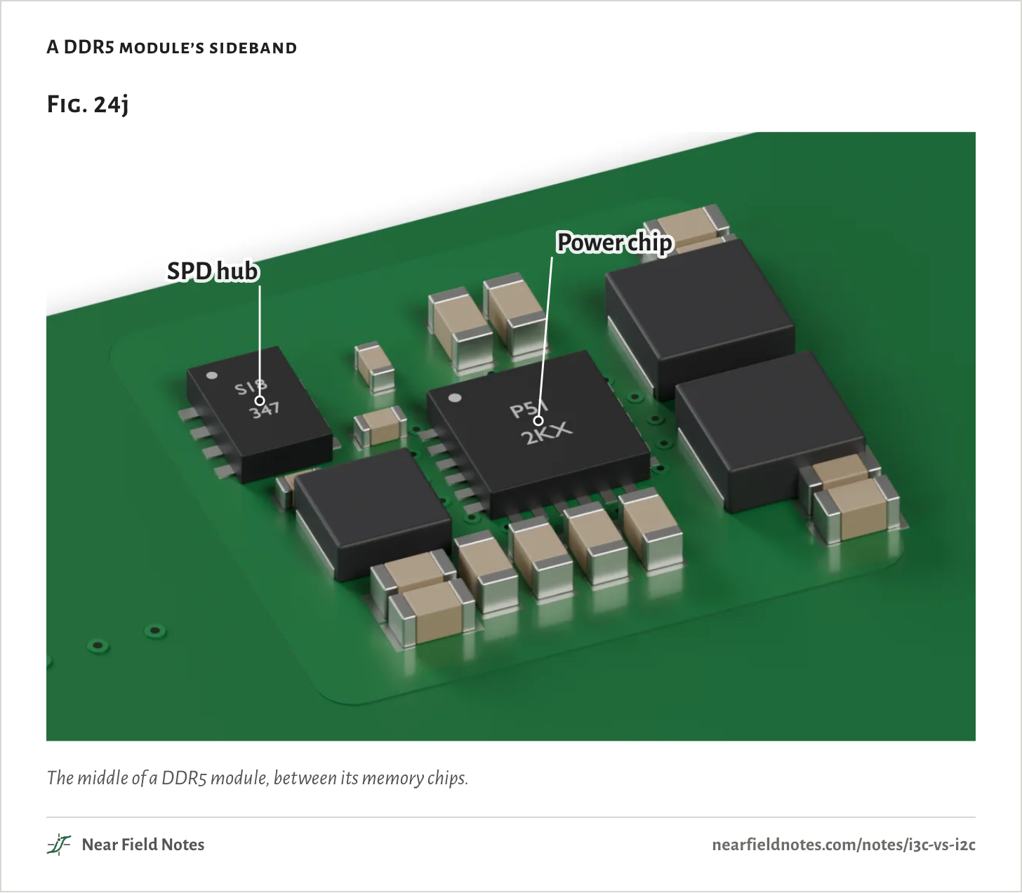
DDR5 memory modules carry a sideband bus that JEDEC built on I3C Basic. It links the SPD hub, which describes the module and reads its temperature, to the power chip and temperature sensors, and it keeps I3C’s full 12.5 MHz. Rambus’s SPD5118 hub runs at up to 1 MHz on I2C and 12.5 MHz on I3C Basic. Linux reads these hubs over I3C from version 7.3.

In servers, DMTF’s MCTP binding carries management packets over I3C, and OCP’s DC-SCM 2.2 module runs its management ports as I2C or I3C. Microcontrollers such as ST’s STM32H5 and Microchip’s PIC18-Q20 have I3C ports, and sensors such as TDK’s ICM-42688-P and Bosch’s BMI323 speak it at 12.5 MHz.

A DDR5 module’s sideband
Fig. 24jSPD hubPower chipFig. 24jSPD hubPower chipFig. 24jSPD hubPower chip
The middle of a DDR5 module, between its memory chips.

Why I2C isn’t gone

The catches

I3C hasn’t replaced I2C. Fewer chips speak it, and fewer tools read it. Saleae’s Logic 2 decodes it only through a paid plugin from another company, and sigrok’s open decoders have none.

A mixed bus runs only as fast as its slowest unfiltered I2C chip allows, and two copies of one part still need a pin or a fuse to tell them apart. For a sensor read once a second, I2C is fine: at 400 kHz the read keeps the bus busy 0.03% of the time.

Side by side

Fig. 24k

I2CI3C
WiresSCL and SDASCL and SDA
Clock100 kHz, 400 kHz or 1 MHz12.5 MHz in SDR
Lines go highThrough a pull-upDriven, open drain only to arbitrate and acknowledge
AddressesFixed 7-bit, a pin or two to changeHanded out by the controller
InterruptsA line for each chipOver SDA, lowest address first
12-byte read344 µs, 203 nJ at 400 kHz13.1 µs, 28.2 nJ
Shares its bus withAny I2C chipI2C targets with a 50 ns filter
Saleae Logic 2Built inPaid plugin
The read’s times and energies are Fig. 24f’s. The rest is from UM10204, MIPI’s FAQ and Saleae’s list of decoders.

Which bus for your sensors?

From the controller out

The key starts at the controller, because a bus can only be I3C if its controller is.

Key to sensor buses

I2C, I3C, or I3C held to I2C speed?

  1. 1aThe controller has no I3C port, or no sensor speaks I3CI2C, at the speed every chip allows
  2. 1bThe controller and some sensors speak I3CGo to 2
  3. 2aAn I2C chip on the bus has no 50 ns filterGo to 3
  4. 2bEvery I2C chip on the bus filters, or there are noneGo to 4
  5. 3aA spare pin pair can give that chip its own busI3C, with the old chip on I2C beside it
  6. 3bIt has to shareI3C held to I2C speed
  7. 4aReads are rare and pins are spareEither: I2C has more tools
  8. 4bReads are frequent, sensors many, or pins shortI3C at 12.5 MHz

An I2C chip that stretches the clock can’t share an I3C bus at all, by MIPI’s FAQ. It needs a bus of its own, as in 3a.

Time a read yourself

Four buses, 1 to 48 bytes

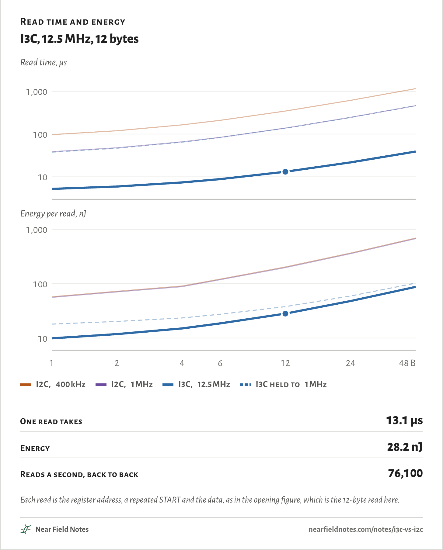
Pick a bus and how many data bytes one read carries. Both charts show all four buses, with the one you pick drawn bold, and both scales are logarithmic. Where two lines lie on top of each other, those two buses take the same.

Bus
12 bytes
Read time and energy

I3C, 12.5 MHz, 12 bytes

Read time, µs101001,000Energy per read, nJ101001,000141248 BRead time, µs101001,000Energy per read, nJ101001,0001246122448 BRead time, µs101001,000Energy per read, nJ101001,0001246122448 B
  • I2C, 400 kHz
  • I2C, 1 MHz
  • I3C, 12.5 MHz
  • I3C held to 1 MHz
One read takes
13.1 µs
Energy
28.2 nJ
Reads a second, back to back
76,100
Each read is the register address, a repeated START and the data, as in the opening figure, which is the 12-byte read here.
The numbers
Time and energy for one read.
Data bytesI2C, 400 kHzI2C, 1 MHzI3C, 12.5 MHzI3C held to 1 MHz
196.9 µs, 57.5 nJ38.8 µs, 56.0 nJ5.22 µs, 9.88 nJ37.7 µs, 18.1 nJ
2119 µs, 72.4 nJ47.8 µs, 70.6 nJ5.94 µs, 11.8 nJ46.7 µs, 20.2 nJ
4164 µs, 90.7 nJ65.8 µs, 88.3 nJ7.38 µs, 15.1 nJ64.7 µs, 23.5 nJ
6209 µs, 122 nJ83.8 µs, 118 nJ8.82 µs, 18.6 nJ82.7 µs, 27.4 nJ
12344 µs, 203 nJ138 µs, 198 nJ13.1 µs, 28.2 nJ137 µs, 37.9 nJ
24614 µs, 366 nJ246 µs, 357 nJ21.8 µs, 48.0 nJ245 µs, 59.5 nJ
481,154 µs, 692 nJ462 µs, 674 nJ39.1 µs, 87.6 nJ461 µs, 103 nJ

Conditions

Method
Circuit simulation in ngspice of one controller and one target on two lines, energy from the 1.8 V supply.
Lines
Each line 50 pF, driven through 50 Ω switches.
I2C
The weakest pull-up each speed allows on 50 pF: 7.08 kΩ at 400 kHz, 2.83 kΩ at 1 MHz. Clock low and setup times at the spec’s minimums.
I3C
SCL driven both ways, 40 ns low and 40 ns high. SDA open drain through 2.2 kΩ for the address after START and the acknowledges, 200 ns low and 40 ns high, with a 100 kΩ keeper.
The read
Address 0x68, register 0x1F, a repeated START and 12 data bytes, an IMU’s accelerometer and gyro sample. Each time runs from START to the end of the bus-free time after STOP.
Interrupt
Two targets at 0x09 and 0x0A, both open drain on the same SDA.
Filter
A digital 50 ns filter on the simulated SCL, switching only after a level has held 50 ns.
Renders
Blender, one board built for the picture with every trace routed, and a DDR5 module.

The board’s parts and traces are drawn for the picture, not taken from a product.

Limits

  • The I3C Basic spec itself sits behind a download form and wasn’t read. Its timings here come from MIPI’s FAQ and from ST’s and Microchip’s manuals.
  • Real chips add their own pin capacitance and drivers, which move every number here.
  • MIPI’s 4.3 times is for 1 kB against I2C at 1 MHz. The 7.2 times here is for 12 bytes against 400 kHz.
  • No public source here names a phone that ships with I3C.
  • HDR modes weren’t simulated.

Files

  • sim/bus.pyThe 12-byte read on I2C and I3C
  • sim/extra.pyThe interrupt, the 50 ns filter and I3C at 1 MHz
  • sim/bus_random.pyThe read with 30 random payloads
  • sim/site.pyReads of 1 to 48 bytes, and each read’s energy as it goes
  • render/board.pyThe board in Fig. 24
  • render/dimm.pyThe DDR5 module in Fig. 24j
  • render/site.pyBoth on a white ground
  • refs/research.mdThe research notes behind the sources

Sources

Like this note?

Rev 1 ·
  1. Rev 1First published

Each fix gets a line here, with the reader's name if they want credit.

Did it answer your question?

Want more on this?

Report a problem

What should the next note be? Ask for one