Near Field Notes

Note 12PowerRev 1Watch the video · 2:14

Power inductors

Does it matter how a 4.7 µH inductor is built?

Yes. Built five common ways, the same 4.7 µH puts anywhere from 0.44 mV to 7.5 mV on a trace 1 mm away, and loses 30% of its inductance at anywhere from 0.18 A to 4.7 A. How it’s built decides where its field goes and how much current it takes.

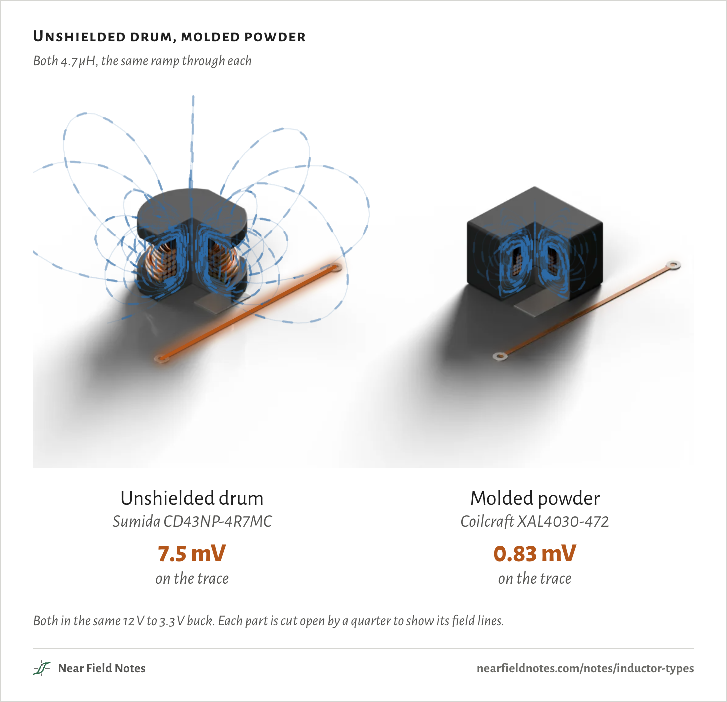
The figure runs the same current ramp through two of them. The lines are the simulated field, darker where it’s stronger, and each trace glows with the voltage it picks up.

The unshielded drum’s field loops out over the board. The molded powder part’s stays in its block, and its trace picks up a ninth as much.

Unshielded drum, molded powder

Both 4.7 µH, the same ramp through each

Unshielded drumSumida CD43NP-4R7MC7.5 mVon the traceMolded powderCoilcraft XAL4030-4720.83 mVon the traceUnshielded drumSumida CD43NP-4R7MC7.5 mVon the traceMolded powderCoilcraft XAL4030-4720.83 mVon the traceUnshielded drumSumida CD43NP-4R7MC7.5 mVon the traceMolded powderCoilcraft XAL4030-4720.83 mVon the trace

Both in the same 12 V to 3.3 V buck. Each part is cut open by a quarter to show its field lines.

Five 4.7 µH inductors

Cut open, at true size

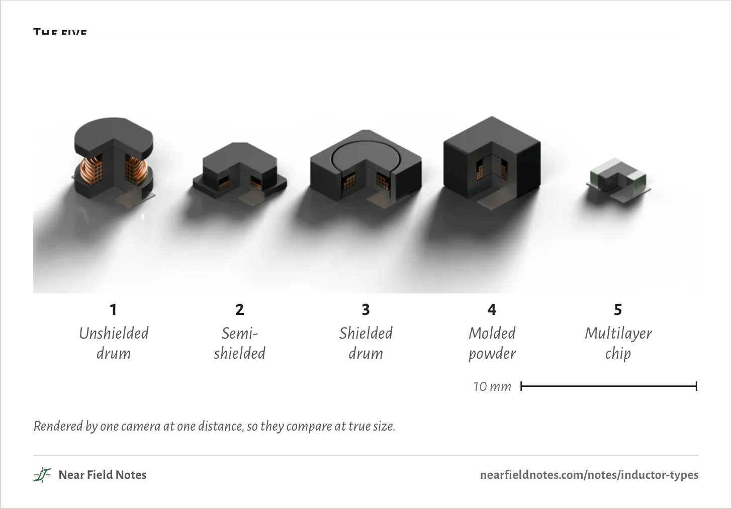
Power inductors come in five common builds. These are real parts of each, all 4.7 µH. Three are ferrite drums, one bare, one with magnetic resin around its winding and one inside a ferrite ring. The other two are a coil molded into metal powder and a coil printed between layers of ferrite.

Each is modeled from its datasheet’s outline. Makers don’t publish the insides, so the post, winding and materials are estimates, and each model’s turns are set so it simulates 4.70 µH.

The five
Fig. 12123451 Unshielded drum2 Semi-shielded drum3 Shielded drum4 Molded powder5 Multilayer chip10 mmFig. 121Unshieldeddrum2Semi-shielded3Shieldeddrum4Moldedpowder5Multilayerchip10 mmFig. 121Unshieldeddrum2Semi-shielded3Shieldeddrum4Moldedpowder5Multilayerchip10 mm

Rendered by one camera at one distance, so they compare at true size.

The circuit

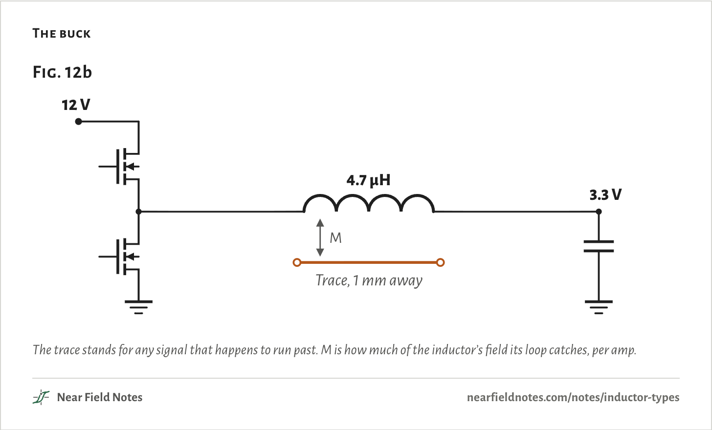
A 12 V to 3.3 V buck

Each part sits in the same buck converter, making 3.3 V from 12 V. While the top switch is on, the inductor has 8.7 V across it, and its current climbs 1.85 A every µs.

A signal trace runs past the part, 1 mm from its body and 10 mm long, with its return in the ground plane 0.2 mm below. Some of the inductor’s field passes between the trace and the plane. That couples the two through a mutual inductance, M.

The buck
Fig. 12b12 V4.7 µH3.3 VTrace, 1 mm awayMFig. 12b12 V4.7 µH3.3 VTrace, 1 mm awayMFig. 12b12 V4.7 µH3.3 VTrace, 1 mm awayM

The trace stands for any signal that happens to run past. M is how much of the inductor’s field its loop catches, per amp.

The voltage on the trace

Where the field crosses it

A changing current in the inductor puts a voltage on the trace:

V=MdIdt

=7.5 mVfor the unshielded drum,0.83 mVfor the molded powder part

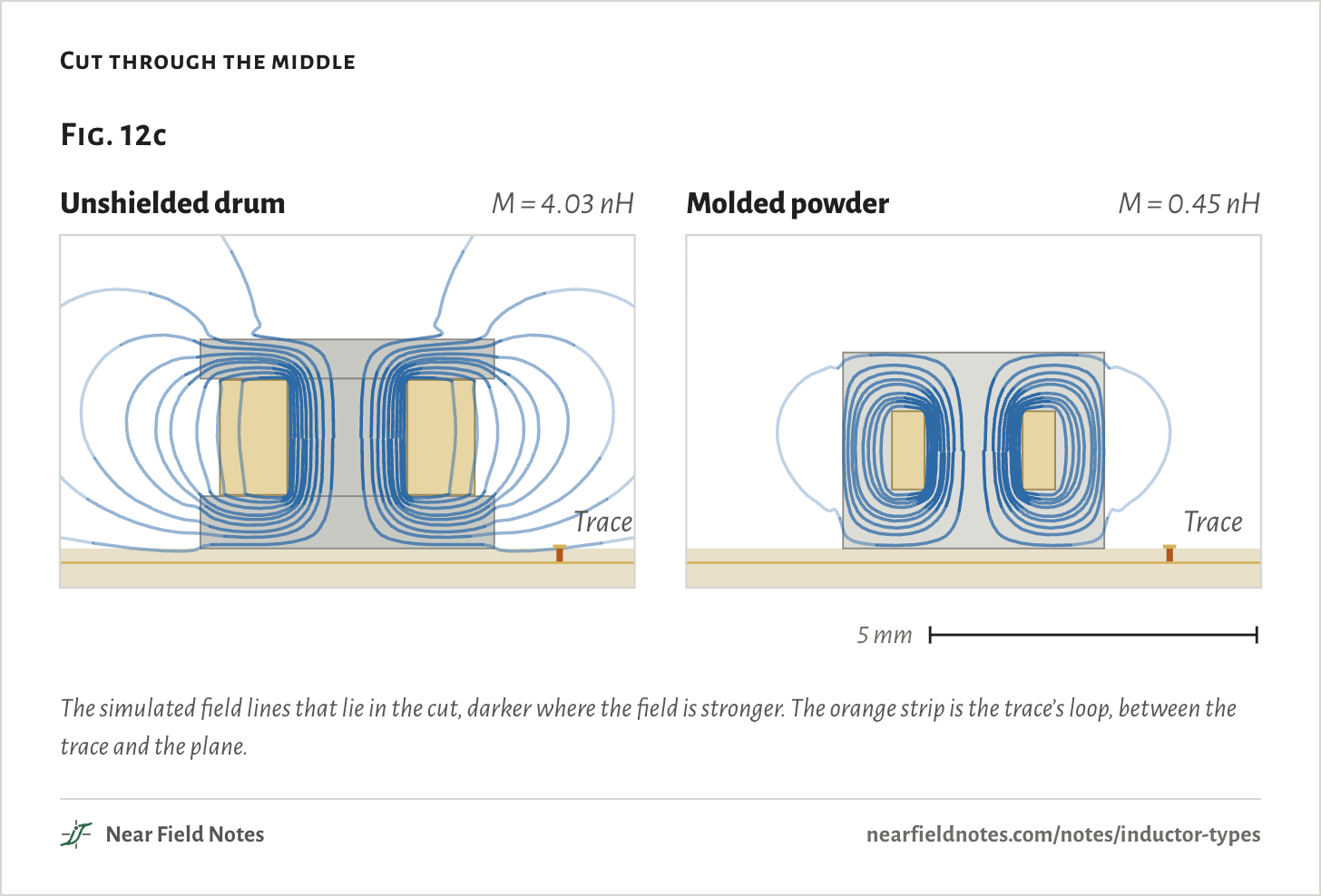
The current’s slope is the same for every part, so M decides. It counts the field that crosses the thin strip between the trace and the plane.

Cut through the middle, the unshielded drum’s field leaves its flanges and arcs back through the air, and some of it crosses that strip. The molded powder part’s field closes inside its block, and little reaches the trace.

Cut through the middle
Fig. 12cUnshielded drumM = 4.03 nHTraceMolded powderM = 0.45 nHTrace2 mmFig. 12cUnshielded drumM = 4.03 nHTraceMolded powderM = 0.45 nHTrace2 mmFig. 12cUnshielded drumM = 4.03 nHTraceMolded powderM = 0.45 nHTrace5 mm

The simulated field lines that lie in the cut, darker where the field is stronger. The orange strip is the trace’s loop, between the trace and the plane.

Unshielded drum

Sumida CD43NP-4R7MC

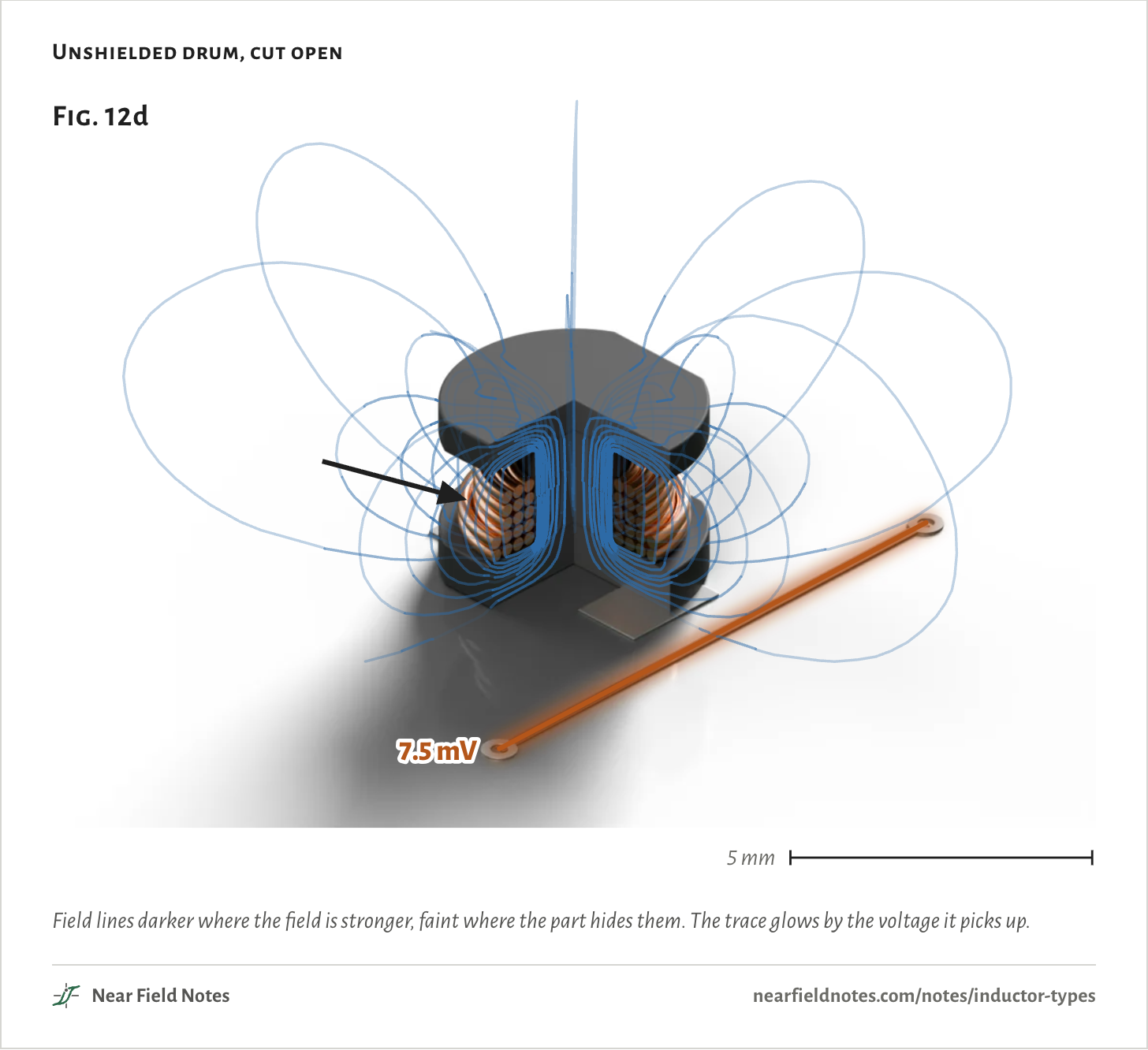
The plainest build is wire wound on a ferrite spool, open to the air between its flanges. Nothing carries the field from one flange back to the other, so it returns through the air around the part.

Unshielded drum, cut open
Fig. 12d7.5 mV5 mmFig. 12d7.5 mV5 mmFig. 12d7.5 mV5 mm

Field lines darker where the field is stronger, faint where the part hides them. The trace glows by the voltage it picks up.

268

Semi-shielded drum

Bourns SRN4018BTA-4R7M

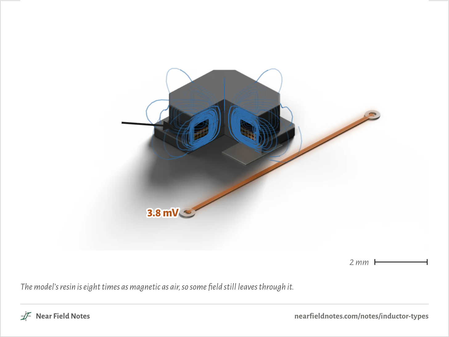
Filling the space between the flanges with resin full of magnetic powder gives the field part of a path back, outside the winding.

Semi-shielded drum, cut open
Fig. 12e3.8 mV2 mmFig. 12e3.8 mV2 mmFig. 12e3.8 mV2 mm

The model’s resin is eight times as magnetic as air, so some field still leaves through it.

270

Shielded drum

Bourns SRR4018-4R7Y

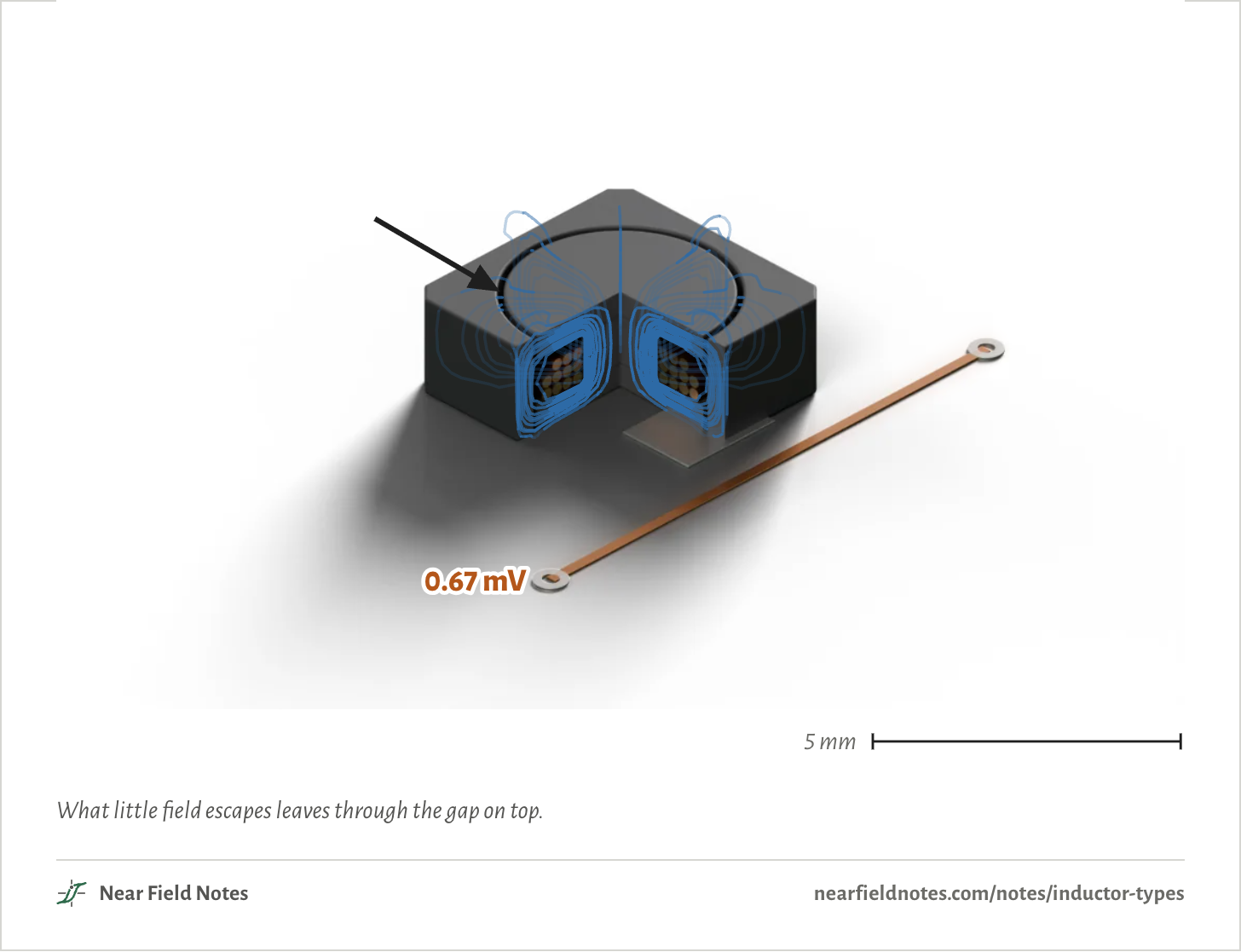
A ferrite ring around the drum closes the field’s path back. The only air left in it is a thin gap between the drum and the ring.

Shielded drum, cut open
Fig. 12f0.67 mV5 mmFig. 12f0.67 mV5 mmFig. 12f0.67 mV5 mm

What little field escapes leaves through the gap on top.

272

Molded powder

Coilcraft XAL4030-472

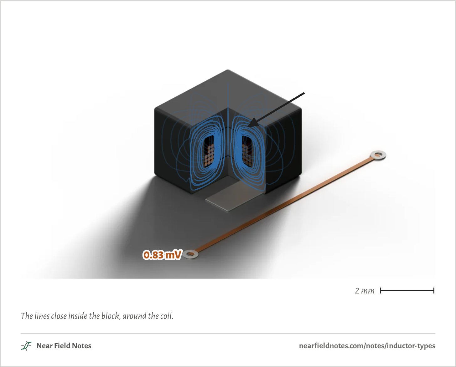
Pressing the coil inside a block of metal powder and resin wraps the field’s whole path in magnetic material. The resin between the grains spreads the gap through the whole block.

Molded powder, cut open
Fig. 12g0.83 mV2 mmFig. 12g0.83 mV2 mmFig. 12g0.83 mV2 mm

The lines close inside the block, around the coil.

274

Multilayer chip

Murata LQM2HPN4R7MG0L

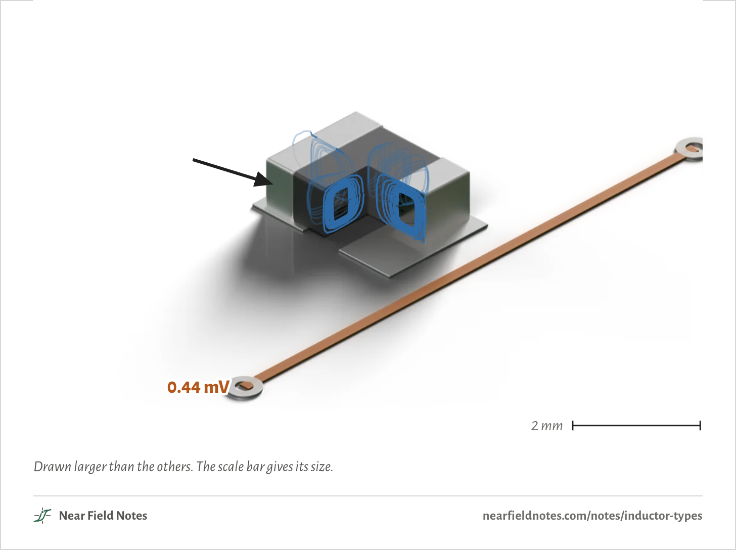
The smallest build prints the coil in silver on thin sheets of ferrite and stacks them into one chip, the turns joined through holes in the sheets.

Multilayer chip, cut open
Fig. 12h0.44 mV2 mmFig. 12h0.44 mV2 mmFig. 12h0.44 mV2 mm

Drawn larger than the others. The scale bar gives its size.

276

Noise on the trace

All five, in the same buck

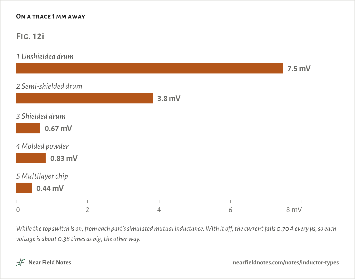
Side by side, the unshielded drum puts 9 times the molded powder part’s voltage on the trace, and 11 times the shielded drum’s. Resin around the winding halves it.

The three closed builds land within a factor of two of each other. The multilayer chip is the quietest, and the smallest.

On a trace 1 mm away
Fig. 12i1 Unshielded drum7.5 mV2 Semi-shielded drum3.8 mV3 Shielded drum0.67 mV4 Molded powder0.83 mV5 Multilayer chip0.44 mV02468 mVFig. 12i1 Unshielded drum7.5 mV2 Semi-shielded drum3.8 mV3 Shielded drum0.67 mV4 Molded powder0.83 mV5 Multilayer chip0.44 mV02468 mVFig. 12i1 Unshielded drum7.5 mV2 Semi-shielded drum3.8 mV3 Shielded drum0.67 mV4 Molded powder0.83 mV5 Multilayer chip0.44 mV02468 mV

While the top switch is on, from each part’s simulated mutual inductance. With it off, the current falls 0.70 A every µs, so each voltage is about 0.38 times as big, the other way.

Inductance under load

From each datasheet

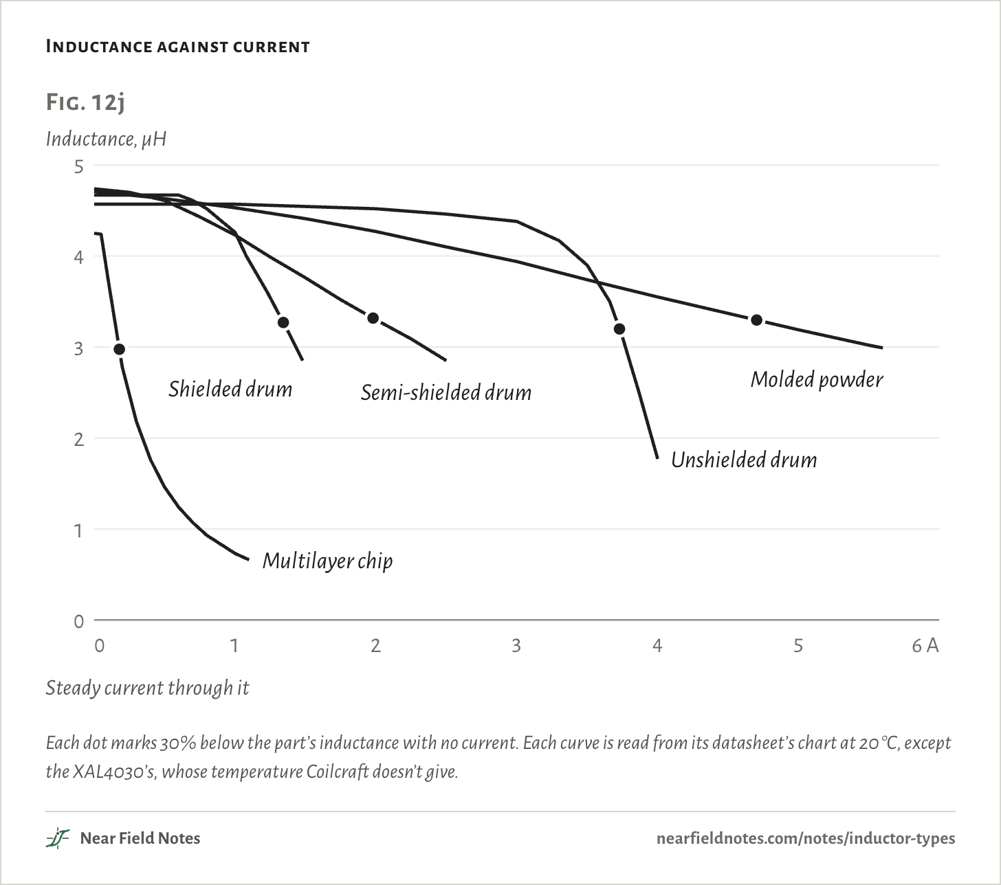
The other half of the choice is current. As the current through a part rises its core saturates, and its inductance falls.

The unshielded and shielded drums hold flat, then fall at a knee. The semi-shielded drum and the molded powder part slope the whole way. The multilayer chip falls steeply from the start.

Each datasheet defines its rated current its own way, so the curves compare better than the ratings.

Inductance against current
Fig. 12jInductance, µH0123450123456 ASteady current through it123451 Unshielded drum2 Semi-shielded drum3 Shielded drum4 Molded powder5 Multilayer chipFig. 12jInductance, µH0123450123456 ASteady current through itUnshielded drumSemi-shielded drumShielded drumMolded powderMultilayer chipFig. 12jInductance, µH0123450123456 ASteady current through itUnshielded drumSemi-shielded drumShielded drumMolded powderMultilayer chip

Each dot marks 30% below the part’s inductance with no current. Each curve is read from its datasheet’s chart at 20 °C, except the XAL4030’s, whose temperature Coilcraft doesn’t give.

Side by side

The five in numbers
The five
BuildPartSize, mmOn the trace30% down atRatedResistancePrice
1 Unshielded drumSumida CD43NP-4R7MC4.5 × 4.0 × 3.27.5 mV3.7 A1.62 A108.7 mΩ max$1.58
2 Semi-shielded drumBourns SRN4018BTA-4R7M4.0 × 4.0 × 1.63.8 mV2.0 A1.7 A70 mΩ$0.42
3 Shielded drumBourns SRR4018-4R7Y4.8 × 4.8 × 1.80.67 mV1.3 A1.72 A82 mΩ max$0.65
4 Molded powderCoilcraft XAL4030-4724.0 × 4.0 × 3.10.83 mV4.7 A3.9 A40.1 mΩ$2.18
5 Multilayer chipMurata LQM2HPN4R7MG0L2.5 × 2.0 × 0.90.44 mV0.18 A1.1 A110 mΩ$0.28

Rated currents as each maker defines them. Prices for one part on 3 November 2026, from Digi-Key or Mouser.

If something sensitive sits close, skip the unshielded drum. If the current is high, the molded powder part holds its inductance best. The multilayer chip suits only small currents.

Conditions

Parts
Sumida CD43NP-4R7MC, Bourns SRN4018BTA-4R7M, Bourns SRR4018-4R7Y, Coilcraft XAL4030-472 and Murata LQM2HPN4R7MG0L, all 4.7 µH, with outlines from their datasheets
Models
Posts, windings and the ring’s gap estimated, with permeabilities of 200 for the drums’ and the ring’s ferrite, 8 for the magnetic resin, 30 for the metal powder and 100 for the multilayer’s ferrite. Each model’s turns set so it simulates 4.70 µH.
Board
A ground plane 0.2 mm under the top copper, a perfect conductor at the ripple’s frequency
Trace
10 mm long, 1 mm from the body’s side, centered on the part, its return in the plane
Buck
12 V to 3.3 V. While the top switch is on, the current climbs 1.85 A every µs.
Curves
Read by eye from each datasheet’s chart of inductance against current, at 20 °C, except the XAL4030’s, whose temperature Coilcraft doesn’t give
Solver
Elmer, 3D magnetostatics at 1 A. An air coil checks it: 0.896 µH against Wheeler’s formula’s 0.906 µH.

Simulated only. Nothing on this page has been measured on a board yet.

Limits

  • The insides are estimates, and real ones will move each number. The ring’s gap, for one, is taken as 0.1 mm, from a patent’s range of 0.1 to 0.5 mm.
  • The materials are linear, so the field is the one at low current, before any core saturates.
  • Only the magnetic field is counted. The switch node’s voltage also reaches nearby traces through its electric field.
  • Ratings are defined differently. The CD43’s is the lower of a 10% drop and a 40 °C rise. The others are a 20, 30 or 40 °C rise.
  • The CD43’s 1.62 A rating sits below every limit its own charts show.

Files

  • sim/parts.pyThe five models’ sizes, turns and permeabilities
  • sim/run.pyThe Elmer solve and each model’s inductance
  • sim/lines.pyThe field lines, traced through the solved field
  • sim/noise.pyThe trace’s mutual inductance and voltage
  • render/scene.pyThe renders, and the lines projected into them

Sources

Like this note?

Rev 1 ·
  1. Rev 1First published

Each fix gets a line here, with the reader's name if they want credit.

Did it answer your question?

Want more on this?

Report a problem

What should the next note be? Ask for one