Near Field Notes

Note 29Signal integrityRev 1Watch the video · 2:42

CSI trios

How do C-PHY trios carry a camera’s video, and how do they compare with regular CSI?

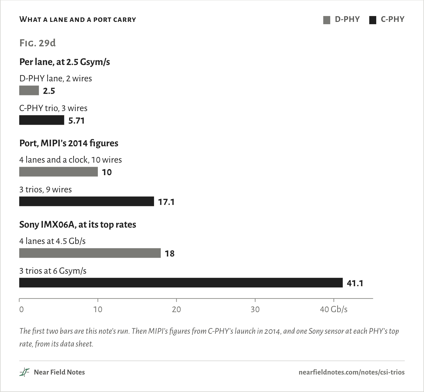
A trio drives its three wires to three different levels and changes the pattern every symbol, so its receiver takes the clock from the data and 16 bits ride in every 7 symbols. Regular CSI runs on D-PHY, which sends one bit per symbol on each wire pair and the clock on a pair of its own. At the same 2.5 Gsym/s on 15 cm of flex, a trio carries 5.71 Gb/s on three wires and a D-PHY lane 2.5 Gb/s on two.

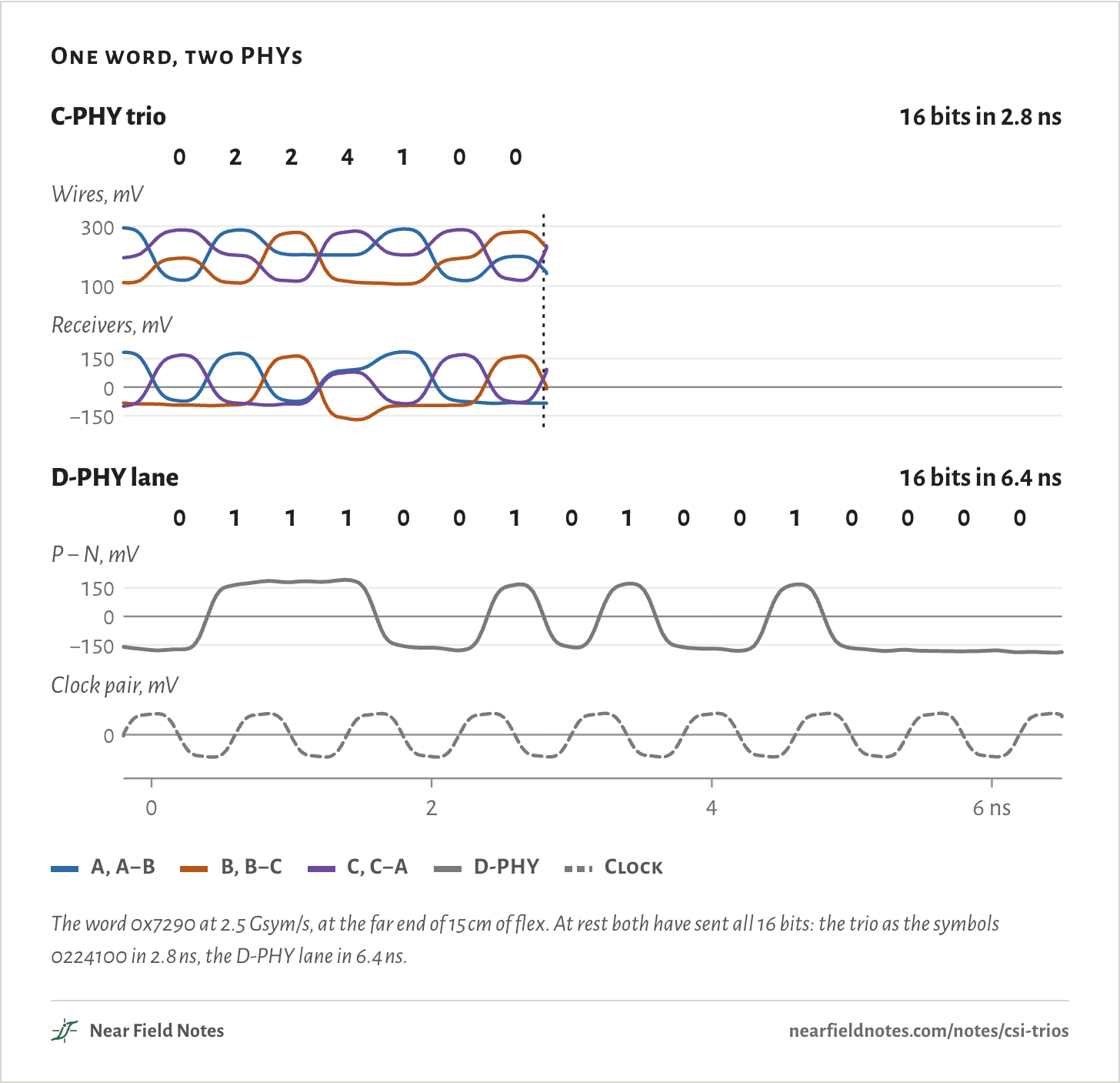
The figure sends one 16-bit word both ways. The trio uses the one entry of the spec’s word table that is public, and it is done in 2.8 ns, before the D-PHY lane is halfway through.

One word, two PHYs
C-PHY trio16 bits in 2.8 ns100300Wires, mV−1500150Receivers, mVD-PHY lane16 bits in 6.4 ns−1500150P − N, mV0Clock pair, mV0246 ns02241000111001010010000C-PHY trio16 bits in 2.8 ns100300Wires, mV−1500150Receivers, mVD-PHY lane16 bits in 6.4 ns−1500150P − N, mV0Clock pair, mV0246 ns02241000111001010010000C-PHY trio16 bits in 2.8 ns100300Wires, mV−1500150Receivers, mVD-PHY lane16 bits in 6.4 ns−1500150P − N, mV0Clock pair, mV0246 ns02241000111001010010000
  • A, A−B
  • B, B−C
  • C, C−A
  • D-PHY
  • Clock
The word 0x7290 at 2.5 Gsym/s, at the far end of 15 cm of flex. At rest both have sent all 16 bits: the trio as the symbols 0224100 in 2.8 ns, the D-PHY lane in 6.4 ns.
The numbers
The word 0x7290 at 2.5 Gsym/s on each.
LaneWiresSent asTakes
C-PHY trio37 symbols: 0 2 2 4 1 0 02.8 ns
D-PHY lane2, and 2 for the clock16 bits: 0 1 1 1 0 0 1 0 1 0 0 1 0 0 0 06.4 ns

A camera on a flex

10 wires, or 9

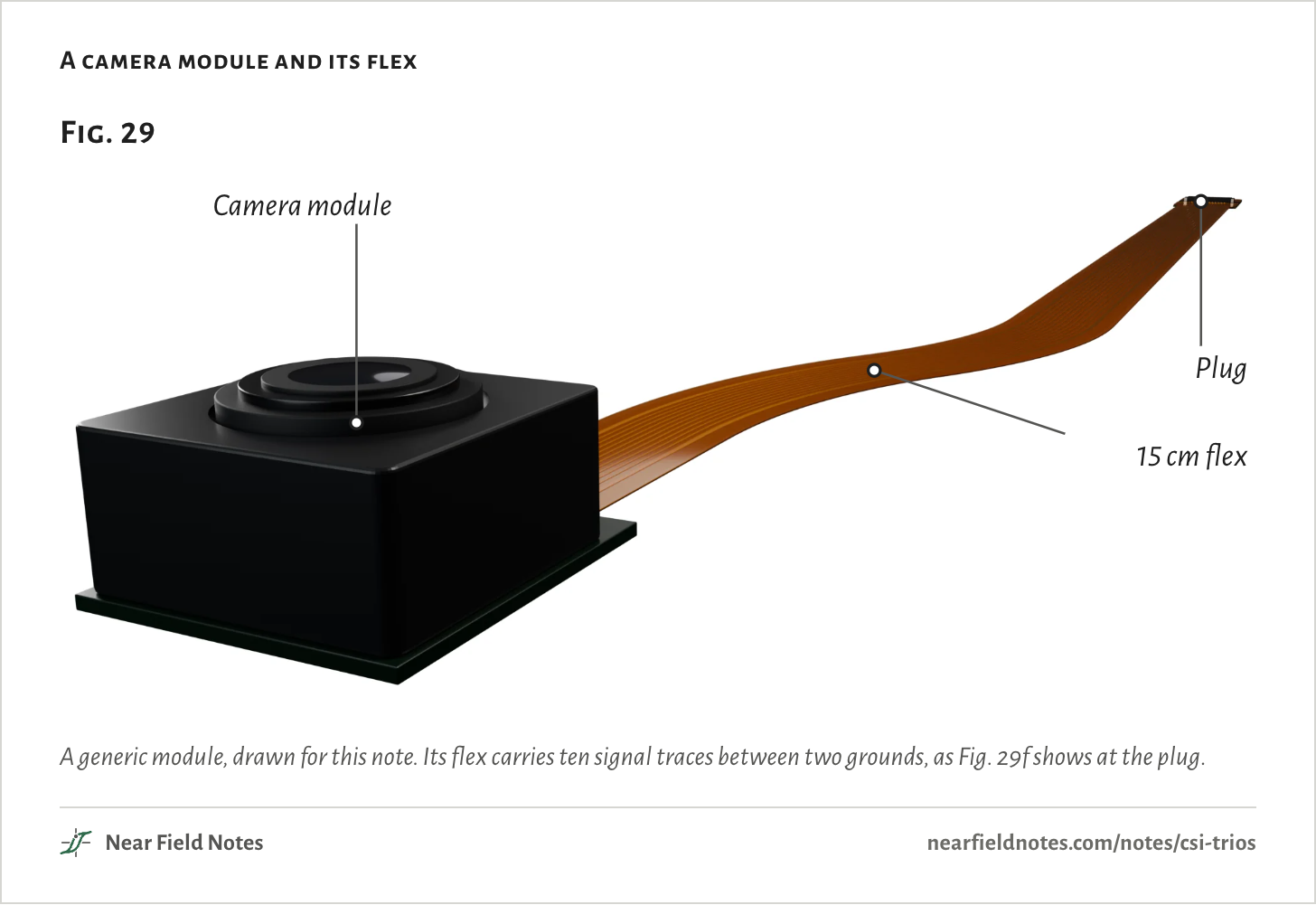
A phone camera is an image sensor in a small module. Its pictures leave on a flex, a thin printed cable, for a plug on the main board. CSI-2 is MIPI’s camera protocol: it packs the pixels into packets, and a PHY underneath turns them into voltages on the wires. Note 14 sorts out which job is whose. A car camera can sit meters from its computer, so a serializer carries its CSI-2 data over coax, as Note 27 shows.

CSI-2 runs on one of two PHYs. D-PHY, the older one, sends data on wire pairs. MIPI still calls it the predominant PHY for cameras. C-PHY sends data on trios, three wires that work as one lane.

A camera module and its flex
Fig. 29Camera modulePlug15 cm flexFig. 29Camera modulePlug15 cm flexFig. 29Camera modulePlug15 cm flex
A generic module, drawn for this note. Its flex carries ten signal traces between two grounds, as Fig. 29f shows at the plug.

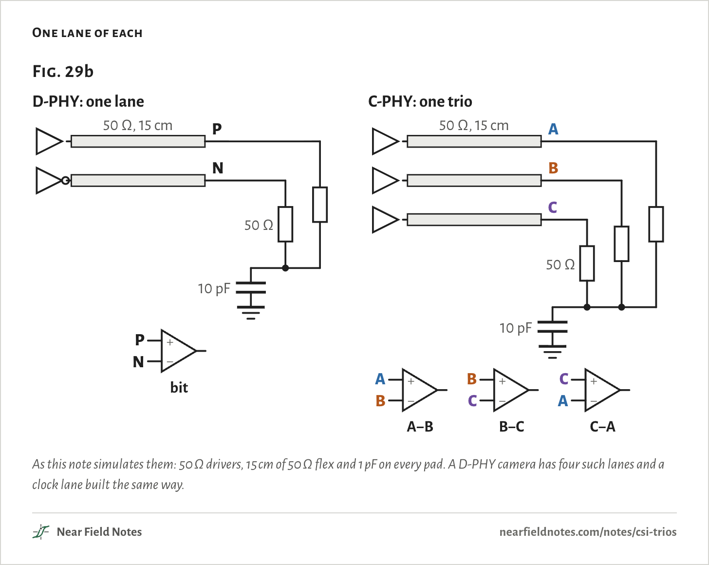
A D-PHY lane is a differential pair. One wire goes high as the other goes low, and the receiver reads the difference as a bit. The clock rides on a pair of its own, so a 4-lane camera needs 10 wires.

A trio’s three wires each have their own driver. At the far end each meets 50 Ω to one shared point, and three receivers compare the wires in pairs: A with B, B with C and C with A.

One lane of each
Fig. 29bD-PHY: one lanePN50 Ω, 15 cm10 pF50 Ω+−PNbitC-PHY: one trioABC50 Ω, 15 cm10 pF50 Ω+−ABA−B+−BCB−C+−CAC−AFig. 29bD-PHY: one lanePN50 Ω, 15 cm10 pF50 Ω+−PNbitC-PHY: one trioABC50 Ω, 15 cm10 pF50 Ω+−ABA−B+−BCB−C+−CAC−AFig. 29bD-PHY: one lanePN50 Ω, 15 cm10 pF50 Ω+−PNbitC-PHY: one trioABC50 Ω, 15 cm10 pF50 Ω+−ABA−B+−BCB−C+−CAC−A
As this note simulates them: 50 Ω drivers, 15 cm of 50 Ω flex and 1 pF on every pad. A D-PHY camera has four such lanes and a clock lane built the same way.

Three wires, three levels

Six states

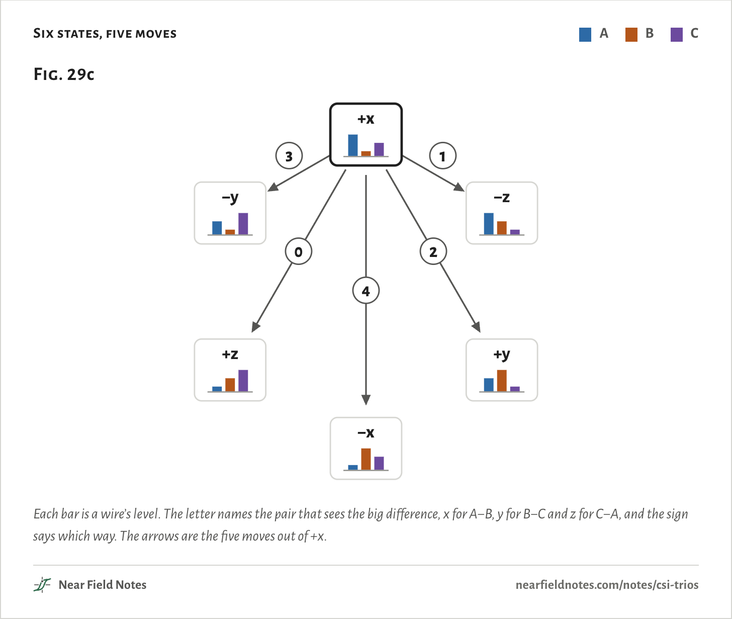
In every symbol a trio’s three wires sit at three different levels: one high, one low and one in the middle. There are six ways to arrange them, the six wire states, and each symbol moves the trio from one to another.

Six states, five moves
  • A
  • B
  • C
Fig. 29c12403+x−z+y−x+z−yFig. 29c12403+x−z+y−x+z−yFig. 29c12403+x−z+y−x+z−y
Each bar is a wire’s level. The letter names the pair that sees the big difference, x for A−B, y for B−C and z for C−A, and the sign says which way. The arrows are the five moves out of +x.
The numbers
Wire levels at the far end are about 107, 199 and 294 mV. Receiver voltages are the middle value at the sampling instant over the run. The last five columns are the state each symbol leads to.
StateABCA−B, mVB−C, mVC−A, mV01234
+xHighLowMiddle+168−84−84+z−z+y−y−x
−xLowHighMiddle−168+84+84−z+z−y+y+x
+yMiddleHighLow−84+168−84+x−x+z−z−y
−yMiddleLowHigh+84−168+84−x+x−z+z+y
+zLowMiddleHigh−84−84+168+y−y+x−x−z
−zHighMiddleLow+84+84−168−y+y−x+x+z
554

Sixteen bits in seven symbols

16/7 of the symbol rate

The state has to change every symbol, so from any state there are five places to go. A symbol is one of those five moves, numbered 0 to 4. Seven symbols give enough patterns for every 16-bit word:

57=78,125≥216=65,536

So a trio carries 16 bits in every 7 symbols, and its data rate is

Rb=Rs×167

5.71 Gb/s=2.5 Gsym/s×167

A D-PHY lane carries one bit per symbol, 2.5 Gb/s at the same rate.

What a lane and a port carry
  • D-PHY
  • C-PHY
Fig. 29dPer lane, at 2.5 Gsym/sD-PHY lane, 2 wires2.5C-PHY trio, 3 wires5.71Port, MIPI’s 2014 figures4 lanes and a clock, 10 wires103 trios, 9 wires17.1Sony IMX06A, at its top rates4 lanes at 4.5 Gb/s183 trios at 6 Gsym/s41.1010203040 Gb/sFig. 29dPer lane, at 2.5 Gsym/sD-PHY lane, 2 wires2.5C-PHY trio, 3 wires5.71Port, MIPI’s 2014 figures4 lanes and a clock, 10 wires103 trios, 9 wires17.1Sony IMX06A, at its top rates4 lanes at 4.5 Gb/s183 trios at 6 Gsym/s41.1010203040 Gb/sFig. 29dPer lane, at 2.5 Gsym/sD-PHY lane, 2 wires2.5C-PHY trio, 3 wires5.71Port, MIPI’s 2014 figures4 lanes and a clock, 10 wires103 trios, 9 wires17.1Sony IMX06A, at its top rates4 lanes at 4.5 Gb/s183 trios at 6 Gsym/s41.1010203040 Gb/s
The first two bars are this note’s run. Then MIPI’s figures from C-PHY’s launch in 2014, and one Sony sensor at each PHY’s top rate, from its data sheet.
The numbers
A trio carries 16 bits in 7 symbols, so its data rate is 16/7 of its symbol rate.
Data rateFrom
D-PHY lane, 2 wires2.5 Gb/sThis note’s run
C-PHY trio, 3 wires5.71 Gb/sThis note’s run
4 lanes and a clock, 10 wires10 Gb/sMIPI press release, 2014
3 trios, 9 wires17.1 Gb/sMIPI press release, 2014
4 lanes at 4.5 Gb/s18 Gb/sSony IMX06A data sheet
3 trios at 6 Gsym/s41.1 Gb/sSony IMX06A data sheet
556

The clock is in the edges

No clock wires

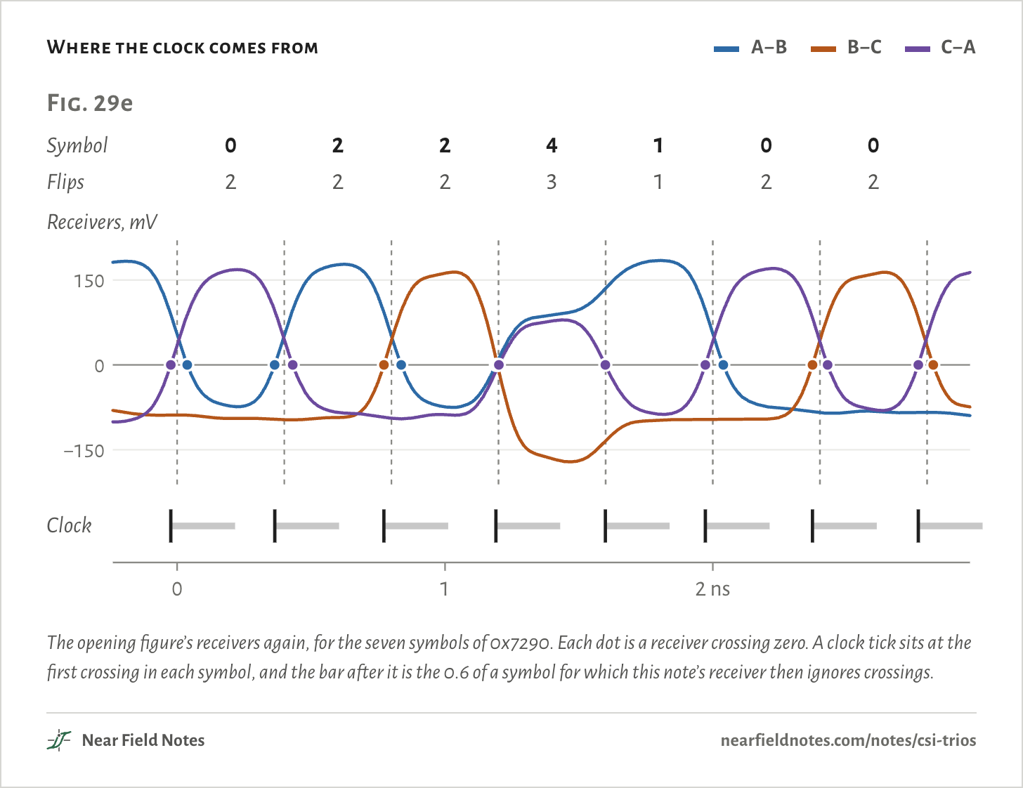
Because the state always changes, at least one receiver flips in every symbol. The receiver builds its clock from those flips, so a trio needs no clock wires.

Where the clock comes from
  • A−B
  • B−C
  • C−A
Fig. 29eSymbol0224100Flips2223122−1500150Receivers, mVClock012 nsFig. 29eSymbol0224100Flips2223122−1500150Receivers, mVClock012 nsFig. 29eSymbol0224100Flips2223122−1500150Receivers, mVClock012 ns
The opening figure’s receivers again, for the seven symbols of 0x7290. Each dot is a receiver crossing zero. A clock tick sits at the first crossing in each symbol, and the bar after it is the 0.6 of a symbol for which this note’s receiver then ignores crossings.
The numbers
Crossings are timed from where the symbol's edge is centered at the receiver.
SymbolMoveReceivers that flipTheir crossings, from the symbol edge
0+x to +z2−23 ps, 38 ps
2+z to +x2−36 ps, 32 ps
2+x to +y2−28 ps, 36 ps
4+y to −y3−9.9 ps, −4.3 ps, 1.4 ps
1−y to +x1−1.3 ps
0+x to +z2−28 ps, 39 ps
0+z to +y2−28 ps, 28 ps
558

The same ten pins

One left over

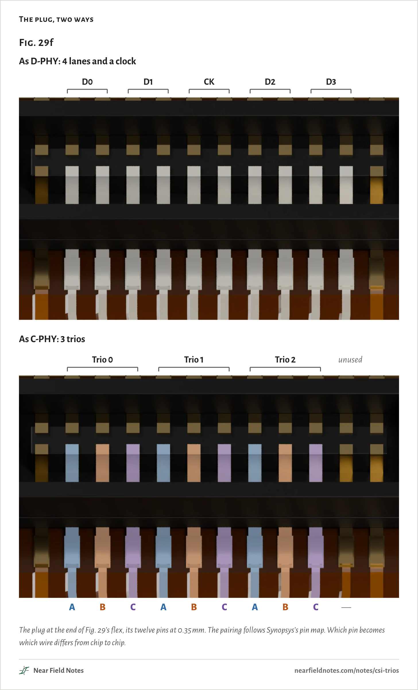
Four D-PHY lanes and their clock use 10 pins. Three trios use 9. Chips that speak both put them on the same pins, so one board can take either kind of camera.

Qualcomm’s QCS6490 names one ball CSI0_A0_CLK_M: the D-PHY clock’s minus wire, or wire A of trio 0. Rockchip’s RK3588 names its tenth pin MIPI_DPHY0_RX_D3P/NO_USE. NVIDIA rates its Jetson AGX Orin at 40 Gb/s of camera input as D-PHY and 164 Gb/s as C-PHY, on the same pins.

The plug, two ways
Fig. 29fAs D-PHY: 4 lanes and a clockD0D1CKD2D3As C-PHY: 3 triosTrio 0Trio 1Trio 2ABCABCABC—unusedFig. 29fAs D-PHY: 4 lanes and a clockD0D1CKD2D3As C-PHY: 3 triosTrio 0Trio 1Trio 2ABCABCABC—unusedFig. 29fAs D-PHY: 4 lanes and a clockD0D1CKD2D3As C-PHY: 3 triosTrio 0Trio 1Trio 2ABCABCABC—unused
The plug at the end of Fig. 29’s flex, its twelve pins at 0.35 mm. The pairing follows Synopsys’s pin map. Which pin becomes which wire differs from chip to chip.
The numbers
Pins counted between the two grounds. The pairing is Synopsys’s combo PHY pin map.
PinAs D-PHYAs C-PHY
1D0PTrio 0, A
2D0NTrio 0, B
3D1PTrio 0, C
4D1NTrio 1, A
5CKPTrio 1, B
6CKNTrio 1, C
7D2PTrio 2, A
8D2NTrio 2, B
9D3PTrio 2, C
10D3NUnused

A smaller eye

133 mV against 308 mV

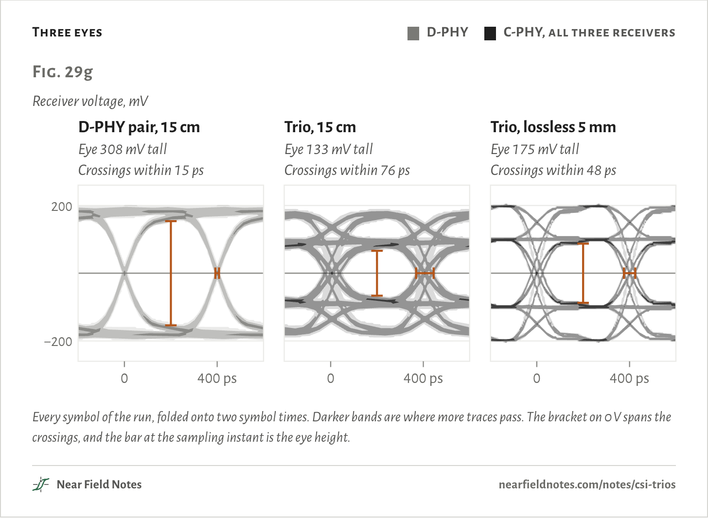
The trio pays for its speed in margin. Its receivers see steps of two sizes, and they cross zero at different times. Note 8 shows how to read an eye diagram.

Three eyes
  • D-PHY
  • C-PHY, all three receivers
Fig. 29gReceiver voltage, mVD-PHY pair, 15 cmEye 308 mV tallCrossings within 15 ps0400 ps−200200Trio, 15 cmEye 133 mV tallCrossings within 76 ps0400 ps−200200Trio, lossless 5 mmEye 175 mV tallCrossings within 48 ps0400 ps−200200Fig. 29gReceiver voltage, mVD-PHY pair, 15 cmEye 308 mV tallCrossings within 15 ps0400 ps−200200Trio, 15 cmEye 133 mV tallCrossings within 76 ps0400 ps−200200Trio, lossless 5 mmEye 175 mV tallCrossings within 48 ps0400 ps−200200Fig. 29gReceiver voltage, mVD-PHY pair, 15 cmEye 308 mV tallCrossings within 15 ps0400 ps−200200Trio, 15 cmEye 133 mV tallCrossings within 76 ps0400 psTrio, lossless 5 mmEye 175 mV tallCrossings within 48 ps0400 ps
Every symbol of the run, folded onto two symbol times. Darker bands are where more traces pass. The bracket on 0 V spans the crossings, and the bar at the sampling instant is the eye height.
The numbers
Eye height is twice the smallest receiver voltage at the sampling instant; eye width is the symbol time less the crossing spread.
Crossings spread overEye heightEye width
D-PHY pair, 15 cm15 ps308 mV385 ps
Trio, 15 cm76 ps133 mV324 ps
Trio, lossless 5 mm48 ps175 mV352 ps
560

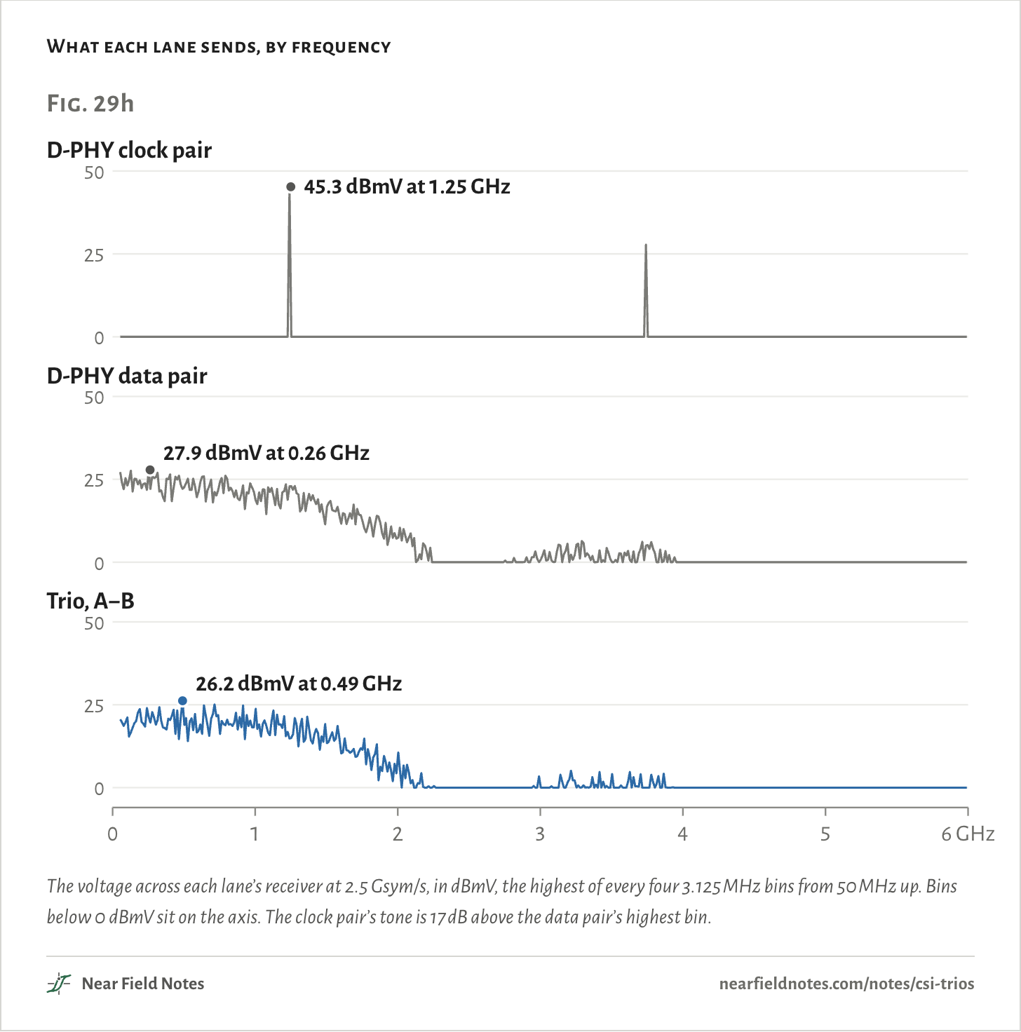
No clock tone

One tone, or none

A D-PHY clock pair sends 1010 over and over, so its energy piles into one frequency, half the bit rate. Data spreads its energy across the band. A trio has no clock pair.

What each lane sends, by frequency
Fig. 29hD-PHY clock pair0255045.3 dBmV at 1.25 GHzD-PHY data pair0255027.9 dBmV at 0.26 GHzTrio, A−B0255026.2 dBmV at 0.49 GHz0246 GHzFig. 29hD-PHY clock pair0255045.3 dBmV at 1.25 GHzD-PHY data pair0255027.9 dBmV at 0.26 GHzTrio, A−B0255026.2 dBmV at 0.49 GHz0123456 GHzFig. 29hD-PHY clock pair0255045.3 dBmV at 1.25 GHzD-PHY data pair0255027.9 dBmV at 0.26 GHzTrio, A−B0255026.2 dBmV at 0.49 GHz0123456 GHz
The voltage across each lane’s receiver at 2.5 Gsym/s, in dBmV, the highest of every four 3.125 MHz bins from 50 MHz up. Bins below 0 dBmV sit on the axis. The clock pair’s tone is 17 dB above the data pair’s highest bin.
The numbers
Common-mode current is the sum of a lane's wire currents, with one wire 5 ps late. Matched, it is below −50 dBµA on all three.
LaneHighest bin, receiver voltageHighest bin, common-mode current with 5 ps skew
D-PHY clock pair45.3 dBmV at 1.25 GHz41.7 dBµA at 1.25 GHz
D-PHY data pair27.9 dBmV at 0.26 GHz20.1 dBµA at 1.28 GHz
Trio, A−B26.2 dBmV at 0.49 GHz19.0 dBµA at 1.29 GHz
562

Routing a trio

Three pairs at once

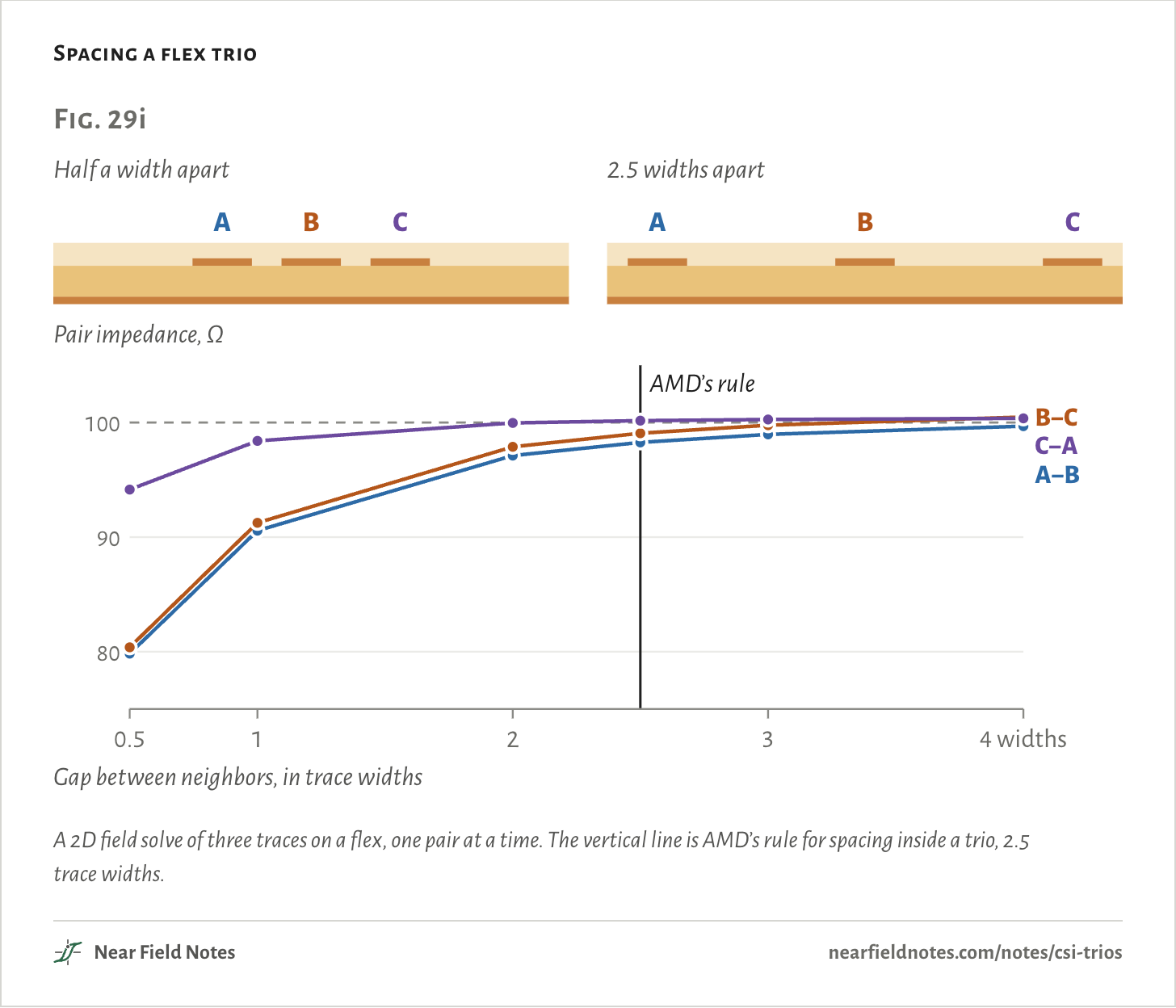
A trio is three pairs at once, A−B, B−C and C−A, and each should be 100 Ω, the impedance its receivers terminate. Laid side by side like a differential pair, the outer two wires are twice as far apart as the neighbors, and the three pairs drift apart.

Spacing a flex trio
Fig. 29iHalf a width apartABC2.5 widths apartABCPair impedance, Ω8090100AMD’s ruleB−CC−AA−B0.51234 widthsGap between neighbors, in trace widthsFig. 29iHalf a width apartABC2.5 widths apartABCPair impedance, Ω8090100AMD’s ruleB−CC−AA−B0.51234 widthsGap between neighbors, in trace widthsFig. 29iHalf a width apartABC2.5 widths apartABCPair impedance, Ω8090100AMD’s ruleB−CC−AA−B0.51234 widthsGap between neighbors, in trace widths
A 2D field solve of three traces on a flex, one pair at a time. The vertical line is AMD’s rule for spacing inside a trio, 2.5 trace widths.
The numbers
Traces 96 µm wide and 12 µm thick on 50 µm of polyimide over a ground plane, under 25 µm of coverlay.
Gap, widthsGap, µmA−B, ΩB−C, ΩC−A, Ω
0.54879.880.494.2
19690.691.398.4
219297.197.9100.0
2.524098.399.1100.2
328899.099.8100.3
438499.7100.5100.4
564

Who uses which

Most flagships offer both

Flagship phone sensors from Samsung, Sony and OmniVision offer both PHYs on the same pins, and the phone maker picks. Many processors have D-PHY alone, and even a combo port needs a driver that runs it as C-PHY.

Sensors

Fig. 29j

SensorD-PHYC-PHYSource
Sony IMX06A4 lanes, 4.5 Gb/s each3 trios, 6.0 Gsym/s eachData sheet
Sony LYTIA 9014 lanes, 2.5 Gb/s3 trios, 6.0 Gsym/sNews release
Samsung ISOCELL HP34 lanes, 2.5 Gb/s3 trios, 4.0 Gsym/sProduct page, archived
Samsung ISOCELL GN24 lanes, 6.5 Gb/s3 trios, 3.5 Gsym/sProduct page
Samsung ISOCELL JN14 lanes, 2.15 Gb/sNone listedProduct page, archived
OmniVision OV50H4 lanes, 3.0 Gb/s3 trios, 3.5 Gsym/sProduct page
Raspberry Pi Camera Module 32 lanesNoneLinux driver, imx708.c
Rates as each maker states them, at each PHY’s top. A trio’s data rate is 16/7 of its symbol rate, so Samsung’s GN2 is the faster on D-PHY: 26 against 24.0 Gb/s.
Processors

Fig. 29k

ProcessorD-PHYC-PHYSource
NVIDIA Jetson AGX Orin16 lanes, 40 Gb/s in all16 trios, 164 Gb/s in allData sheet
NVIDIA Jetson Orin NX and Orin Nano8 lanesNoneProduct page
Qualcomm QCS64904-lane ports3-trio ports, on the same ballsData sheet
Rockchip RK3588Six 4-lane portsTwo of them, 3 trios at 2.5 Gsym/sData sheet
MediaTek MT8395Three 4-lane portsIn the hardware, not in its ISP driverData sheet, Genio docs
Raspberry Pi 5Two 4-lane portsNoneRP1 data sheet
Camera inputs as each maker lists them. On the RK3588 two of the six ports are combo PHYs and four are D-PHY only.

Which PHY does my camera use?

Start at the sensor

The key starts at the sensor, because most offer both and a few offer one.

Key to camera PHYs

D-PHY, C-PHY or either?

  1. 1aThe sensor offers one PHY. Its pins name lanes and a clock, D0P and CKN, or trios, A0, B0 and C0The one it offers
  2. 1bIt offers both, on the same pinsGo to 2
  3. 2aThe processor’s camera port is D-PHY only, as on a Raspberry Pi or a Jetson Orin NXD-PHY
  4. 2bThe port is a combo PHYGo to 3
  5. 3aIts driver runs the port only as D-PHYD-PHY
  6. 3bIts driver runs C-PHYGo to 4
  7. 4aThe sensor’s D-PHY lanes reach the frame rate you needEither
  8. 4bOnly its trios doC-PHY

At 4, check the rates rather than assume. Sony’s IMX06A doubles its full-resolution frame rate on C-PHY, but Samsung’s GN2 is faster on D-PHY.

Step a trio yourself

6 states, 5 symbols

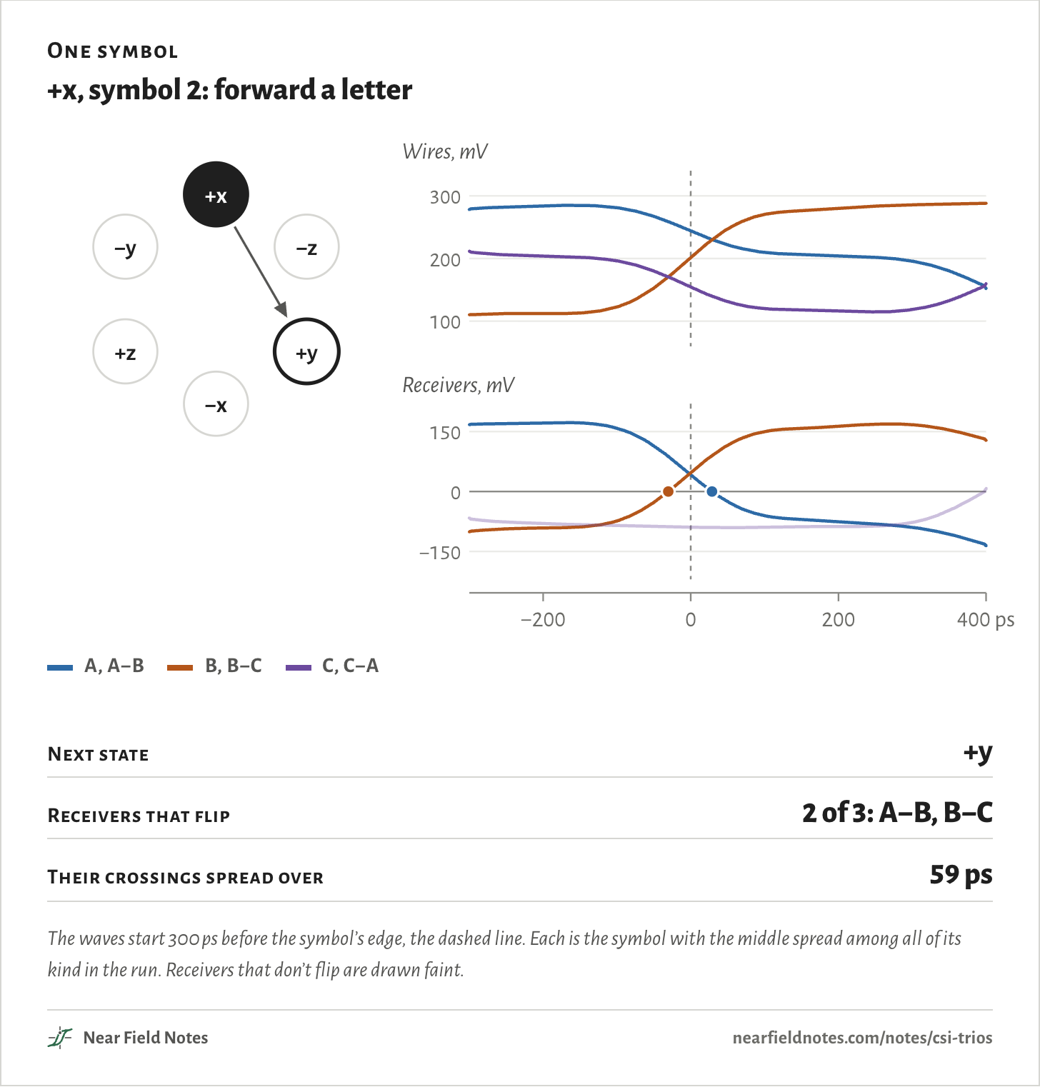
Pick a state and a symbol. The ring shows the move, and the waves are that move taken from the simulated run, with a dot where each receiver crosses zero.

From
Symbol
One symbol

+x, symbol 2: forward a letter

+x−z+y−x+z−y100200300Wires, mV−1500150Receivers, mV−2000200400 ps+x+z+x−z+x+y+x−y+x−x−x−z−x+z−x−y−x+y−x+x+y+x+y−x+y+z+y−z+y−y−y−x−y+x−y−z−y+z−y+y+z+y+z−y+z+x+z−x+z−z−z−y−z+y−z−x−z+x−z+z+x−z+y−x+z−y100200300Wires, mV−1500150Receivers, mV−2000200400 ps+x+z+x−z+x+y+x−y+x−x−x−z−x+z−x−y−x+y−x+x+y+x+y−x+y+z+y−z+y−y−y−x−y+x−y−z−y+z−y+y+z+y+z−y+z+x+z−x+z−z−z−y−z+y−z−x−z+x−z+z+x−z+y−x+z−y100200300Wires, mV−1500150Receivers, mV−2000200400 ps+x+z+x−z+x+y+x−y+x−x−x−z−x+z−x−y−x+y−x+x+y+x+y−x+y+z+y−z+y−y−y−x−y+x−y−z−y+z−y+y+z+y+z−y+z+x+z−x+z−z−z−y−z+y−z−x−z+x−z+z
  • A, A−B
  • B, B−C
  • C, C−A
Next state
+y
Receivers that flip
2 of 3: A−B, B−C
Their crossings spread over
59 ps
The waves start 300 ps before the symbol’s edge, the dashed line. Each is the symbol with the middle spread among all of its kind in the run. Receivers that don’t flip are drawn faint.
The numbers
Each drawing is the symbol with the middle spread among all of its kind in the 1,071-symbol run.
FromSymbolToReceivers that flipSpread, drawnSpread, all in the runTimes in the run
+x0+z261 ps56 ps to 70 ps38
+x1−z1——37
+x2+y259 ps54 ps to 68 ps37
+x3−y1——39
+x4−x38.9 ps1.1 ps to 16 ps18
−x0−z261 ps55 ps to 66 ps31
−x1+z1——36
−x2−y262 ps54 ps to 69 ps32
−x3+y1——44
−x4+x35.2 ps0.1 ps to 18 ps33
+y0+x261 ps53 ps to 68 ps34
+y1−x1——47
+y2+z260 ps56 ps to 69 ps35
+y3−z1——36
+y4−y35.9 ps0.0 ps to 17 ps25
−y0−x262 ps54 ps to 69 ps48
−y1+x1——26
−y2−z261 ps56 ps to 66 ps31
−y3+z1——37
−y4+y35.9 ps0.0 ps to 16 ps28
+z0+y260 ps55 ps to 67 ps34
+z1−y1——41
+z2+x262 ps55 ps to 68 ps43
+z3−x1——29
+z4−z35.5 ps0.0 ps to 19 ps32
−z0−y261 ps56 ps to 70 ps33
−z1+y1——33
−z2−x262 ps55 ps to 68 ps34
−z3+x1——33
−z4+z35.4 ps0.2 ps to 15 ps34

Conditions

Method
Circuit simulation in ngspice of one trio and one D-PHY lane, read by a model receiver. A 2D field solve of the trio’s cross-section. Renders in Blender.
Flex
15 cm of 50 Ω microstrip, 0.11 mm wide on 50 µm polyimide, effective permittivity 2.7, loss tangent 0.006, with skin loss: 1.7 dB at 1.25 GHz and 2.5 dB at 2.5 GHz.
Drivers
2.5 Gsym/s, edges half a symbol long, 0.4 V open circuit through 50 Ω, 1 pF on every pad at both ends. Trio levels 0, 0.2 and 0.4 V before the line.
Terminations
C-PHY: 50 Ω from each wire to one node with 10 pF to ground. D-PHY: 50 Ω from each wire to a center tap with 10 pF.
The run
1,071 symbols on each lane: seven 3s, the sync word, 0x7290 as 0224100, then 150 random words, all decoded. The spec’s table isn’t public, so the random words go through a base-5 stand-in. It changes which moves come up, not what each move looks like. The D-PHY lane carries random bits.
Receiver
The trio’s clock starts at the first crossing in each symbol, samples half a symbol later and ignores crossings for 0.6 of a symbol. The D-PHY lane is sampled mid-bit.
Opening figure
A second D-PHY run carries 0x7290’s 16 bits, most significant first, and a clock pair carries 1010. The clock is drawn half a symbol late, so its edges fall mid-bit.
Spectra
800 symbols each of a trio with random symbols, a pair with random bits and a clock pair, in 3.125 MHz bins. Common-mode current with one wire 5 ps late.
Cross-section
Fig. 29i and the tight and loose runs use a field-solved trio in place of the flex above: 96 µm traces 12 µm thick on 50 µm polyimide over a ground plane, under 25 µm of coverlay, effective permittivity 2.92. Tight is 0.5 widths apart and loose is 3.

The module and flex are drawn for the picture, not taken from a product.

Limits

  • The C-PHY and D-PHY specs are for MIPI members and weren’t read. Levels, terminations and layout rules here come from vendors’ documents and patents.
  • No equalization, no crosstalk between lanes and no package models.
  • The spectra are voltage at the receiver and common-mode current, not radiated field.
  • Which PHY a given phone wires up is rarely public.

Files

  • sim/cphy.pyWire states, moves, receivers and the stand-in mapping
  • sim/link.pyThe trio and the D-PHY lane on 15 cm of flex, and the eyes
  • sim/site.py0x7290 and the clock on a D-PHY lane
  • sim/trio3.pySpectra, skew, and tight against loose routing
  • sim/xsec3.pyThe cross-section’s field solve
  • render/module.pyThe module, flex and plug
  • refs/research_tech.mdHow C-PHY and D-PHY signal, with sources
  • refs/research_use.mdWhich sensors and processors use which
  • refs/research_routing_emi.mdLayout rules and emissions

Sources

Like this note?

Rev 1 ·
  1. Rev 1First published

Each fix gets a line here, with the reader's name if they want credit.

Did it answer your question?

Want more on this?

Report a problem

What should the next note be? Ask for one