Peltier coolers
Should you drive a Peltier cooler with PWM or steady DC?
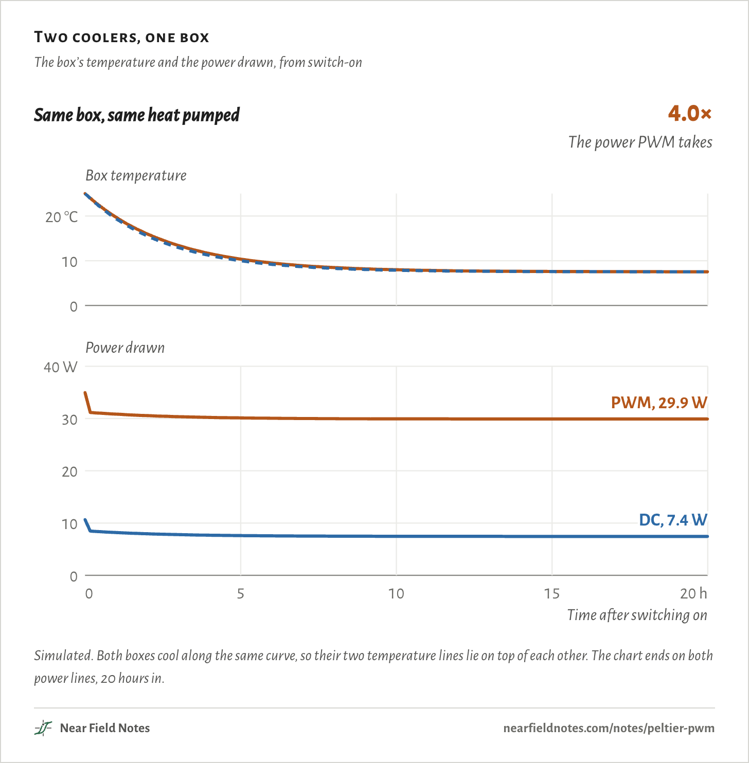
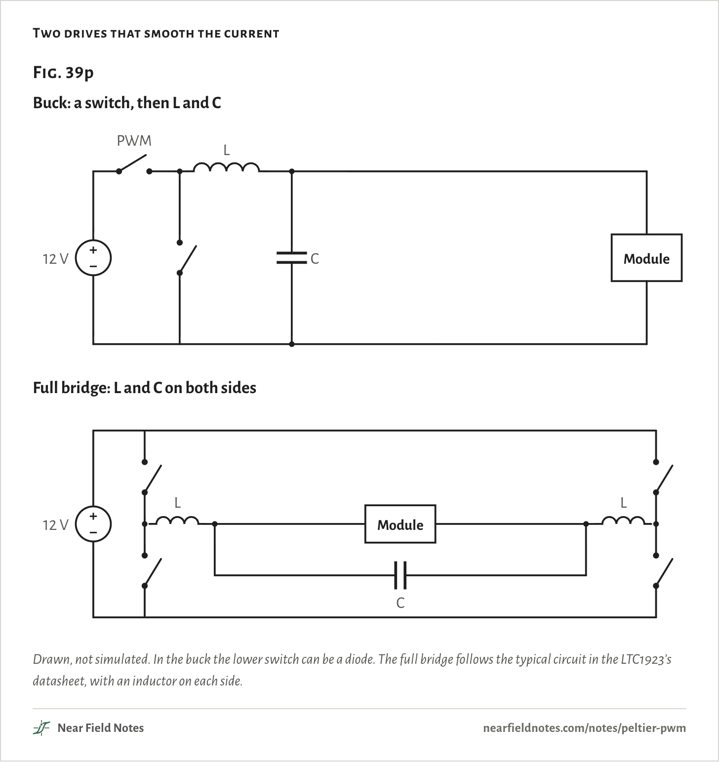
Steady DC. Simulated on a TEC1-12706 cooling a foam box from 12 V, unfiltered 50% PWM holds the box at 7.5 °C on 29.9 W. Steady DC at 4.68 V holds the same 7.5 °C on 7.4 W, a quarter of the power. A faster PWM doesn’t help. An inductor and a capacitor after the switch do.
The heat a module pumps follows its average current. Its resistive heat follows the square of the current, so PWM pays for its peaks.
A Peltier module is a DC motor with no inductance. A motor smooths PWM into steady current by itself. A module can’t.
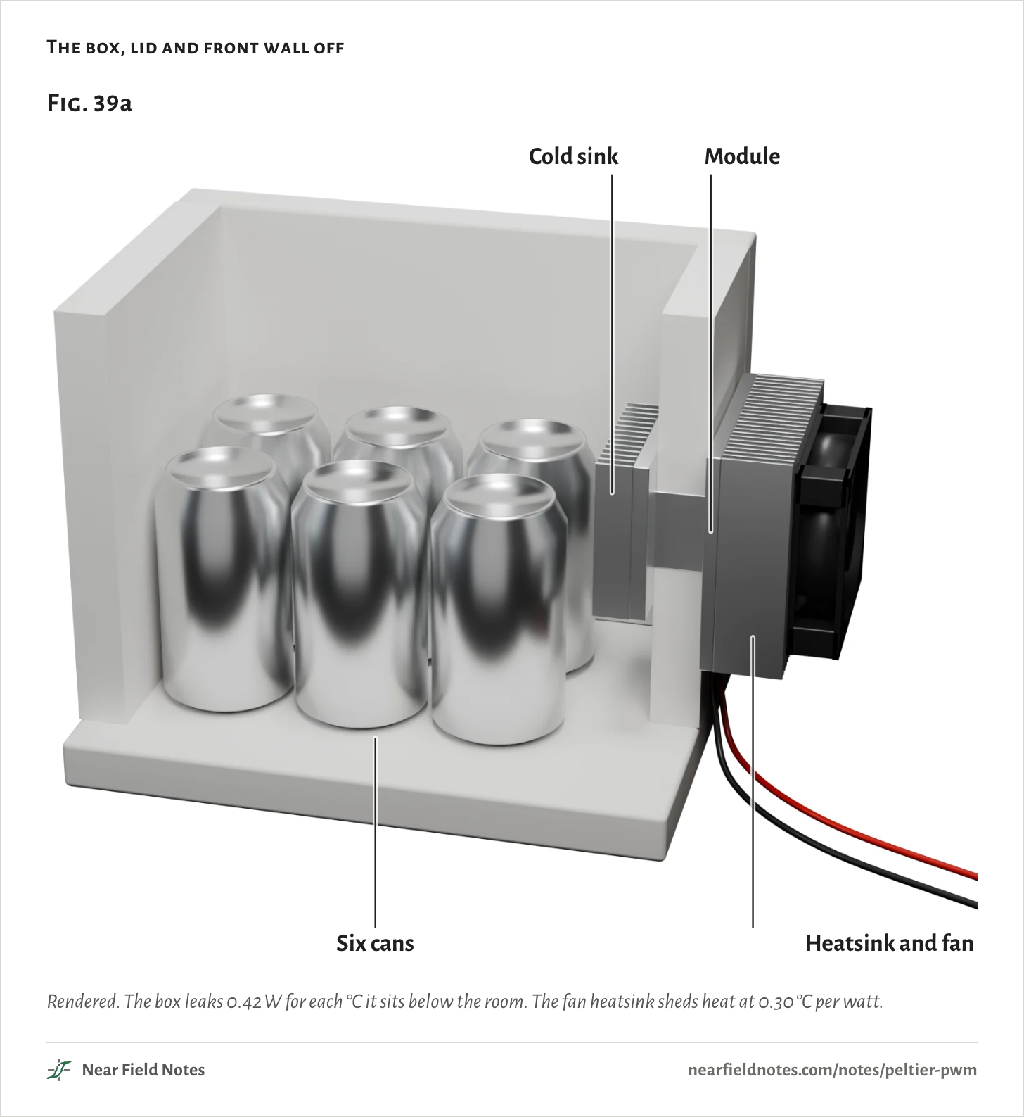
A foam box with a cooler in its wall
TEC1-12706, from 12 VTake a foam box of about 8 liters with six cans in it, in a 25 °C room. A cooler sits in one wall: a finned cold sink inside, an aluminum block through the foam, and a Peltier module, or thermoelectric cooler, against a fan heatsink outside.
The module is a TEC1-12706, the 40 mm, 12 V part sold almost everywhere. Thermonamic’s datasheet rates it at 6.1 A and 16 V.
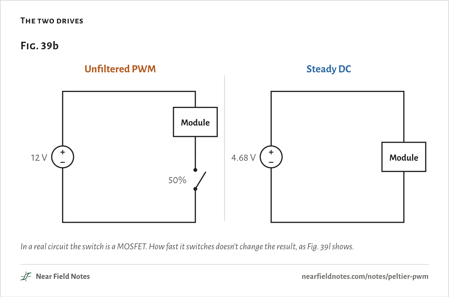
There are two ways to run it from 12 V. One is unfiltered PWM: a switch in series with the module, on for part of each cycle. It is the cheapest way to set the power.
The other is steady DC: a supply set to the voltage that holds the box at the same temperature. Here that is 4.68 V.
Inside the module
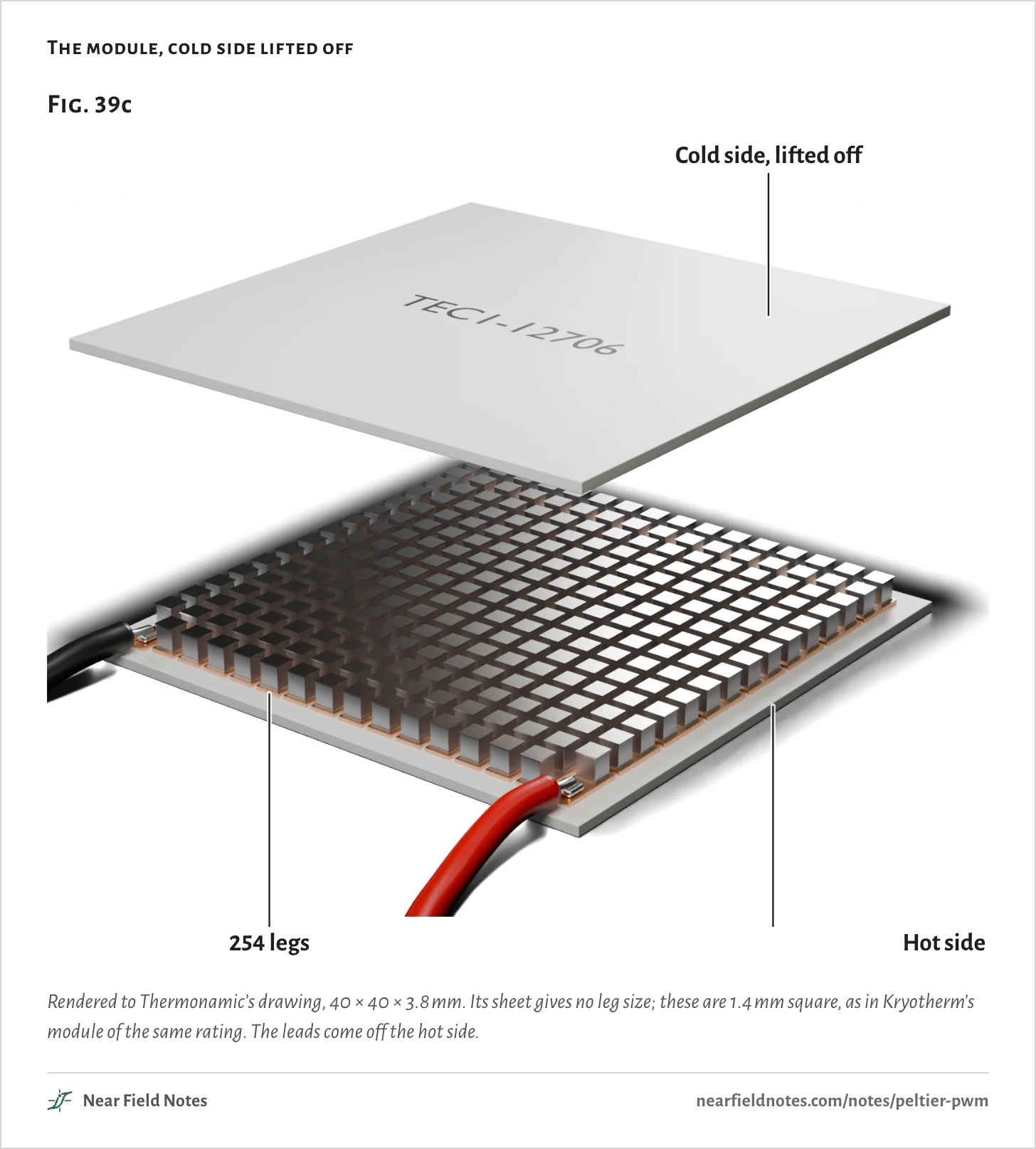
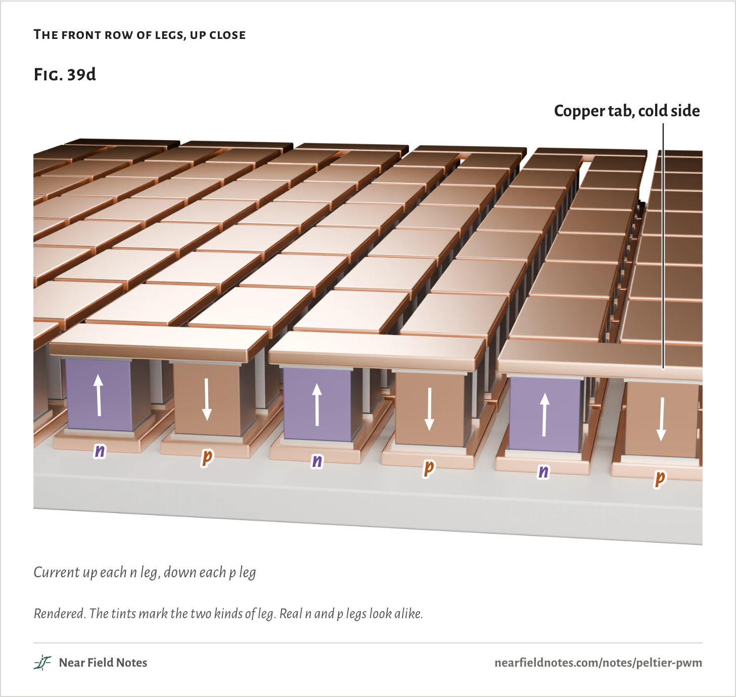
254 legs in seriesA Peltier module is 254 small legs of bismuth telluride between two thin squares of ceramic. Copper tabs on the ceramic join the legs in series, so one current runs through all of them.
Half the legs are n-type and half are p-type, and they alternate. The current runs up an n leg, across a tab and down the next p leg.
In an n leg the charge carriers are electrons, which move against the current. In a p leg they are holes, which move with it. So in every leg the carriers move the same way, from the cold side to the hot side.
They carry heat with them. That is the Peltier effect. In this module each amp carries about 15 W of heat, with the cold side at 5 °C.
Two taxes on every amp
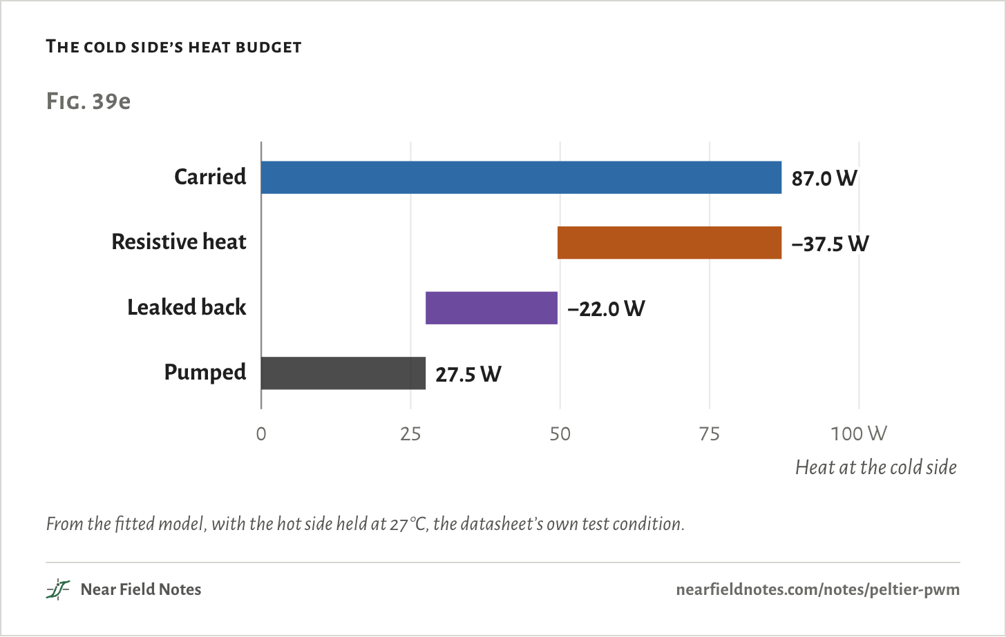
6.1 A, 40 °C across itThe legs have resistance, about 2 Ω in all. The current heats them, and half of that heat ends up at the cold side.
Heat also leaks back through the legs, from the hot side to the cold side, in step with the temperature across them.
At 6.1 A with 40 °C across it, the current carries 87.0 W. Resistive heat takes back 37.5 W and the leak 22.0 W, which leaves 27.5 W pumped.
The heatsink gets all of it: the 27.5 W pumped plus the 88.4 W the module draws at 14.5 V. That is 115.9 W to shed for 27.5 W of cooling.
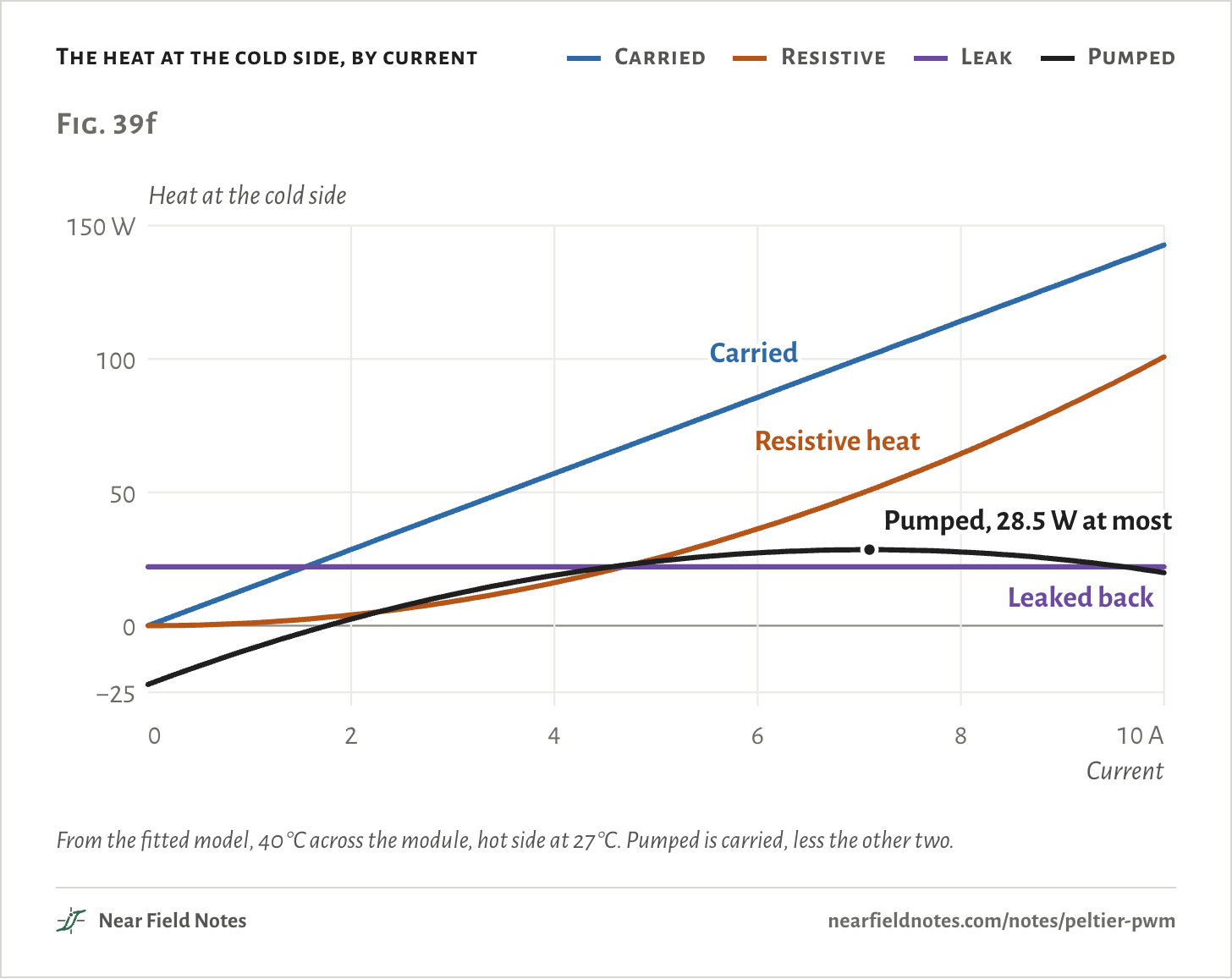
The heat carried grows with the current. The resistive heat grows with its square, so in the end it wins.
With 40 °C across it, this module pumps at most 28.5 W, at 7.1 A. With nothing to cool, its cold side gets coldest at 6.4 A: −43.5 °C. Push 10 A through it and the cold side only reaches −31.8 °C.
Read it like a DC motor
Temperature is speed, heat is torqueIf you know DC motors, you know this part. A motor’s voltage is its current times its resistance, plus a back-EMF that grows with its speed.
V = I·R + α·ΔT
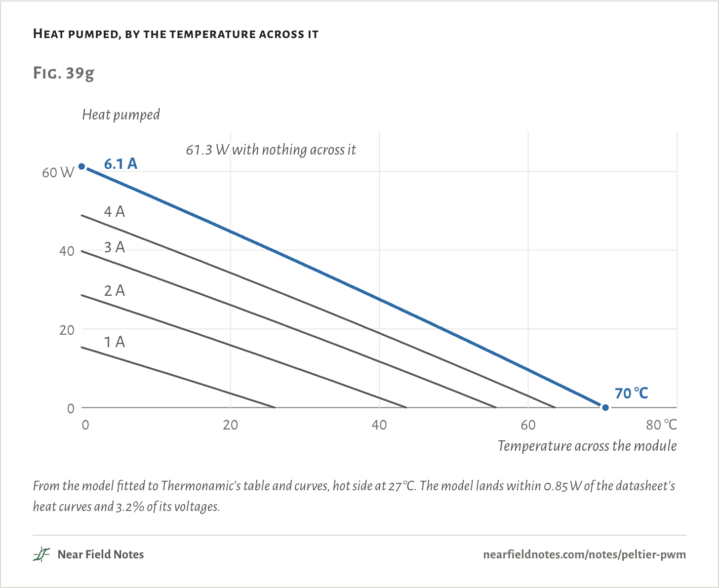
A module’s voltage is the same, with a back-EMF of about 55 mV for each °C across it. That is its Seebeck coefficient, α. So the temperature across a module plays the part of speed, and the heat it pumps plays torque. Note 40 runs the module backward, as a generator.
Stalled, with nothing across it, it pumps the most heat: 61.3 W, its Qmax. Running free, with nothing to cool, it holds the most temperature across it: 70 °C, its ΔTmax. Note 41 stacks modules to get past it.
At any one current, every load sits on the straight line between those two ends. The datasheet rates the module at the current that reaches ΔTmax and the voltage that takes, its Imax and Vmax.
The numbers
| Current | Pumped, 0 °C across | 20 °C across | 40 °C across | Zero at |
|---|---|---|---|---|
| 1 A | 15.3 W | 3.6 W | −8.8 W | 26 °C |
| 2 A | 28.6 W | 15.8 W | 2.5 W | 44 °C |
| 3 A | 39.7 W | 26.1 W | 11.7 W | 56 °C |
| 4 A | 48.9 W | 34.2 W | 18.9 W | 64 °C |
| 5 A | 55.9 W | 40.4 W | 24.1 W | 68 °C |
| 6.1 A | 61.3 W | 44.7 W | 27.5 W | 70 °C |
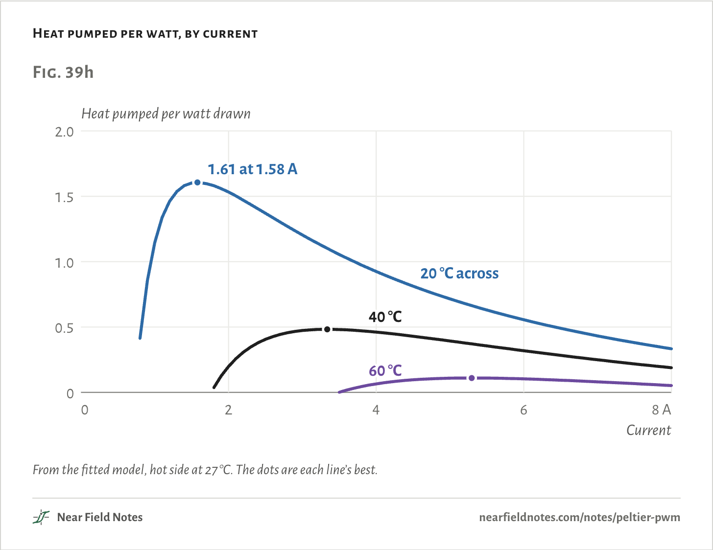
Like a motor, it works best lightly loaded. Its coefficient of performance, the heat pumped per watt drawn, peaks at 1.61 with 20 °C across it, at 1.58 A and 4.3 V. At 6.1 A it falls to 0.54.
With 40 °C across it the best is 0.48, at 3.3 A. Push more current and each extra watt buys less cooling.
The numbers
The best heat pumped per watt at each temperature difference, the model against the datasheet’s chart.
| Across the module | Best, model | Best, Thermonamic’s chart |
|---|---|---|
| 10 °C | 3.86 | 3.70 |
| 20 °C | 1.61 | 1.55 |
| 30 °C | 0.86 | 0.83 |
| 40 °C | 0.48 | 0.46 |
| 50 °C | 0.26 | 0.25 |
| 60 °C | 0.11 | 0.10 |
Unfiltered PWM into the module
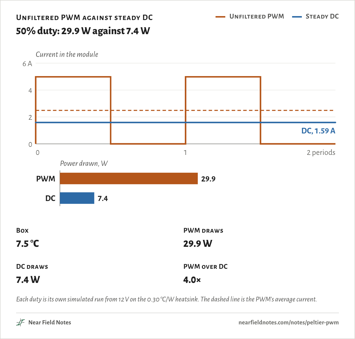
50% duty from 12 VNow the two coolers. At 50% duty the module gets the full 12 V half of the time: 4.98 A while on, nothing while off.
The heat it carries follows the average current, 2.49 A. Its resistive heat follows the square, so it heats like 3.52 A, the current’s rms. And while the switch is off, nothing pumps, but heat still leaks back.
The steady DC that holds the same box runs a flat 1.59 A.
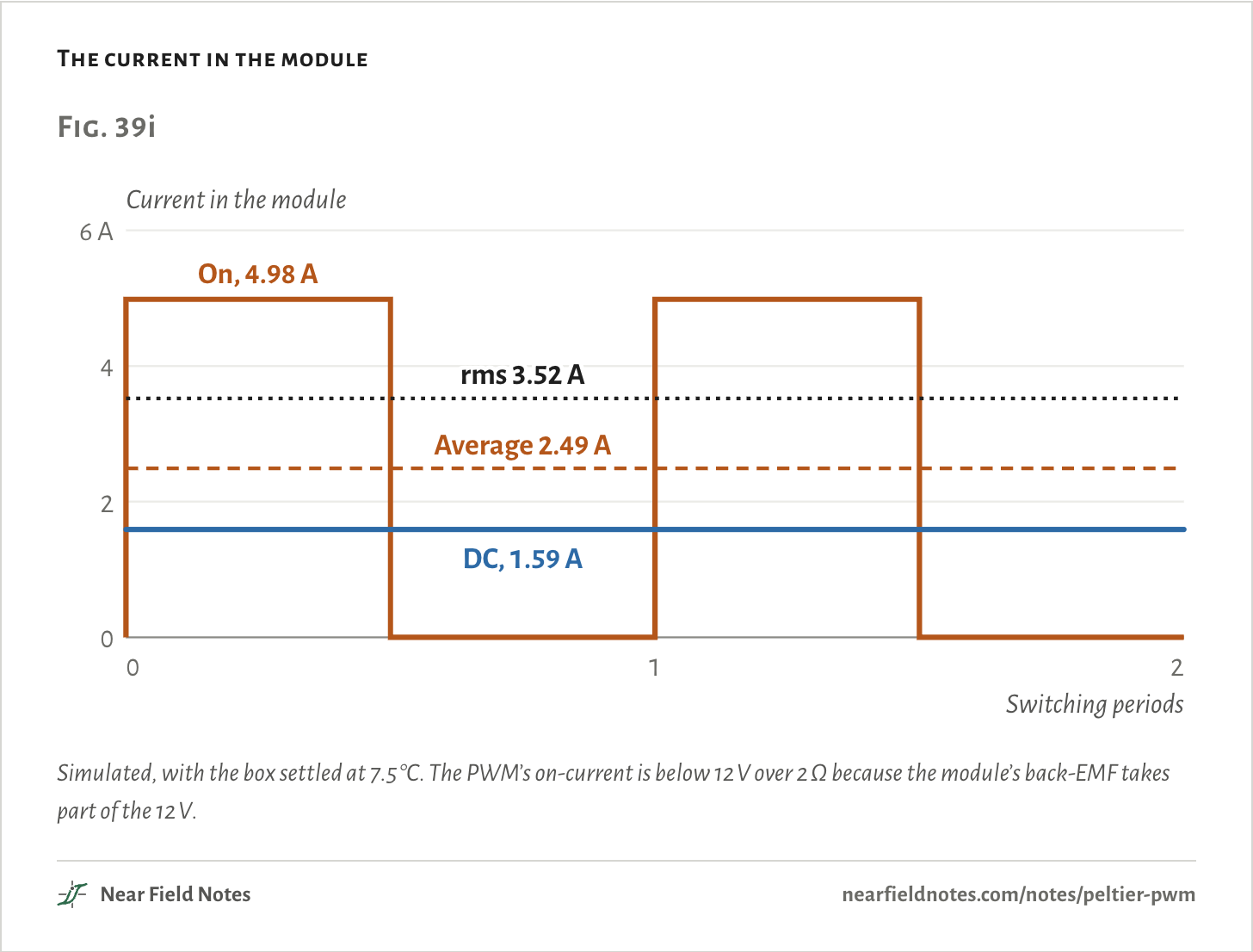
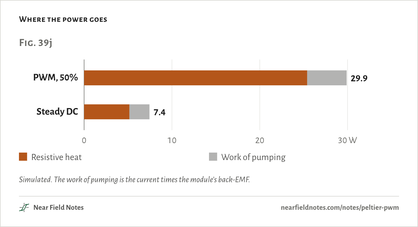
The box settles at 7.5 °C on 29.9 W. Steady DC holds the same 7.5 °C, pumping the same 7.3 W out of the box, on 7.4 W.
Nearly all the difference is resistive heat: 25.4 W on PWM against 5.2 W on DC. The work of pumping is small in both, 4.5 W against 2.3 W.
The heatsink pays for it too. It takes 37.2 W on PWM and 14.8 W on DC, and runs at 36.2 °C against 29.4 °C.
At every duty, DC wins
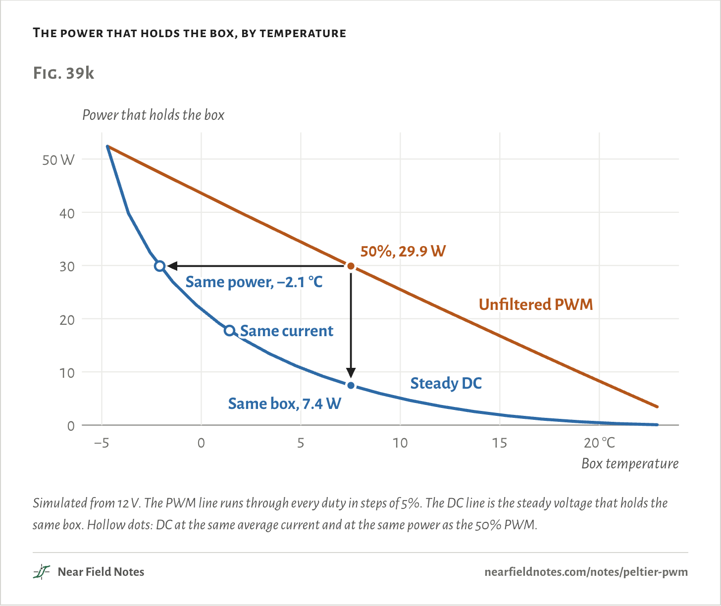
5% to 100%50% isn’t special. Every duty below 100% costs more than the DC that holds the same box.
At 25% PWM holds 15.4 °C on 16.1 W, where DC takes 1.8 W, 9 times less. At 75% it is 41.9 W against 19.1 W. The two meet at 100%, where PWM is just 12 V DC: −4.7 °C on 52.4 W.
Compare the 50% PWM with DC any other fair way and DC still wins. DC at the same average current cools the box to 1.4 °C on 17.8 W. DC at the same power cools it to −2.1 °C.
The numbers
| Duty | Box | PWM draws | PWM on | DC draws | DC at | PWM over DC |
|---|---|---|---|---|---|---|
| 5% | 22.9 °C | 3.4 W | 5.73 A | 0.07 W | 0.47 V | 48.9× |
| 10% | 20.9 °C | 6.8 W | 5.63 A | 0.28 W | 0.93 V | 24.1× |
| 15% | 19.0 °C | 10.0 W | 5.54 A | 0.63 W | 1.39 V | 15.8× |
| 20% | 17.1 °C | 13.1 W | 5.45 A | 1.1 W | 1.85 V | 11.6× |
| 25% | 15.4 °C | 16.1 W | 5.37 A | 1.8 W | 2.32 V | 9.1× |
| 30% | 13.7 °C | 19.0 W | 5.29 A | 2.6 W | 2.78 V | 7.4× |
| 35% | 12.1 °C | 21.9 W | 5.21 A | 3.5 W | 3.25 V | 6.2× |
| 40% | 10.5 °C | 24.6 W | 5.13 A | 4.6 W | 3.72 V | 5.3× |
| 45% | 9.0 °C | 27.3 W | 5.05 A | 5.9 W | 4.19 V | 4.6× |
| 50% | 7.5 °C | 29.9 W | 4.98 A | 7.4 W | 4.68 V | 4.0× |
| 55% | 6.1 °C | 32.4 W | 4.91 A | 9.2 W | 5.18 V | 3.5× |
| 60% | 4.7 °C | 34.9 W | 4.84 A | 11.2 W | 5.69 V | 3.1× |
| 65% | 3.4 °C | 37.3 W | 4.78 A | 13.4 W | 6.23 V | 2.8× |
| 70% | 2.2 °C | 39.6 W | 4.72 A | 16.0 W | 6.79 V | 2.5× |
| 75% | 0.9 °C | 41.9 W | 4.65 A | 19.1 W | 7.38 V | 2.2× |
| 80% | −0.3 °C | 44.1 W | 4.59 A | 22.6 W | 8.02 V | 1.9× |
| 85% | −1.4 °C | 46.3 W | 4.54 A | 27.0 W | 8.72 V | 1.7× |
| 90% | −2.6 °C | 48.4 W | 4.48 A | 32.4 W | 9.53 V | 1.5× |
| 95% | −3.7 °C | 50.4 W | 4.42 A | 39.8 W | 10.51 V | 1.3× |
| 100% | −4.7 °C | 52.4 W | 4.37 A | 52.4 W | 12.00 V | 1.0× |
A faster PWM doesn’t help
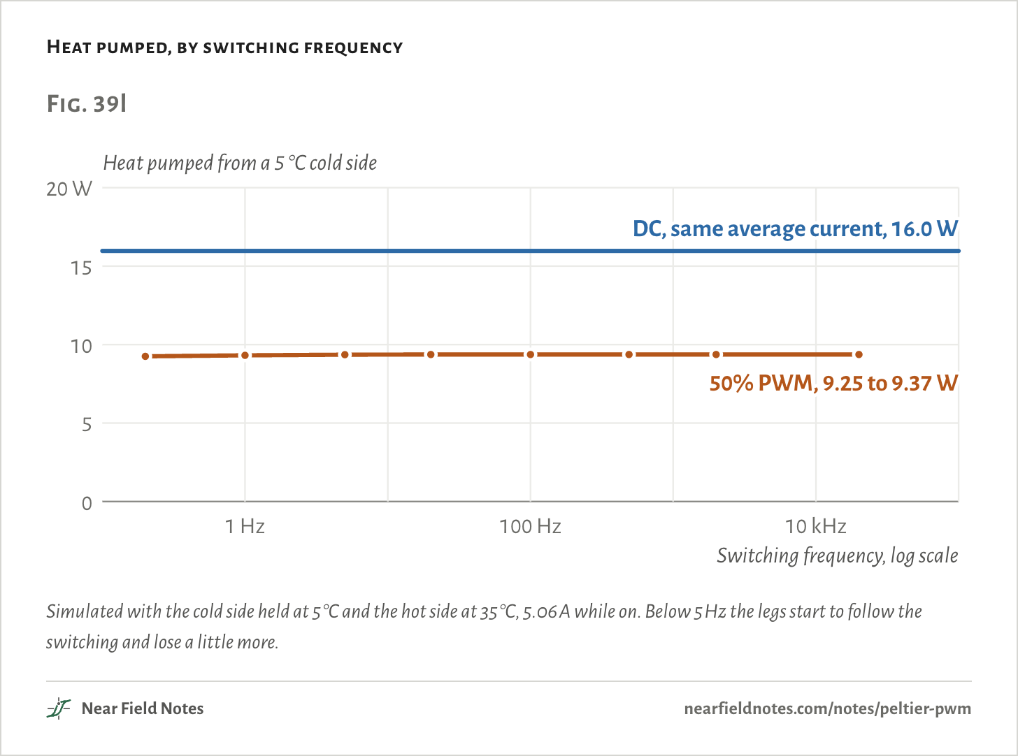
0.2 Hz to 20 kHzThe first thing to try is a higher PWM frequency. It doesn’t change the loss.
A model of the legs that lets their temperature rise and fall inside each cycle pumps 9.2 W at 0.2 Hz and 9.4 W at every frequency from 5 Hz to 20 kHz. DC at the same average current pumps 16.0 W.
Above a few hertz the legs can’t follow the switching. At 490 Hz, the PWM an Arduino Uno gives on most of its pins, their temperature swings 0.03 °C. The resistive heat is the same at every frequency, because it depends only on the rms current.
The numbers
| Frequency | Pumped | Drawn | Leg temperature swing |
|---|---|---|---|
| 0.2 Hz | 9.2 W | 30.6 W | 1.5 °C |
| 1 Hz | 9.3 W | 30.6 W | 1.4 °C |
| 5 Hz | 9.4 W | 30.5 W | 0.64 °C |
| 20 Hz | 9.4 W | 30.5 W | 0.32 °C |
| 100 Hz | 9.4 W | 30.5 W | 0.12 °C |
| 490 Hz | 9.4 W | 30.5 W | 0.031 °C |
| 2 kHz | 9.4 W | 30.5 W | 0.0076 °C |
| 20 kHz | 9.4 W | 30.5 W | 0.00076 °C |
| DC, same average | 16.0 W | 17.3 W | 0 |
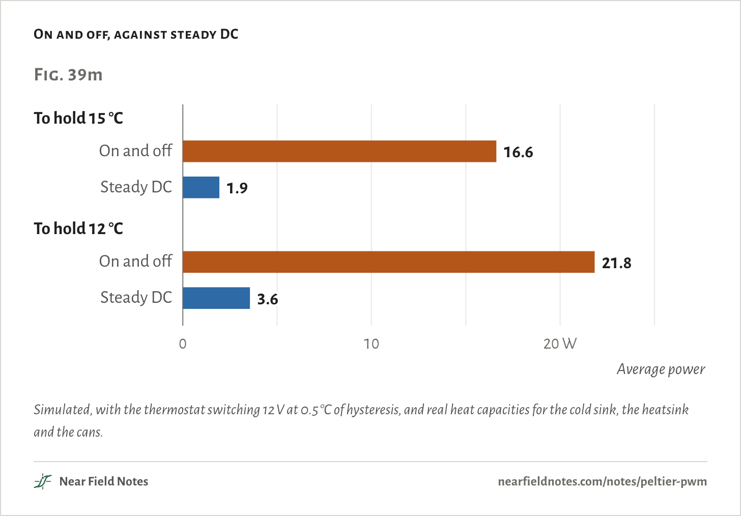
A thermostat that clicks the module fully on and off is the same thing, slower. Holding the box at 15 °C that way averages 16.6 W. Steady DC at 0.80 A holds it on 1.9 W.
Each cycle takes about 27 minutes, and the cold side swings 17.6 °C. Ferrotec says linear or proportional control should always be chosen over on and off when the module must last.
The numbers
| Held at | On and off | Time on | One cycle | Cold side swing | Steady DC | DC current |
|---|---|---|---|---|---|---|
| 15 °C | 16.6 W | 29% | 27 min | 17.6 °C | 1.9 W | 0.80 A |
| 12 °C | 21.8 W | 39% | 24 min | 17.3 °C | 3.6 W | 1.09 A |
Why a motor gets away with PWM
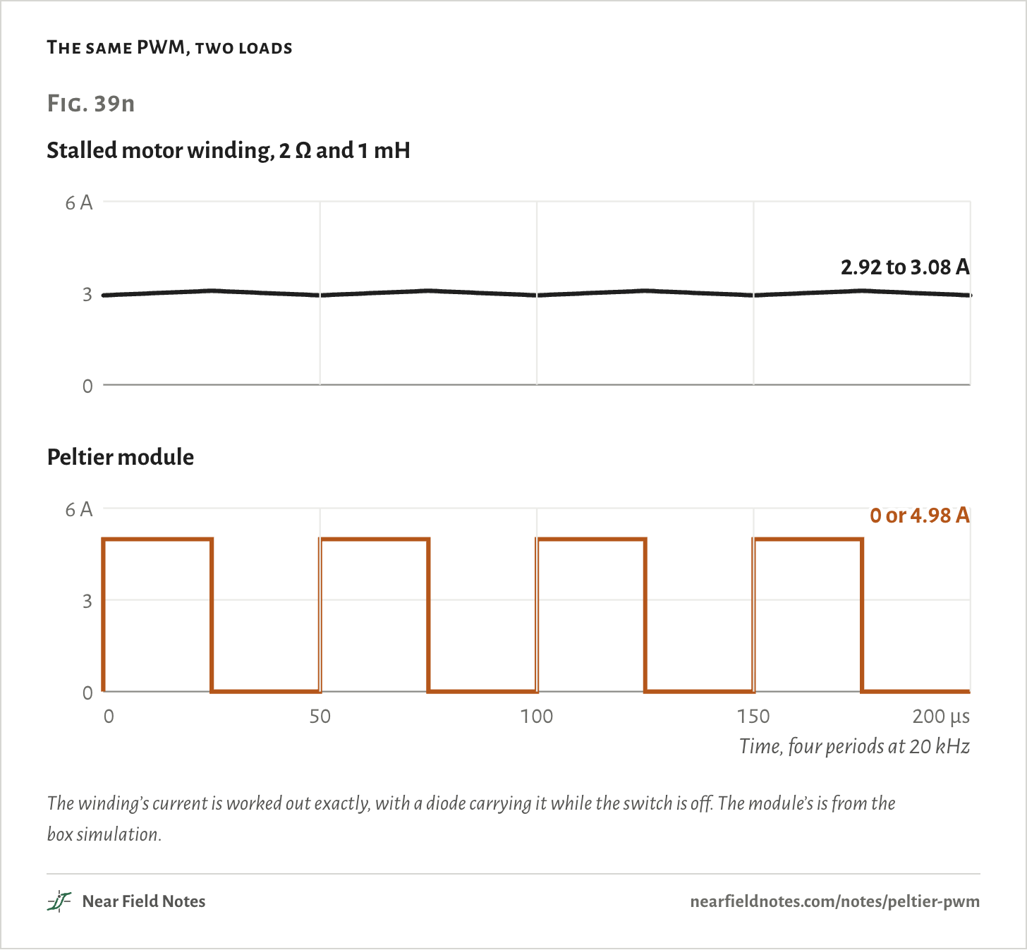
InductanceMotors run on PWM all the time. A winding’s inductance smooths the current, so the motor sees steady current with a little ripple on it.
On the same 12 V, 50%, 20 kHz PWM, a stalled winding of 2 Ω and 1 mH carries 2.92 A to 3.08 A. The module has next to no inductance, so it carries all or nothing.
Add the inductor
Ripple under 10%So give the module the inductance it lacks. An inductor and a capacitor after the switch make it a buck converter, and the module sees steady DC.
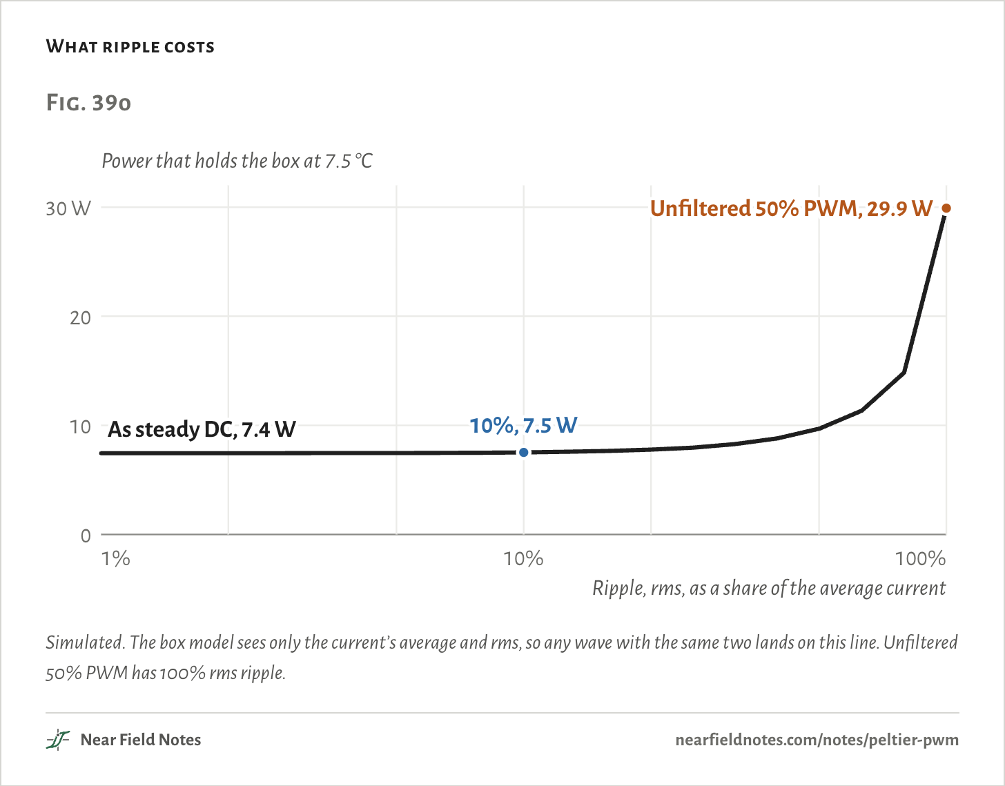
A little ripple costs little. Resistive heat goes with the square of the rms current, so 10% rms ripple adds 1%.
Holding the same box with 10% ripple takes 7.5 W, against 7.4 W on pure DC. With 20% it takes 7.8 W. TI and Laird both put the limit at 10% ripple, and ADI notes that module makers typically do too.
At 100 kHz an inductor of about 52 µH keeps the ripple in the inductor itself to 10%, before the capacitor takes most of what is left.
The numbers
| Ripple, rms | Power | More than DC |
|---|---|---|
| 0.0% | 7.4 W | 0.0% |
| 1.0% | 7.4 W | 0.0% |
| 3.2% | 7.5 W | 0.1% |
| 5.0% | 7.5 W | 0.3% |
| 10% | 7.5 W | 1.1% |
| 20% | 7.8 W | 4.3% |
| 32% | 8.3 W | 11.1% |
| 50% | 9.7 W | 30.3% |
| 79% | 14.8 W | 99.1% |
| 100% | 29.9 W | 301.5% |
Make it a full bridge and the current can run either way, so the same module heats or cools.
That is how a laser in a fiber-optic transceiver stays on its wavelength. Coherent’s cooled DWDM SFP+ holds its laser within ±100 pm of its channel and draws up to 1.9 W. Coherent’s uncooled 850 nm SFP+ draws under 1 W.
The chips made for the job filter their output hard. ADI’s ADN8834 datasheet says 1 µH and 10 µF at 2 MHz hold the worst-case voltage ripple across the module under 1%.
Set the duty yourself
5% to 100%Pick a duty. The chart shows the current in the module and the steady DC that holds the same box, and what each one draws.
- Box
- 7.5 °C
- PWM draws
- 29.9 W
- DC draws
- 7.4 W
- PWM over DC
- 4.0×
The numbers
| Duty | Box | PWM average | PWM rms | PWM draws | DC current | DC draws |
|---|---|---|---|---|---|---|
| 5% | 22.9 °C | 0.29 A | 1.28 A | 3.4 W | 0.15 A | 0.07 W |
| 10% | 20.9 °C | 0.56 A | 1.78 A | 6.8 W | 0.30 A | 0.28 W |
| 15% | 19.0 °C | 0.83 A | 2.15 A | 10.0 W | 0.45 A | 0.63 W |
| 20% | 17.1 °C | 1.09 A | 2.44 A | 13.1 W | 0.61 A | 1.1 W |
| 25% | 15.4 °C | 1.34 A | 2.68 A | 16.1 W | 0.76 A | 1.8 W |
| 30% | 13.7 °C | 1.59 A | 2.90 A | 19.0 W | 0.92 A | 2.6 W |
| 35% | 12.1 °C | 1.82 A | 3.08 A | 21.9 W | 1.08 A | 3.5 W |
| 40% | 10.5 °C | 2.05 A | 3.24 A | 24.6 W | 1.25 A | 4.6 W |
| 45% | 9.0 °C | 2.27 A | 3.39 A | 27.3 W | 1.42 A | 5.9 W |
| 50% | 7.5 °C | 2.49 A | 3.52 A | 29.9 W | 1.59 A | 7.4 W |
| 55% | 6.1 °C | 2.70 A | 3.64 A | 32.4 W | 1.77 A | 9.2 W |
| 60% | 4.7 °C | 2.91 A | 3.75 A | 34.9 W | 1.96 A | 11.2 W |
| 65% | 3.4 °C | 3.11 A | 3.85 A | 37.3 W | 2.15 A | 13.4 W |
| 70% | 2.2 °C | 3.30 A | 3.94 A | 39.6 W | 2.36 A | 16.0 W |
| 75% | 0.9 °C | 3.49 A | 4.03 A | 41.9 W | 2.58 A | 19.1 W |
| 80% | −0.3 °C | 3.67 A | 4.11 A | 44.1 W | 2.82 A | 22.6 W |
| 85% | −1.4 °C | 3.85 A | 4.18 A | 46.3 W | 3.09 A | 27.0 W |
| 90% | −2.6 °C | 4.03 A | 4.25 A | 48.4 W | 3.40 A | 32.4 W |
| 95% | −3.7 °C | 4.20 A | 4.31 A | 50.4 W | 3.79 A | 39.8 W |
| 100% | −4.7 °C | 4.37 A | 4.37 A | 52.4 W | 4.37 A | 52.4 W |
A bigger or smaller heatsink
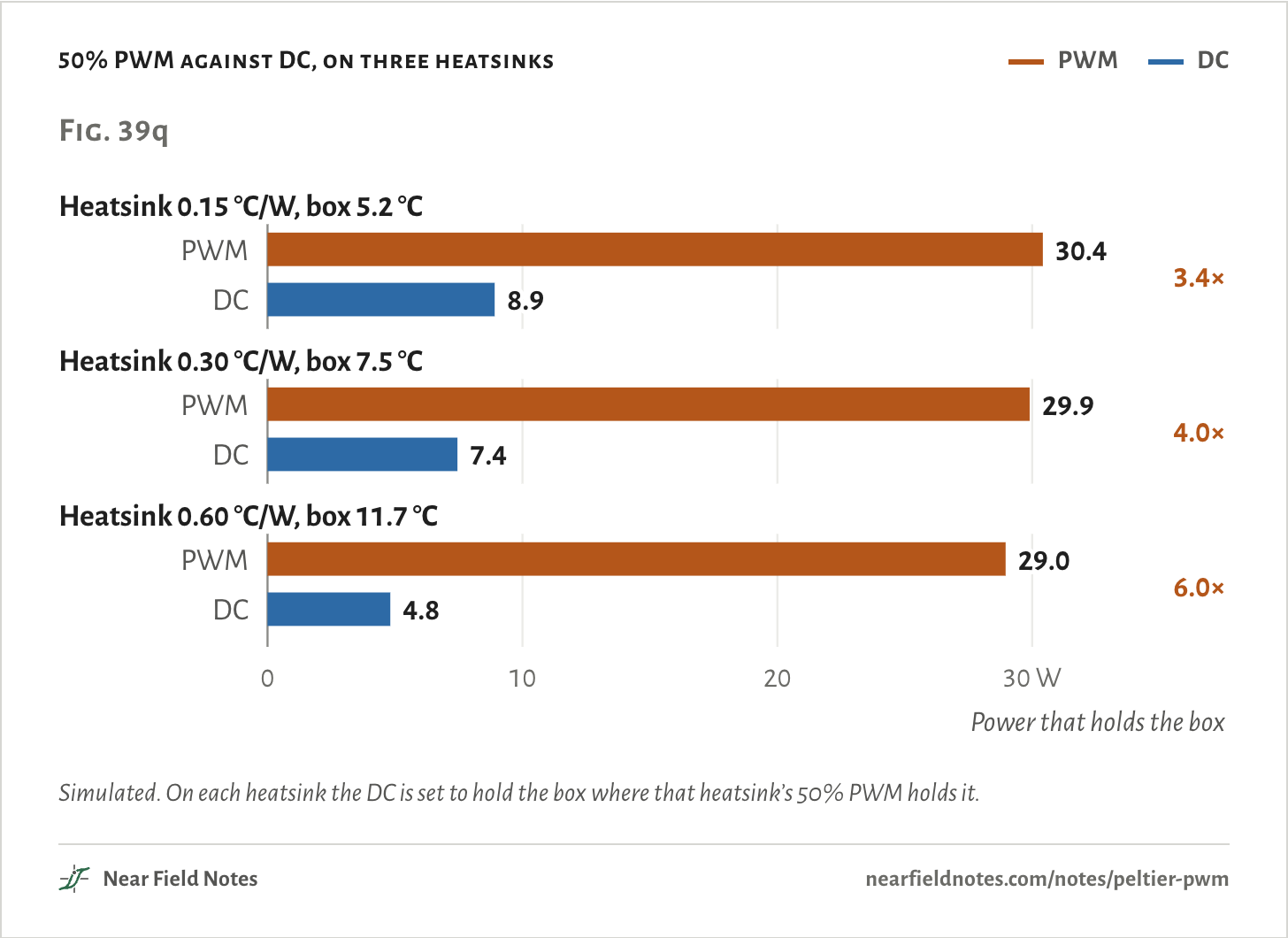
0.15 to 0.60 °C/WThe heatsink moves the box’s temperature, not the verdict.
On a heatsink twice as good, 50% PWM takes 30.4 W against 8.9 W for DC, 3.4 times as much. On one half as good it is 29.0 W against 4.8 W, 6.0 times.
How to drive one
Three questionsIt comes down to whether the module must also heat, and whether the supply can be set.
Key to driving a Peltier module
What goes between the supply and the module?
- 1aIt must heat as well as cool, as for a laser held at one temperatureFull bridge, L and C on both sides
- 1bIt only coolsGo to 2
- 2aThe supply’s voltage or current can be setSteady DC
- 2bIt runs from a fixed rail through a switchGo to 3
- 3aThe power or the heatsink’s size mattersL and C after the switch, ripple under 10%
- 3bNeither matters, as on a bench demoUnfiltered PWM works, at several times the power
The box in Fig. 39a ends at 2a or 3a. This page says nothing about the module’s life: TI ran one on PWM for five months, 3,600 hours, and saw no measurable change.
Conditions
- Simulated
- Every number on this page comes from a model fitted to the TEC1-12706’s datasheet. None was measured on a bench.
- Module
- Thermonamic TEC1-12706: 127 pairs of legs. Thermonamic gives no leg size. 1.4 × 1.4 × 1.5 mm is the size in Kryotherm’s TB-127-1,4-1,5, which has the same rating; it only sets how fast the legs follow the switching in Fig. 39l. The standard model of Lineykin and Ben-Yaakov, with the Seebeck coefficient, the resistance and the heat leak each a straight line in the module’s mean temperature. Its six numbers are fitted to the datasheet’s ratings at 27 and 50 °C and to 12 points on its curves. It gives 61.3 W, 70 °C, 6.4 A and 15.9 V, against the datasheet’s 61.4 W, 70 °C, 6.1 A and 16.0 V.
- Fixture
- Figs. 39e to 39h: the hot side held at 27 °C, the datasheet’s test condition.
- Box
- Room 25 °C. Fan heatsink 0.30 °C/W unless a figure says otherwise, cold sink 0.60 °C/W into the box’s air, and a foam box of about 8 liters with 25 mm walls that leaks 0.42 W per °C. 12 V supply. Settled values, except the opening figure’s 20 hours from switch-on. Fig. 39m adds heat capacities: cold sink 110 J/K, heatsink 380 J/K, six cans 8.5 kJ/K.
- PWM
- The box model sees only the current’s average, which pumps, and its rms, which heats. That holds at any frequency fast enough that the legs’ temperature can’t follow it. Fig. 39l checks it with a model of the legs in 1-D, cold side held at 5 °C and hot side at 35 °C.
- Motor
- Fig. 39n: a 2 Ω, 1 mH winding on 12 V, 50%, 20 kHz, with a freewheeling diode, worked out exactly in steady state.
- Render
- Blender, to Thermonamic’s drawing. The box is an example drawn for this page.
Fitted to a datasheet. Nothing on this page has been measured on a bench.
Limits
- The model misses the datasheet’s heat curves by up to 0.85 W and its voltages by up to 3.2%. TEC1-12706s from other makers differ from Thermonamic’s by more than that.
- Both drives are ideal: no loss in the switch, the wiring or a converter. A real buck loses a few percent in itself, far less than the gap between the two.
- The heatsink, the cold sink and the box each have one fixed figure. Real ones change a little with temperature, and a box gets opened.
- Below 5 Hz the box model and the model of the legs part ways, because the legs’ temperature starts to follow the switching. The box figures hold above that.
- The inductor for 10% ripple is worked out by hand, from the buck’s ripple formula. It wasn’t simulated.
- Nothing here models the module’s life. Ferrotec says over 200,000 hours between failures is not uncommon on steady DC, and its own test, 7.5 seconds on and 7.5 off, gave 125,000. TI saw no measurable change after 3,600 hours of PWM.
Files
- sim/tec.pyThe module model and its fit, the fixture, the box on PWM and on DC, ripple, the thermostat, and the legs in 1-D
- sim/site.pyEvery duty against DC, the power for each ripple, and the motor winding
- render/scene.pyThe module in Blender
- render/box.pyThe box and its cooler in Blender
Sources
- TEC1-12706 datasheet, Thermonamic’s sheet as re-badged by Conrad: ratings at 27 and 50 °C, the curves the model is fitted to, and the size
- The same Thermonamic datasheet under Thermonamic’s own header, as hosted by Dessy
- Kryotherm industrial TEC catalog, as hosted by AMS Technologies: TB-127-1,4-1,5, the TEC1-12706’s rating, with legs 1.4 × 1.4 mm and 1.5 mm tall
- S. Lineykin and S. Ben-Yaakov, “Modeling and Analysis of Thermoelectric Modules”, IEEE Transactions on Industry Applications 43(2), 505–512, 2007: the model
- TI SLUA979A, “Driving a Peltier Element (TEC): Efficiency and Aging”, 2020: constant current cooled 8.1 °C further than PWM at the same 1 A average, and five months, 3,600 hours, of PWM made no measurable change
- TI SLUA202A, a TEC controller with the UC3638: the LC filter, and “less than 10% ripple is recommended”
- TE Technology FAQ: “a ripple factor of 10% will only result in 1% degradation”
- Laird Thermal Systems, Thermoelectric Handbook, 2025: no more than 10% ripple, and the temperature lost to ripple
- RMT, application recommendations, archived June 2026: “the PWM method always results in TE module efficiency decrease”
- Meerstetter, TEC controller basics: “TEC modules driven by PWM are always less efficient”
- Ferrotec, thermoelectric reference guide, section 10: linear or proportional control over on and off, MTBFs over 200,000 hours on steady DC, and the on-and-off life test
- ADI ADN8834 datasheet: 1 µH, 10 µF and 2 MHz keep the worst-case voltage ripple across the module under 1%
- ADI LTC1923 datasheet: a full-bridge TEC controller whose typical circuit has a 10 µH inductor on each side of the module, and module makers’ 10% ripple limit
- Coherent FTLX3671MTCxx cooled DWDM SFP+ datasheet: ±100 pm of its channel and up to 1.9 W
- Coherent FTLX8574D3BCL SFP+ datasheet: an uncooled 850 nm laser, under 1 W
- Arduino analogWrite() reference, archived May 2024: 490 Hz on most PWM pins of an Uno
Like this note?
Rev 1 ·
- Rev 1First published
Each fix gets a line here, with the reader's name if they want credit.