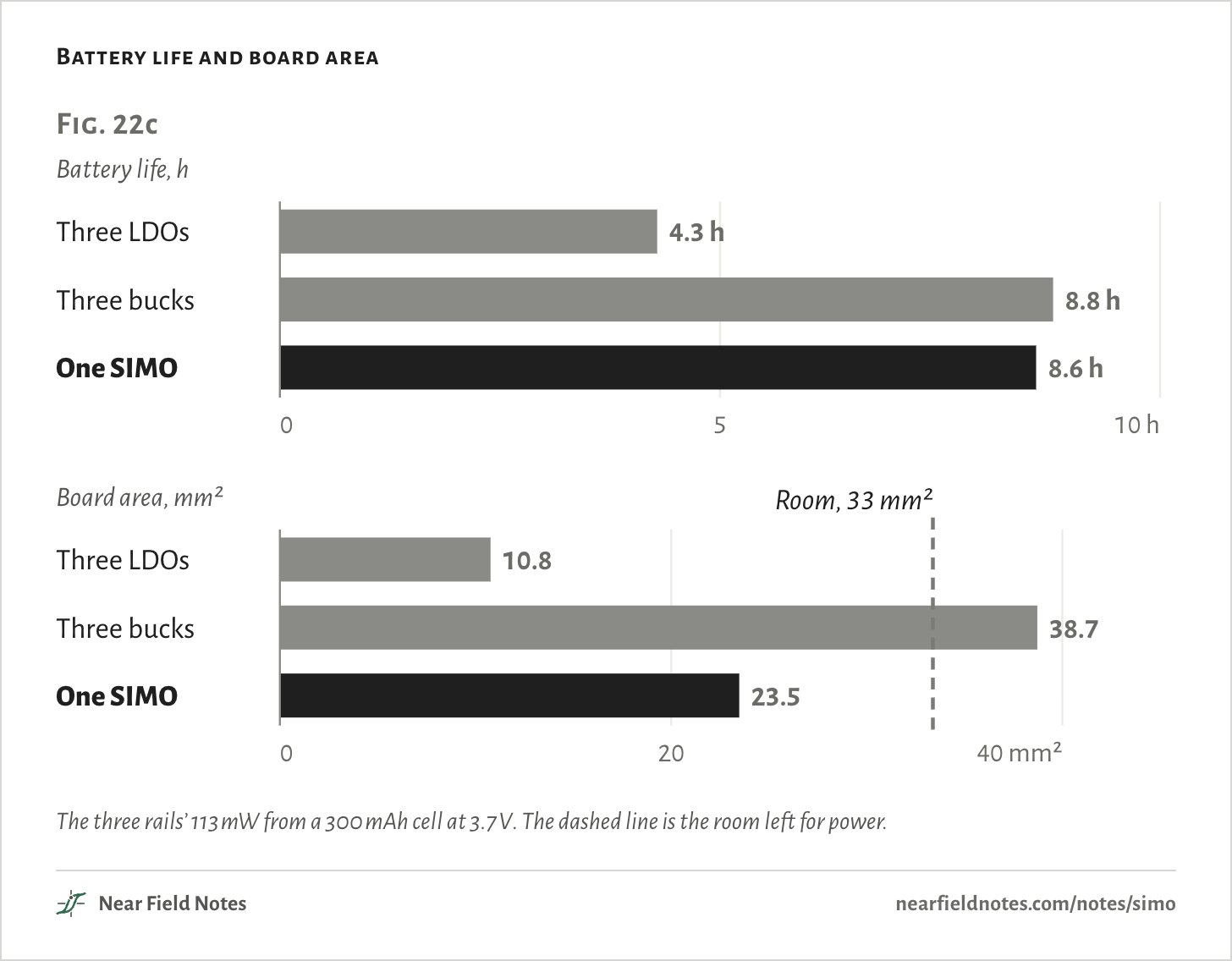
Yes, if the rails take turns. A single-inductor multiple-output converter, or SIMO, runs this watch’s three rails for 8.6 h, against 8.8 h from three bucks and 4.3 h from three LDOs. It takes 61% of the bucks’ board area.
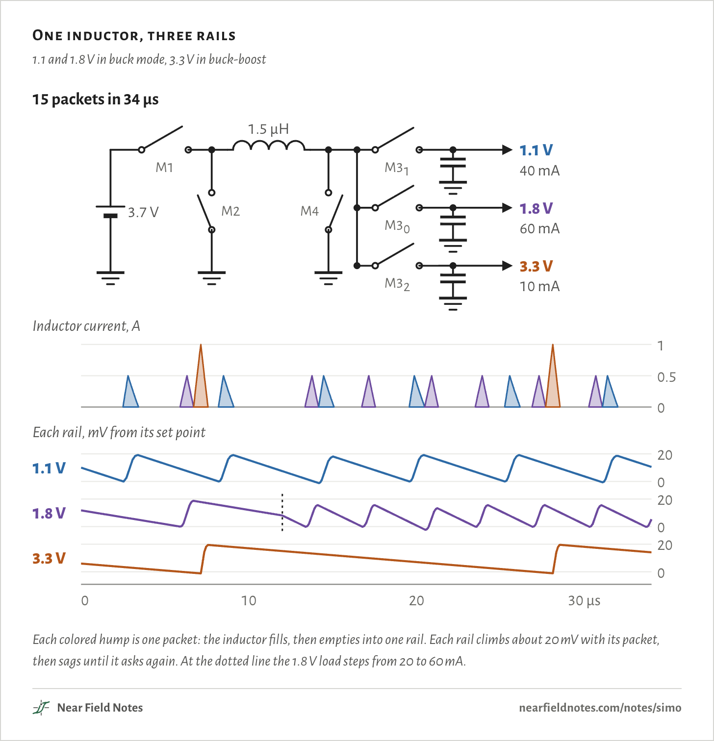
The figure is a model of the MAX77654 at work. Its one 1.5 µH inductor fills from the cell, then empties into whichever rail asks, one packet at a time.
One inductor, three rails
1.1 and 1.8 V in buck mode, 3.3 V in buck-boost
Each colored hump is one packet: the inductor fills, then empties into one rail. Each rail climbs about 20 mV with its packet, then sags until it asks again. At the dotted line the 1.8 V load steps from 20 to 60 mA.
Every packet
Packet
Rail
Mode
Starts
Peak current
Ends
1
1.1 V
buck mode
2.50 µs
0.5 A
3.42 µs
2
1.8 V
buck mode
5.90 µs
0.5 A
6.71 µs
3
3.3 V
buck-boost
6.71 µs
1.0 A
7.57 µs
4
1.1 V
buck mode
8.19 µs
0.5 A
9.11 µs
5
1.8 V
buck mode
13.35 µs
0.5 A
14.16 µs
6
1.1 V
buck mode
14.16 µs
0.5 A
15.08 µs
7
1.8 V
buck mode
16.73 µs
0.5 A
17.54 µs
8
1.1 V
buck mode
19.56 µs
0.5 A
20.48 µs
9
1.8 V
buck mode
20.48 µs
0.5 A
21.29 µs
10
1.8 V
buck mode
23.50 µs
0.5 A
24.31 µs
11
1.1 V
buck mode
25.25 µs
0.5 A
26.17 µs
12
1.8 V
buck mode
26.88 µs
0.5 A
27.69 µs
13
3.3 V
buck-boost
27.69 µs
1.0 A
28.55 µs
14
1.8 V
buck mode
30.27 µs
0.5 A
31.08 µs
15
1.1 V
buck mode
31.08 µs
0.5 A
32.00 µs
A crowded watch board
Three rails from one cell
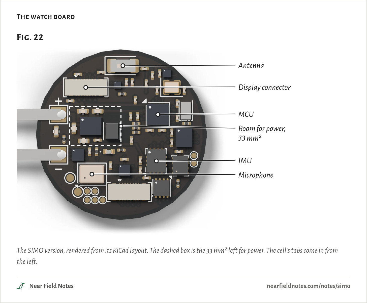
The board is a round watch board, 22 mm across and packed the way a watch’s is. An MCU, a chip antenna, the display’s connector, an IMU, a heart-rate sensor, a microphone and a fuel gauge leave 33 mm² for the parts that make the rails.
A 300 mAh lithium-ion cell at 3.7 V feeds three rails. The MCU’s core takes 40 mA at 1.1 V. Its I/O takes 20 mA at 1.8 V. The sensors take 10 mA at 3.3 V. That’s 113 mW in all.
The watch board
The SIMO version, rendered from its KiCad layout. The dashed box is the 33 mm² left for power. The cell’s tabs come in from the left.
The numbers
Part
Where, mm from top left
Antenna
11.2, 2.1
Display connector
6.4, 4.9
MCU
15.7, 8.4
IMU
15.5, 14.4
Microphone
7.2, 16.1
Room for power
4.30 to 10.95, 7.39 to 12.41. 33.4 mm²
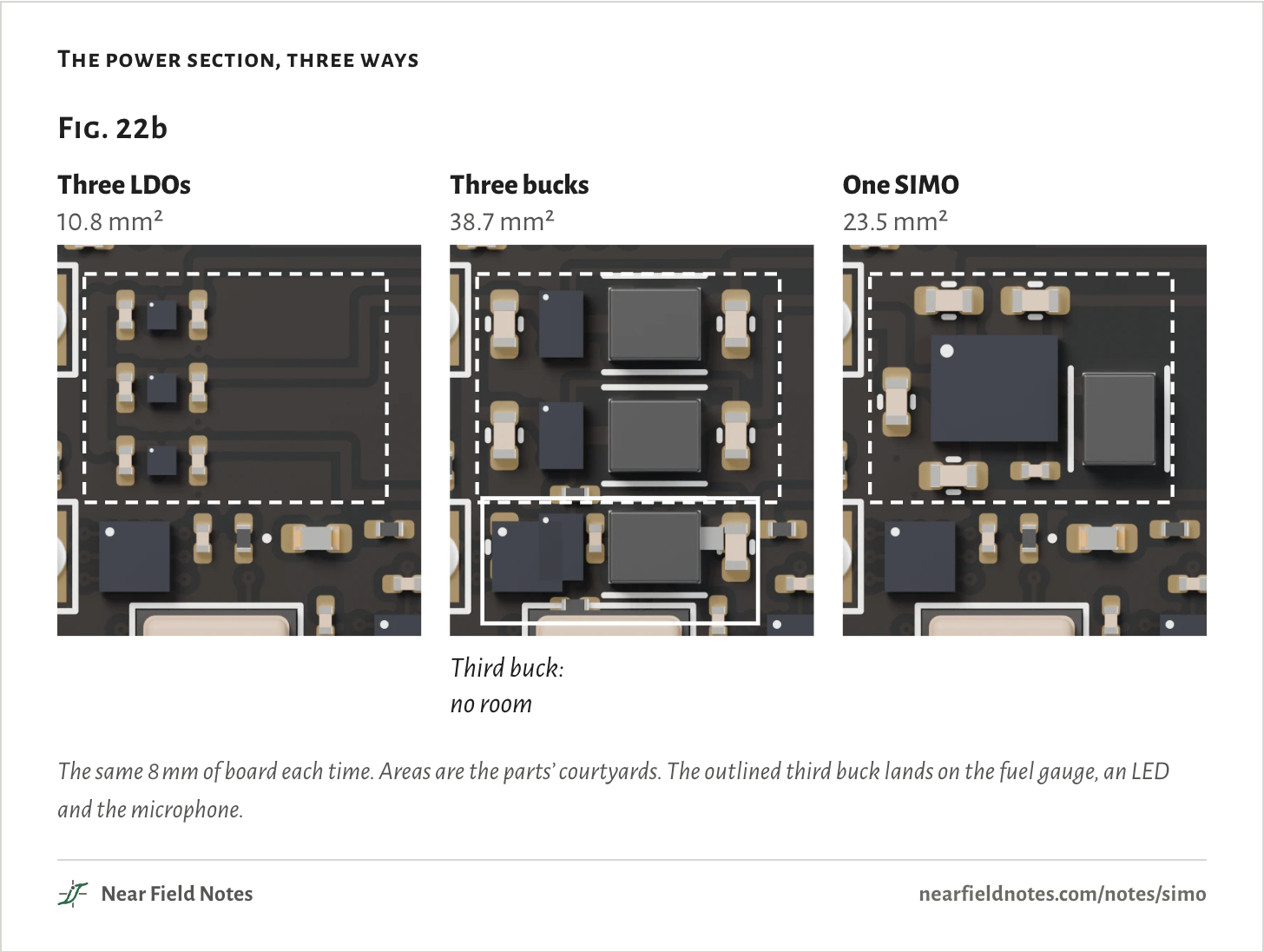
There are three usual ways to make the rails. An LDO is the smallest, a 0.64 mm chip with a capacitor each side. A buck needs an inductor of its own. A SIMO shares one inductor among all three rails.
At one scale, two bucks fill the room and the third has nowhere to go. The SIMO and its five capacitors fit.
The power section, three ways
The same 8 mm of board each time. Areas are the parts’ courtyards. The outlined third buck lands on the fuel gauge, an LED and the microphone.
An LDO passes its load’s current straight through from the cell. With three of them, battery life is the cell’s charge over the total current:
t=QI
=300 mAh70 mA=4.3 h
A buck or a SIMO converts power instead, and loses a little on the way. Its battery life is the cell’s energy over the power it draws:
t=Q·VcellPin
=300 mAh × 3.7 V129.2 mW=8.6 h
Here Pin is each rail’s power over its converter’s efficiency at that load, read off the datasheets’ curves, plus the SIMO’s own bias current.
The bucks and the SIMO both double the LDOs’ battery life. The bucks run 12 minutes longer.
The 3.3 V rail alone accounts for more than the whole gap. There the MAX77654’s curve gives 85%, against 93% for a TPS62840. On the other two rails the SIMO does a little better.
The SIMO trades those minutes for 15.2 mm² of board, room the bucks never had.
Battery life and board area
The three rails’ 113 mW from a 300 mAh cell at 3.7 V. The dashed line is the room left for power.
The numbers
Way
Battery power
Battery life
Board area
Three LDOs
259.0 mW
4.29 h
10.8 mm²
Three bucks
126.4 mW
8.79 h
38.7 mm²
One SIMO
129.2 mW
8.59 h
23.5 mm²
Heat, and no room
Why LDOs waste and bucks don’t fit
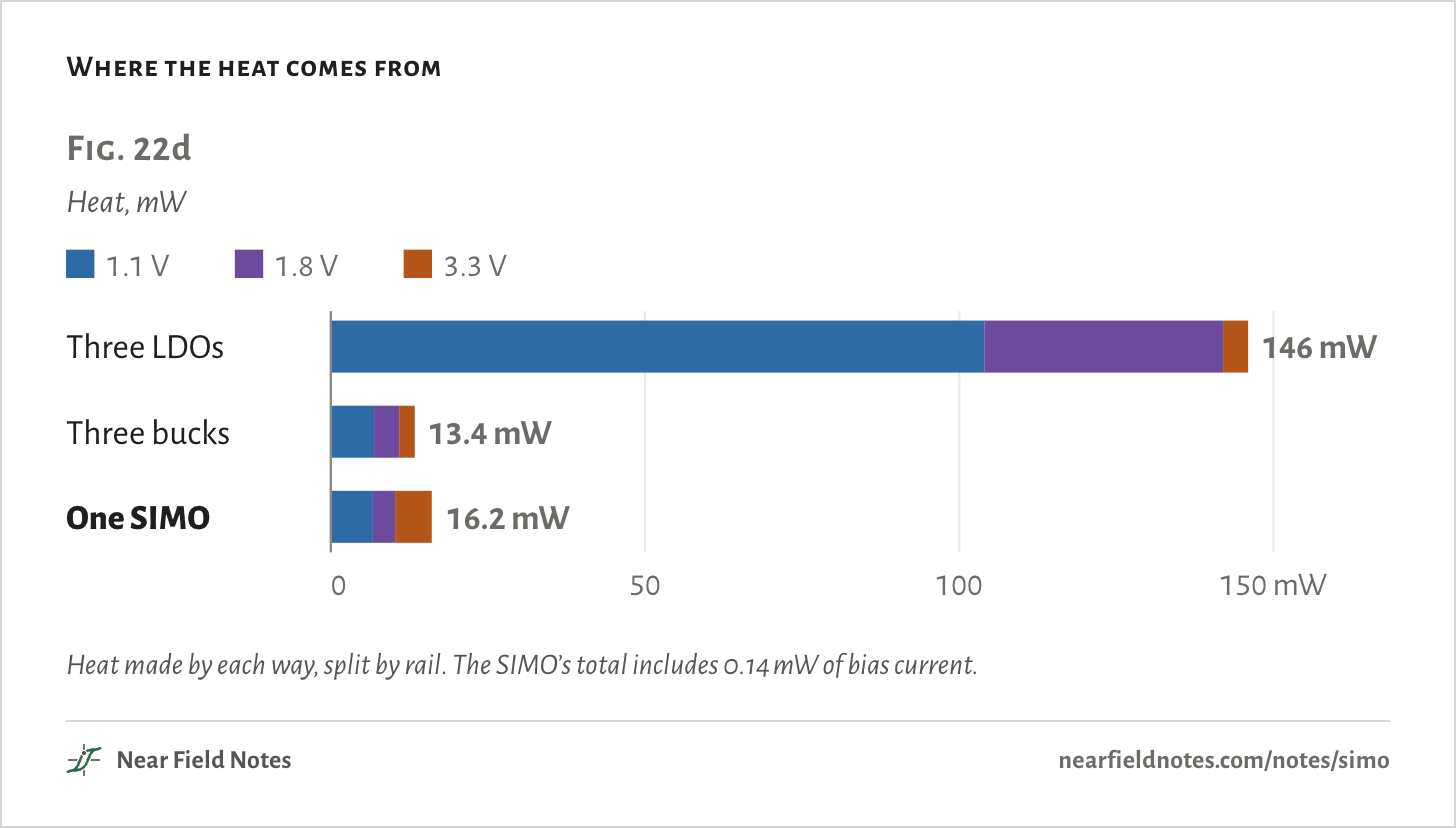
An LDO drops the difference between the cell and its rail across itself, and turns it into heat:
Pheat=(Vcell−Vout)·Iout
=(3.7 V − 1.1 V) × 40 mA=104 mW
The 1.1 V rail is the costly one. It delivers 44 mW and burns 104 mW doing it. The 3.3 V LDO sits close under the cell and loses only 4 mW.
Where the heat comes from
Heat made by each way, split by rail. The SIMO’s total includes 0.14 mW of bias current.
The numbers
Way
1.1 V rail
1.8 V rail
3.3 V rail
Quiescent
All
Three LDOs
104.0 mW
38.0 mW
4.0 mW
0.28 µW
146.0 mW
Three bucks
6.9 mW
4.0 mW
2.5 mW
0.67 µW
13.4 mW
One SIMO
6.7 mW
3.6 mW
5.8 mW
0.14 mW
16.2 mW
428
Low-dropout regulator
Tiny and simple, and it burns the difference
Field marks. A chip under a millimeter square with a capacitor each side, and no inductor. The TPS7A02 is 0.64 mm square.
Look-alike. A low quiescent current read as low loss. The TPS7A02’s 25 nA costs 0.09 µW here. The 2.6 V it drops at 40 mA costs 104 mW.
Range. Up to 200 mA, from 1.5 to 6 V in. Its efficiency is its output voltage over its input, so 30% for 1.1 V from 3.7 V.
Habitat. Wearables, meters, alarms and medical monitors, in TI’s list. Rails close under the cell, and loads of microamps.
429
Three bucks lose only 13.4 mW. But each needs a 2.0 by 1.6 mm inductor, and their parts’ courtyards add up to 38.7 mm², more than the 33 mm² room. In Fig. 22b the third buck lands on the fuel gauge, an LED and the microphone.
How a packet works
Fill, then empty
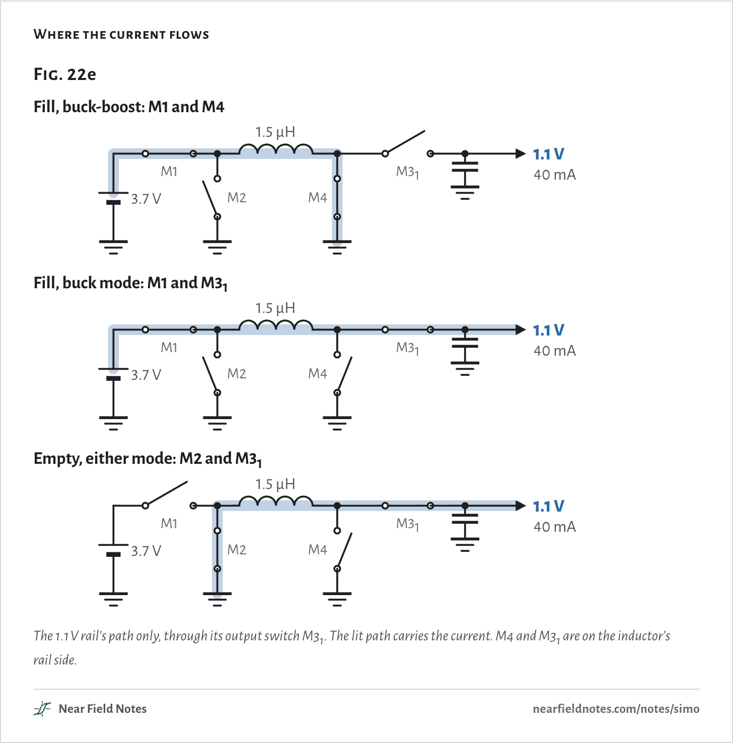
A SIMO has one inductor and a switch to each rail. Each time a rail asks, it gets one packet. The inductor fills to a set peak current, then empties into that rail until its current is back to zero. Then it rests until a rail asks again.
The MAX77654 can fill two ways. In buck-boost it fills to ground through M1 and M4, and the rail gets only the emptying half. In buck mode it fills straight into the rail through M1 and that rail’s output switch, M3x, as a plain buck does, and the rail gets both halves.
Buck mode needs the cell at least 0.7 V above the rail. That’s why the datasheet’s typical circuit runs 1.1 and 1.8 V in buck mode and 3.3 V in buck-boost, as the opening figure does. Buck-boost also keeps the 3.3 V rail up as the cell runs down below 3.3 V.
Where the current flows
The 1.1 V rail’s path only, through its output switch M31. The lit path carries the current. M4 and M31 are on the inductor’s rail side.
The numbers
Step
Closed
Current flows
The rail gets
Fill, buck-boost
M1, M4
Cell, inductor, ground
Nothing
Fill, buck mode
M1, M31
Cell, inductor, rail
The rising current
Empty, either mode
M2, M31
Ground, inductor, rail
The falling current
Rest
None
Nothing
Nothing
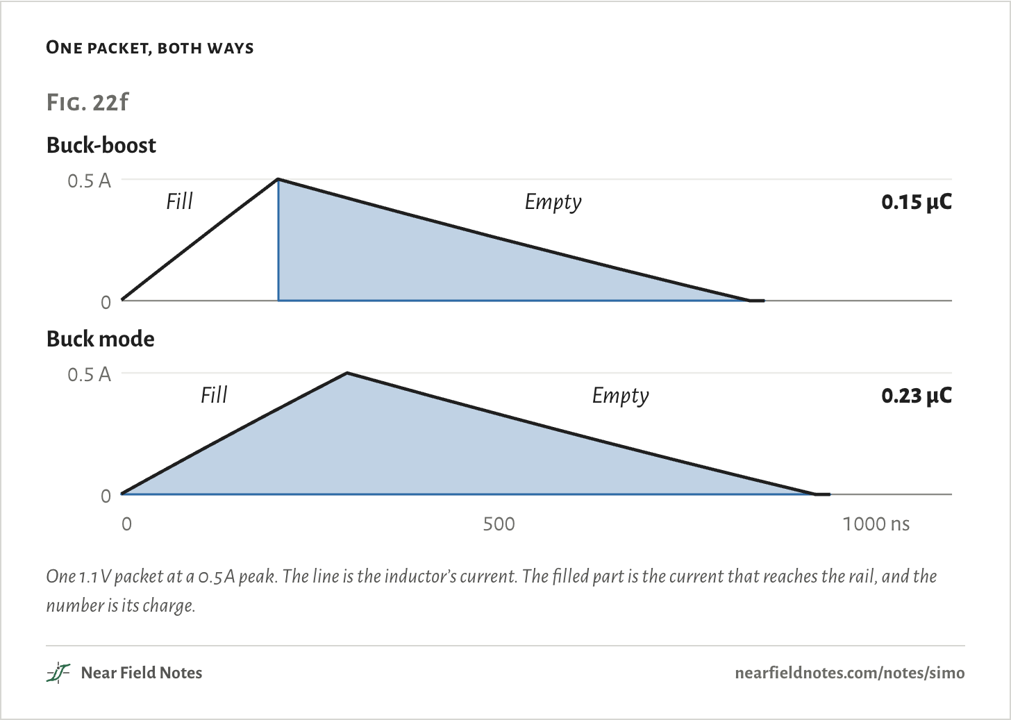
A buck-boost packet hands its rail the charge the inductor gives up as it empties:
qbb=L·Ipk22·Vout
=1.5 µH × (0.5 A)22 × 1.1 V=0.17 µC
In buck mode the fill adds its own share, more the closer the rail sits to the cell:
qbuck=qbb·VcellVcell−Vout
=0.17 µC ×3.7 V3.7 V − 1.1 V=0.24 µC
The sim gives 0.15 µC and 0.23 µC. Its switch and inductor resistance take a little off each packet.
One packet, both ways
One 1.1 V packet at a 0.5 A peak. The line is the inductor’s current. The filled part is the current that reaches the rail, and the number is its charge.
The numbers
Mode
Peak at
Ends at
Charge to 1.1 V
Lifts 10 µF by
Energy in
Energy out
buck-boost
208 ns
832 ns
0.152 µC
15.2 mV
196 nJ
168 nJ
buck mode
299 ns
920 ns
0.227 µC
22.7 mV
281 nJ
252 nJ
430
SIMO converter
One inductor, shared by taking turns
Field marks. One inductor beside a power chip with several switching outputs. On the MAX77654, a 3.3 nF capacitor from its BST pin to LXB as well.
Look-alike. One buck followed by LDOs, which also gets by with one inductor. The MAX77654’s datasheet compares itself with that, and claims better total system efficiency.
Range. Each output 0.8 to 5.5 V. Peak currents of 0.335, 0.5, 0.75 or 1 A. A 1.0 to 2.2 µH inductor, 1.5 µH for most designs. 1 µA of quiescent current per output.
Habitat. Hearables, fitness monitors, wearables and sensor nodes, in ADI’s list.
431
Taking turns
One rail at a time
Each rail has its own comparator, and asks when it falls to its set point. Rails that don’t ask are skipped. When none ask, the inductor rests.
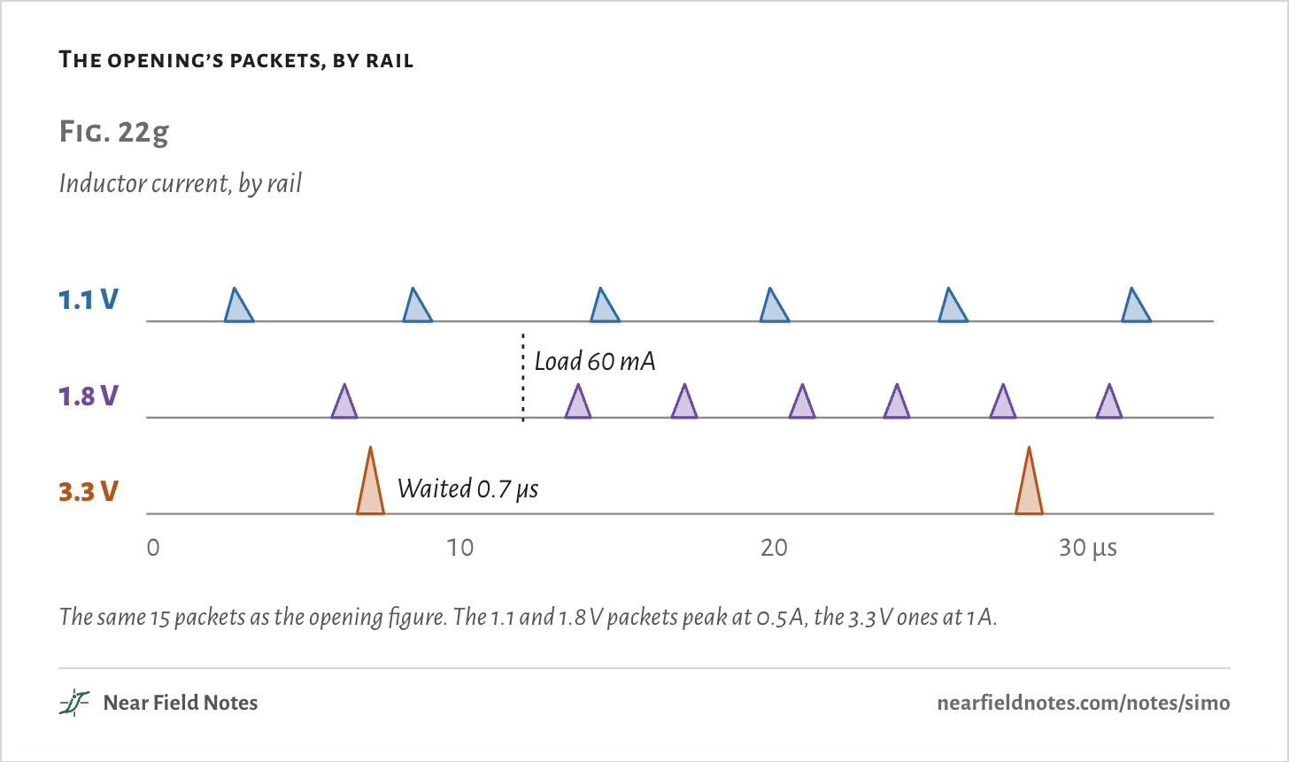
A rail that asks while the inductor is busy waits its turn. At 6 µs the 1.8 V rail asks and gets a packet. The 3.3 V rail asks 0.1 µs later and waits 0.7 µs for that packet to end. When several rails are waiting, they’re served in turn, starting after the rail served last.
A heavier load asks more often. After the 1.8 V load triples at 12 µs, that rail gets 6 packets in the next 22 µs. No rail falls more than 2.3 mV below its set point.
The opening’s packets, by rail
The same 15 packets as the opening figure. The 1.1 and 1.8 V packets peak at 0.5 A, the 3.3 V ones at 1 A.
The numbers
Rail
Packets before 12 µs
After
Lowest before
Lowest after
1.1 V
2
4
-0.05 mV
-0.61 mV
1.8 V
1
6
-0.02 mV
-2.34 mV
3.3 V
1
1
-1.14 mV
-1.06 mV
Ripple
What each packet lifts
Each packet lifts its rail by its charge over the rail’s capacitor. The datasheet sizes that capacitor from it, in its Eq. 3. Turned round, for buck-boost:
ΔV=L·Ipk22·Vout·C
=1.5 µH × (0.5 A)22 × 1.1 V × 10 µF=17.0 mV
One packet in the sim lifts the rail 15.2 mV, since resistance took some of its charge. In buck mode the fill’s charge adds to the lift. Either way, a bigger capacitor or a lower peak current makes it smaller.
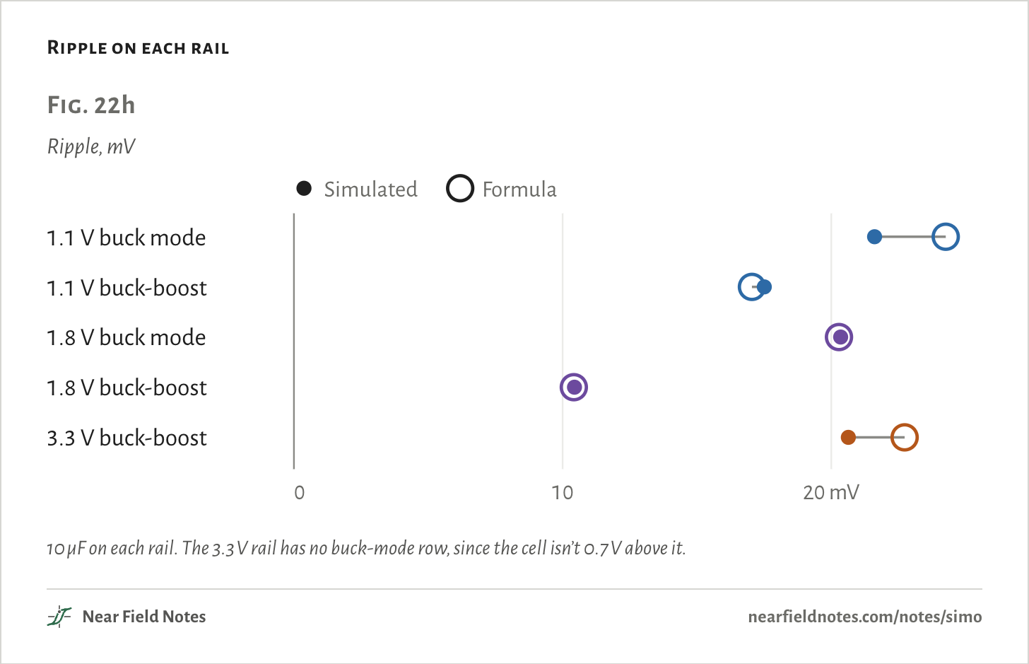
Fig. 22h sets the formula against the sim’s ripple, from each rail’s lowest point to its highest. They land within 3 mV on every rail. Resistance trims each packet, and the load keeps drawing while one is under way. A rail that has to wait sags further. In buck-boost the 1.1 V rail at one point waits behind two other packets and falls 5.5 mV below its set point. That puts its ripple above the formula.
The capacitors here are 10 µF. A 0402 ceramic gives less than that at its rail’s voltage, through DC bias, and the ripple grows to match. Note 13 compares the kinds.
Ripple on each rail
10 µF on each rail. The 3.3 V rail has no buck-mode row, since the cell isn’t 0.7 V above it.
The numbers
Rail
Mode
Formula
Simulated
Packets a second
1.1 V
buck mode
24.3 mV
21.6 mV
177,000
1.1 V
buck-boost
17.0 mV
17.5 mV
260,000
1.8 V
buck mode
20.3 mV
20.3 mV
100,000
1.8 V
buck-boost
10.4 mV
10.4 mV
207,000
3.3 V
buck-boost
22.7 mV
20.6 mV
47,000
What it costs
Busy time
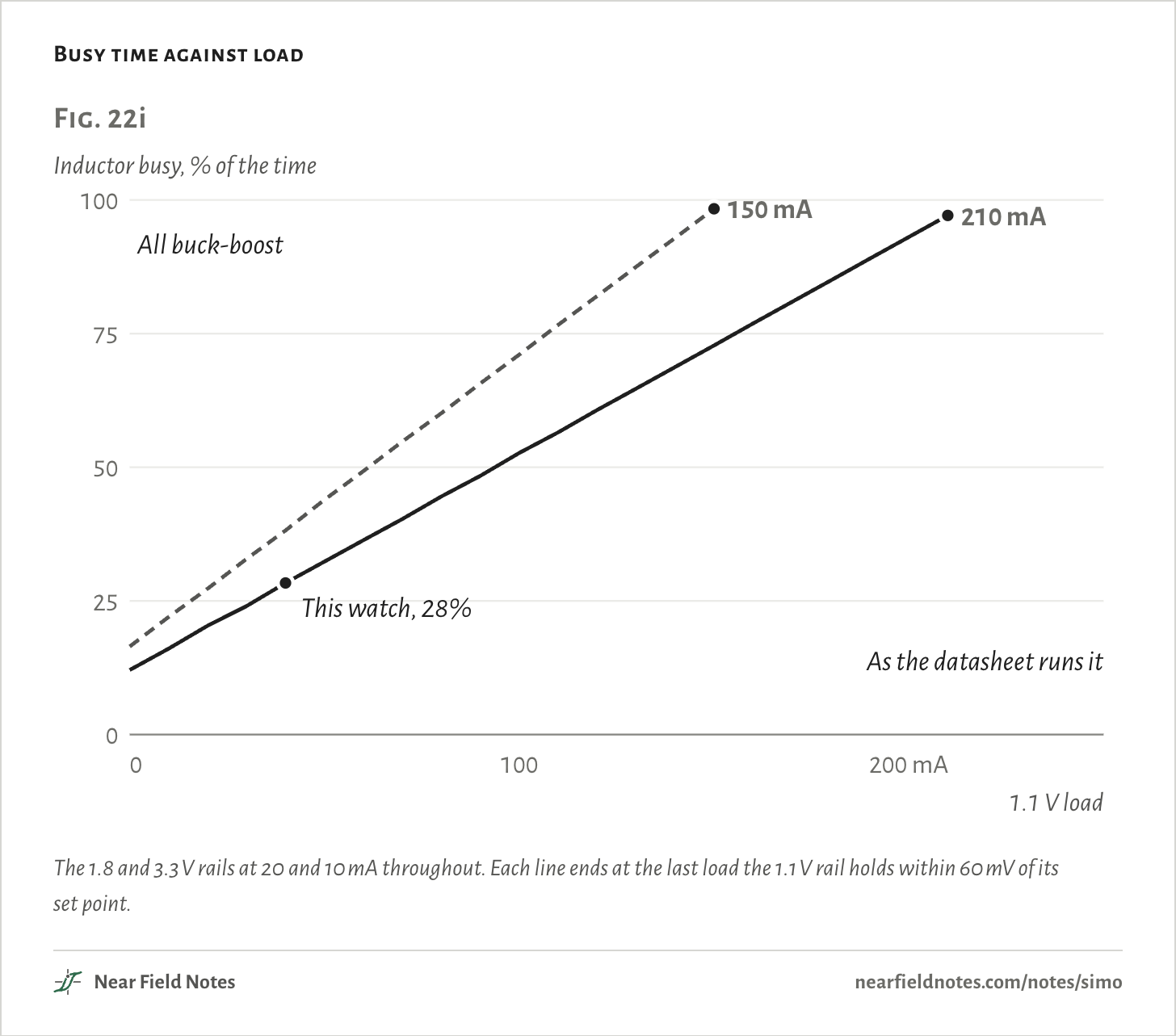
The rails share the inductor’s time. At this watch’s loads it’s busy 28% of the time. With every rail in buck-boost it would be busy 38%, since each packet then carries less.
Load the 1.1 V rail harder and its packets come closer together, until they run back to back. Run the datasheet’s way, it holds up to 210 mA. All buck-boost, it holds up to 150 mA. Past that it can’t keep up, and its voltage falls away.
Busy time against load
The 1.8 and 3.3 V rails at 20 and 10 mA throughout. Each line ends at the last load the 1.1 V rail holds within 60 mV of its set point.
Every load
1.1 V load
As the datasheet runs it
All buck-boost
0 mA
12%
16%
10 mA
16%
22%
20 mA
20%
27%
30 mA
24%
33%
40 mA
28%
38%
50 mA
32%
44%
60 mA
36%
49%
70 mA
40%
55%
80 mA
45%
60%
90 mA
48%
66%
100 mA
53%
71%
110 mA
57%
77%
120 mA
61%
82%
130 mA
65%
88%
140 mA
69%
93%
150 mA
73%
98%
160 mA
77%
can't keep up
170 mA
81%
can't keep up
180 mA
85%
can't keep up
190 mA
89%
can't keep up
200 mA
93%
can't keep up
210 mA
97%
can't keep up
220 mA
can't keep up
can't keep up
230 mA
can't keep up
can't keep up
240 mA
can't keep up
can't keep up
250 mA
can't keep up
can't keep up
432
Utilization
The share of time the inductor is busy
Field marks. Packets back to back with no rest between them, and one rail sagging under load while the others hold.
Look-alike. A buck’s duty cycle. That is one switch’s share of a fixed period. A SIMO has no fixed period, and its busy time counts every packet to every rail.
Range. 28% at this watch’s loads, and 97% at the most its 1.1 V rail holds. Over 100%, the datasheet says, the outputs droop.
Habitat. Every SIMO. The MAX77654’s design example works it out from each rail’s load, peak current and voltages, and keeps it under 80%.
433
The datasheet’s fix for too much busy time is a higher peak current. Each packet then carries more, so fewer are needed, but the ripple grows with the square of the peak current.
The switching frequency has no fixed value either. It follows the loads. In the sim, the 1.1 V rail at 210 mA takes 910,000 packets a second. The datasheet gives about 327 kHz for its own 3.7 to 1.2 V example, and as low as 10 Hz with no load.
Which way to make the rails
A key
Key to a small board’s rails
What should make three rails from one cell?
1aEvery rail sits close under the cell, or draws microampsLDOs
1bA rail sits far under the cell and draws milliampsGo to 2
2aThere’s room for an inductor on each railA buck for each
2bThere’s room for one inductorGo to 3
3aIts packets keep it busy under 80%One SIMO
3bThey’d keep it busy over 80%One SIMO, higher peak currents
This watch’s answer is 3a: its inductor is busy 28% of the time.
Load the rails yourself
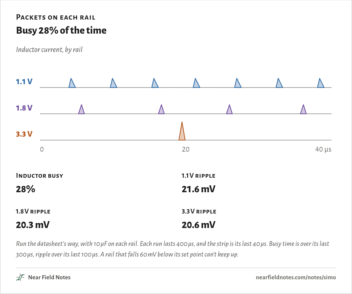
100 runs, every one drawn
Set each rail’s load. Each hump is one packet of inductor current to that rail.
A heavier load asks more often and takes more of the inductor’s time. Load the rails heavily and the inductor runs out of time. The 1.1 V rail falls behind first.
Packets on each rail
Busy 28% of the time
Inductor busy
28%
1.1 V ripple
21.6 mV
1.8 V ripple
20.3 mV
3.3 V ripple
20.6 mV
Run the datasheet’s way, with 10 µF on each rail. Each run lasts 400 µs, and the strip is its last 40 µs. Busy time is over its last 300 µs, ripple over its last 100 µs. A rail that falls 60 mV below its set point can’t keep up.
Every case, as a table
1.1 V load
1.8 V load
3.3 V load
Busy
1.1 V ripple
1.8 V ripple
3.3 V ripple
10 mA
5 mA
5 mA
8%
21.8 mV
19.9 mV
20.8 mV
10 mA
5 mA
10 mA
10%
21.8 mV
19.9 mV
20.6 mV
10 mA
5 mA
20 mA
14%
21.8 mV
19.9 mV
20.2 mV
10 mA
5 mA
40 mA
22%
22.5 mV
19.9 mV
19.4 mV
10 mA
20 mA
5 mA
14%
21.8 mV
18.7 mV
20.8 mV
10 mA
20 mA
10 mA
16%
21.9 mV
18.7 mV
20.6 mV
10 mA
20 mA
20 mA
20%
21.9 mV
18.7 mV
20.2 mV
10 mA
20 mA
40 mA
28%
22.5 mV
19.1 mV
19.4 mV
10 mA
40 mA
5 mA
22%
22.0 mV
17.2 mV
20.8 mV
10 mA
40 mA
10 mA
24%
22.0 mV
17.2 mV
20.6 mV
10 mA
40 mA
20 mA
28%
22.0 mV
17.2 mV
20.2 mV
10 mA
40 mA
40 mA
36%
22.5 mV
17.7 mV
19.4 mV
10 mA
60 mA
5 mA
30%
22.6 mV
20.9 mV
20.8 mV
10 mA
60 mA
10 mA
32%
22.6 mV
16.6 mV
21.4 mV
10 mA
60 mA
20 mA
36%
22.6 mV
19.3 mV
21.6 mV
10 mA
60 mA
40 mA
44%
22.5 mV
20.2 mV
21.7 mV
10 mA
80 mA
5 mA
38%
22.2 mV
15.2 mV
20.9 mV
10 mA
80 mA
10 mA
40%
22.2 mV
15.4 mV
21.4 mV
10 mA
80 mA
20 mA
44%
22.2 mV
19.1 mV
21.6 mV
10 mA
80 mA
40 mA
52%
22.9 mV
20.3 mV
22.3 mV
40 mA
5 mA
5 mA
20%
19.2 mV
20.1 mV
20.8 mV
40 mA
5 mA
10 mA
22%
21.7 mV
20.1 mV
20.6 mV
40 mA
5 mA
20 mA
26%
21.9 mV
20.1 mV
20.8 mV
40 mA
5 mA
40 mA
34%
22.2 mV
20.1 mV
21.8 mV
40 mA
20 mA
5 mA
26%
19.8 mV
20.3 mV
20.8 mV
40 mA
20 mA
10 mA
28%
21.6 mV
20.3 mV
20.6 mV
40 mA
20 mA
20 mA
32%
21.8 mV
20.4 mV
20.8 mV
40 mA
20 mA
40 mA
41%
22.1 mV
20.5 mV
22.0 mV
40 mA
40 mA
5 mA
34%
20.7 mV
20.9 mV
20.8 mV
40 mA
40 mA
10 mA
36%
22.4 mV
20.3 mV
20.6 mV
40 mA
40 mA
20 mA
40%
22.3 mV
20.4 mV
20.9 mV
40 mA
40 mA
40 mA
48%
22.0 mV
20.7 mV
22.1 mV
40 mA
60 mA
5 mA
42%
21.4 mV
20.7 mV
21.2 mV
40 mA
60 mA
10 mA
44%
21.3 mV
22.2 mV
21.4 mV
40 mA
60 mA
20 mA
48%
21.6 mV
22.7 mV
21.5 mV
40 mA
60 mA
40 mA
57%
22.4 mV
23.7 mV
22.1 mV
40 mA
80 mA
5 mA
50%
21.3 mV
21.5 mV
20.9 mV
40 mA
80 mA
10 mA
52%
24.3 mV
21.6 mV
21.4 mV
40 mA
80 mA
20 mA
56%
24.2 mV
21.1 mV
22.6 mV
40 mA
80 mA
40 mA
64%
23.9 mV
21.6 mV
25.4 mV
80 mA
5 mA
5 mA
36%
16.0 mV
20.3 mV
21.1 mV
80 mA
5 mA
10 mA
38%
22.2 mV
20.2 mV
21.1 mV
80 mA
5 mA
20 mA
42%
22.5 mV
20.2 mV
21.6 mV
80 mA
5 mA
40 mA
51%
22.3 mV
20.2 mV
22.8 mV
80 mA
20 mA
5 mA
43%
21.0 mV
20.5 mV
21.1 mV
80 mA
20 mA
10 mA
45%
21.9 mV
20.5 mV
21.1 mV
80 mA
20 mA
20 mA
49%
22.4 mV
20.3 mV
21.7 mV
80 mA
20 mA
40 mA
57%
22.1 mV
21.0 mV
23.0 mV
80 mA
40 mA
5 mA
50%
22.0 mV
20.7 mV
21.1 mV
80 mA
40 mA
10 mA
52%
21.8 mV
20.8 mV
21.2 mV
80 mA
40 mA
20 mA
56%
22.5 mV
20.3 mV
21.7 mV
80 mA
40 mA
40 mA
65%
22.8 mV
21.8 mV
22.6 mV
80 mA
60 mA
5 mA
58%
21.6 mV
20.9 mV
21.5 mV
80 mA
60 mA
10 mA
60%
21.3 mV
22.4 mV
22.0 mV
80 mA
60 mA
20 mA
64%
21.7 mV
23.0 mV
22.9 mV
80 mA
60 mA
40 mA
73%
28.7 mV
26.3 mV
24.8 mV
80 mA
80 mA
5 mA
66%
24.8 mV
21.3 mV
20.9 mV
80 mA
80 mA
10 mA
68%
22.3 mV
21.5 mV
21.5 mV
80 mA
80 mA
20 mA
72%
22.3 mV
21.4 mV
23.5 mV
80 mA
80 mA
40 mA
81%
25.2 mV
22.7 mV
25.6 mV
120 mA
5 mA
5 mA
52%
19.6 mV
20.1 mV
21.0 mV
120 mA
5 mA
10 mA
54%
19.4 mV
20.1 mV
21.0 mV
120 mA
5 mA
20 mA
58%
23.4 mV
20.2 mV
21.8 mV
120 mA
5 mA
40 mA
67%
22.5 mV
20.2 mV
23.0 mV
120 mA
20 mA
5 mA
59%
21.7 mV
19.7 mV
21.0 mV
120 mA
20 mA
10 mA
61%
21.4 mV
19.7 mV
21.1 mV
120 mA
20 mA
20 mA
65%
22.6 mV
19.8 mV
21.9 mV
120 mA
20 mA
40 mA
73%
22.9 mV
21.0 mV
23.0 mV
120 mA
40 mA
5 mA
67%
20.3 mV
19.6 mV
21.0 mV
120 mA
40 mA
10 mA
69%
19.8 mV
19.7 mV
21.1 mV
120 mA
40 mA
20 mA
73%
21.6 mV
20.5 mV
22.1 mV
120 mA
40 mA
40 mA
81%
22.6 mV
21.9 mV
26.0 mV
120 mA
60 mA
5 mA
74%
22.4 mV
21.3 mV
21.1 mV
120 mA
60 mA
10 mA
76%
22.6 mV
21.2 mV
21.3 mV
120 mA
60 mA
20 mA
80%
24.7 mV
25.4 mV
22.1 mV
120 mA
60 mA
40 mA
89%
31.9 mV
22.6 mV
23.2 mV
120 mA
80 mA
5 mA
83%
21.4 mV
22.2 mV
21.1 mV
120 mA
80 mA
10 mA
85%
21.4 mV
22.2 mV
21.4 mV
120 mA
80 mA
20 mA
89%
32.8 mV
28.2 mV
23.4 mV
120 mA
80 mA
40 mA
97%
29.1 mV
28.6 mV
25.9 mV
160 mA
5 mA
5 mA
69%
22.7 mV
20.0 mV
21.2 mV
160 mA
5 mA
10 mA
71%
22.4 mV
20.0 mV
21.3 mV
160 mA
5 mA
20 mA
75%
22.3 mV
20.0 mV
22.0 mV
160 mA
5 mA
40 mA
83%
23.8 mV
20.0 mV
23.0 mV
160 mA
20 mA
5 mA
75%
21.3 mV
20.5 mV
21.2 mV
160 mA
20 mA
10 mA
77%
22.2 mV
20.4 mV
21.4 mV
160 mA
20 mA
20 mA
81%
29.1 mV
20.4 mV
22.0 mV
160 mA
20 mA
40 mA
89%
29.1 mV
21.1 mV
23.0 mV
160 mA
40 mA
5 mA
83%
23.4 mV
20.4 mV
21.0 mV
160 mA
40 mA
10 mA
85%
29.1 mV
20.9 mV
21.0 mV
160 mA
40 mA
20 mA
89%
29.1 mV
20.8 mV
21.5 mV
160 mA
40 mA
40 mA
97%
29.1 mV
24.3 mV
22.9 mV
160 mA
60 mA
5 mA
91%
29.1 mV
21.2 mV
21.5 mV
160 mA
60 mA
10 mA
93%
29.1 mV
24.3 mV
21.9 mV
160 mA
60 mA
20 mA
97%
34.1 mV
26.2 mV
22.8 mV
160 mA
60 mA
40 mA
100%
Can't keep up
26.5 mV
27.5 mV
160 mA
80 mA
5 mA
99%
38.3 mV
22.3 mV
21.2 mV
160 mA
80 mA
10 mA
100%
Can't keep up
21.6 mV
22.2 mV
160 mA
80 mA
20 mA
100%
Can't keep up
30.2 mV
24.0 mV
160 mA
80 mA
40 mA
100%
Can't keep up
Can't keep up
32.3 mV
Conditions
Cell and loads
300 mAh at a steady 3.7 V. 1.1 V at 40 mA, 1.8 V at 20 mA, 3.3 V at 10 mA, 113 mW in all.
LDOs
Three TI TPS7A02. The cell supplies the loads’ current plus 25 nA each.
Bucks
A TI TPS62841 on the 1.1 V rail, and a TI TPS62840 on each of the 1.8 and 3.3 V rails. The TPS62841 covers 0.8 to 1.55 V, and the TPS62840 1.8 to 3.3 V. Each has a 2.2 µH Murata DFE201612E, 2.0 by 1.6 mm. Efficiency at each rail’s load read off the datasheet’s curves at 3.6 V in: 86.5, 90 and 93%. The 1.1 V value lies between its 0.8 and 1.2 V curves.
SIMO
ADI MAX77654 with one 1.5 µH inductor and 10 µF on each rail. Efficiency read off the datasheet’s curves at 3.7 V in, with 1.1 and 1.8 V in buck mode at a 0.5 A peak and 3.3 V in buck-boost at 1 A: 86.8, 91 and 85%. Those curves use a 2.2 µH inductor. Plus 37 µA of bias current, the project’s allowance. The datasheet gives 28 µA for its main bias. The difference moves battery life by seconds.
Board
A 22 mm KiCad layout. Each way’s area is the sum of its parts’ courtyards. The room for power was sized to the SIMO’s own layout. The bucks are laid out as tightly, from the room’s top-left corner. The heart-rate sensor, fuel gauge and haptic driver are stand-ins at those parts’ usual sizes.
Packets
A cycle-by-cycle model in 1 ns steps. An ideal comparator on each rail, turns taken from the rail served last, a rest when none ask. Peak currents 0.5, 0.5 and 1 A. Switches 0.15 Ω and inductor 80 mΩ, both estimated. Loads are constant currents.
Renders
Blender, from the KiCad board and its parts’ published sizes.
Simulated and read from datasheets only. Nothing on this page has been measured on a board yet.
Limits
The cell is held at 3.7 V. A real cell falls as it empties, and near 3.3 V a 3.3 V LDO or buck can no longer hold its rail.
Battery life rests on efficiencies read off curves by eye, at one input voltage. The 12 minutes between the bucks and the SIMO come to about two points of efficiency.
The model’s resistances are estimates, so its own efficiency counts conduction loss only: 90% the datasheet’s way, 87% all buck-boost. No figure here uses it.
The comparators are ideal, with no delay or offset, and the model has no fault handling. Past its limit a real part may flag a fault.
The capacitors are an ideal 10 µF, with no DC bias loss and no resistance.
Files
sim/simo.pyThe packet model
sim/site.pyBuck mode, and every run on this page
sim/compare.pyBattery life from the datasheet curves
layout/board.pyThe watch board in KiCad, all three ways