Near Field Notes

Note 25RFRev 1Watch the video · 0:47

Trace or U.FL jumper

When does a U.FL jumper beat a trace to the antenna?

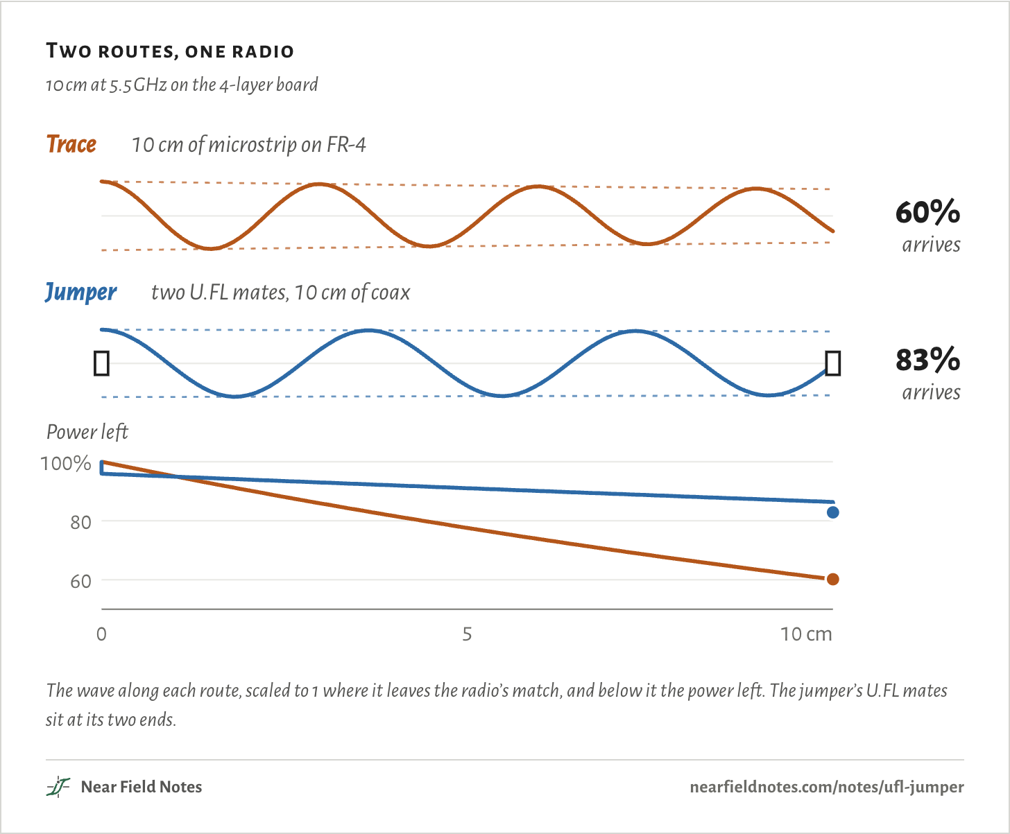
Past about 2.0 cm at 5.5 GHz on a common 4-layer board. Over 10 cm there, a trace delivers 60% of the radio’s power and a coax jumper between two U.FL connectors 83%. On a 2-layer board at 915 MHz, the trace wins up to 13.3 cm.

The trace loses the same share of its power in every centimeter, so its wave shrinks all the way to the antenna.

The jumper pays a small toll at each of its two connectors. In between, at 5.5 GHz, its coax loses a fifth as much per centimeter as the trace.

Two routes, one radio

10 cm at 5.5 GHz on the 4-layer board

Trace10 cm of microstrip on FR-460%arrivesJumpertwo U.FL mates, 10 cm of coax83%arrivesPower left6080100%0510 cmTrace10 cm of microstrip on FR-460%arrivesJumpertwo U.FL mates, 10 cm of coax83%arrivesPower left6080100%0510 cmTrace10 cm of microstrip on FR-460%arrivesJumpertwo U.FL mates, 10 cm of coax83%arrivesPower left6080100%0510 cm
The wave along each route, scaled to 1 where it leaves the radio’s match, and below it the power left. The jumper’s U.FL mates sit at its two ends.
The numbers
Power left at 5.5 GHz, as a share of what leaves the radio’s match. The jumper’s 100 mm row is before its second mate.
Distance from the radioTraceJumper
0 mm100%96%
20 mm90%94%
40 mm82%92%
60 mm74%90%
80 mm67%88%
100 mm60%86%
At the antenna60%83%

The board and its two routes

130 × 56 mm, 4 layers

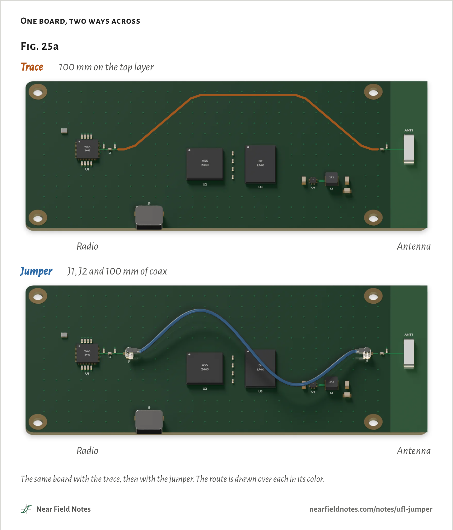
A Wi-Fi radio sits at the left end of the board and a chip antenna at the right. Between them are a processor, its DDR and a buck converter, with a USB-C port on the bottom edge.

The radio’s signal leaves its matching network and has 10 cm to cross. One way is a 50 Ω trace on the top layer, routed up along the board’s edge, around the busy middle.

The other is a U.FL receptacle at each end, J1 and J2, with a 100 mm coax jumper plugged between them. It goes straight over the DDR.

One board, two ways across
Fig. 25aTrace100 mm on the top layerRadioAntennaJumperJ1, J2 and 100 mm of coaxRadioAntennaFig. 25aTrace100 mm on the top layerRadioAntennaJumperJ1, J2 and 100 mm of coaxRadioAntennaFig. 25aTrace100 mm on the top layerRadioAntennaJumperJ1, J2 and 100 mm of coaxRadioAntenna
The same board with the trace, then with the jumper. The route is drawn over each in its color.
The numbers
PartWhat it is
U1Wi-Fi radio, QFN-48, with its match
ANT1Chip antenna, 10 × 3.2 mm, in a copper keep-out
U2, U3Processor and its DDR
U4, L2Buck converter and its inductor
J3USB-C receptacle
J1, J2U.FL receptacles, to Hirose’s U.FL-R-SMT-1 drawing
Trace0.373 mm wide, 100 mm long, on the top layer over the layer 2 plane
Jumper1.13 mm coax, 100 mm between plug centers

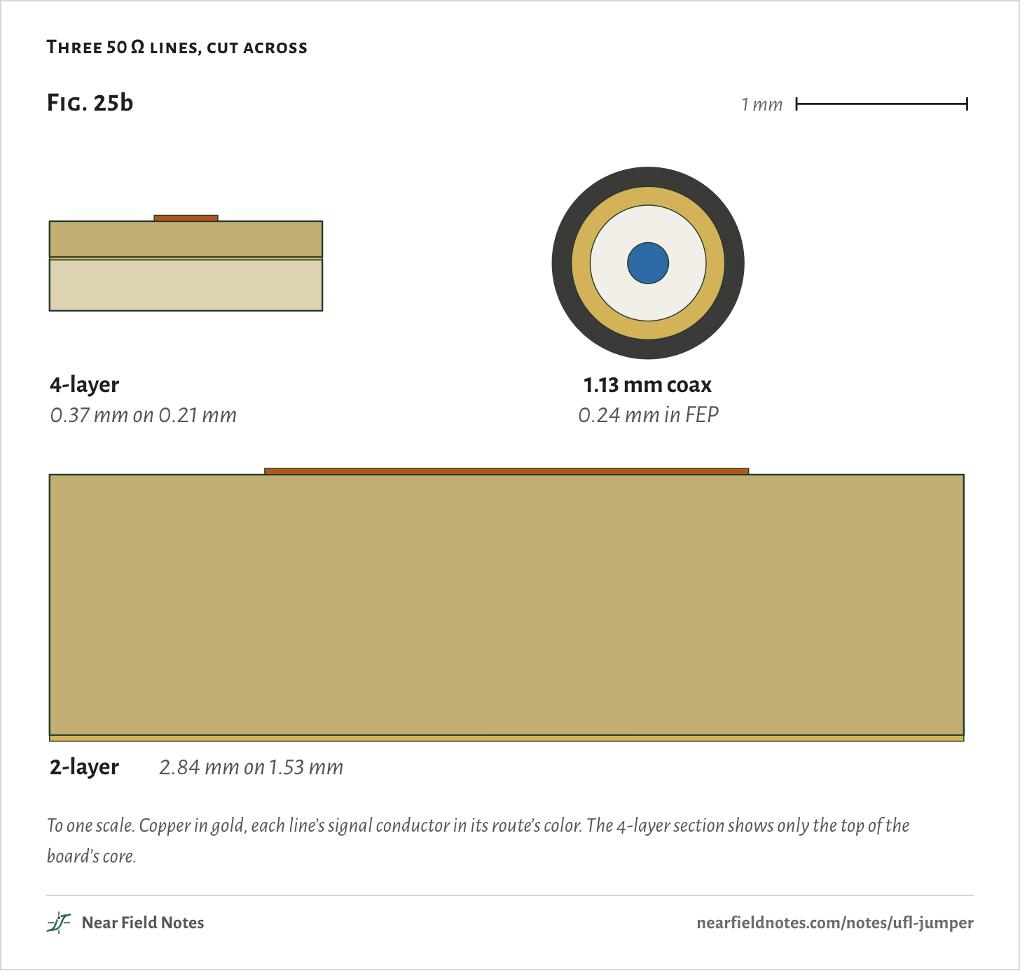
A trace’s width is set by how far its plane sits under it. On JLCPCB’s common 4-layer stack the plane is 0.21 mm down, so 50 Ω is 0.37 mm wide. On a 1.6 mm 2-layer board the plane is the bottom layer, 1.53 mm down, and 50 Ω is 2.84 mm wide.

Either way most of the field runs through the FR-4: 87% of its energy on the 4-layer board, 89% on the 2-layer one.

The jumper’s cable is 1.13 mm across. Its field stays inside the shield, in FEP, a plastic that loses far less than FR-4.

Three 50 Ω lines, cut across
Fig. 25b1 mm4-layer1.13 mm coax0.37 mm on 0.21 mm0.24 mm in FEP2-layer2.84 mm on 1.53 mmFig. 25b1 mm4-layer1.13 mm coax0.37 mm on 0.21 mm0.24 mm in FEP2-layer2.84 mm on 1.53 mmFig. 25b1 mm4-layer1.13 mm coax0.37 mm on 0.21 mm0.24 mm in FEP2-layer2.84 mm on 1.53 mm
To one scale. Copper in gold, each line’s signal conductor in its route’s color. The 4-layer section shows only the top of the board’s core.
The numbers
Trace Z₀ and εeff from the 2D field solve, 1 oz copper. Coax from Taoglas’s cable sheet.
LineConductorDielectricεrZ₀εeff
4-layer trace0.373 mm0.2104 mm, 7628 prepreg4.449.8 Ω3.19
2-layer trace2.838 mm1.53 mm, FR-4 core4.549.8 Ω3.36
1.13 mm coax0.24 mm center0.68 mm FEP, 0.90 mm shield2.150 Ω2.1

A trace loses in every centimeter

Copper and FR-4

A trace gives up the same share of its power in each centimeter. In decibels that adds up along the run:

Ltrace=αd

=0.223 dB/cm×10 cm=2.23 dB

That is the 4-layer board at 5.5 GHz. Decibels turn back into the share that arrives:

PP0=10−L/10

=10−2.23 dB/10=60%

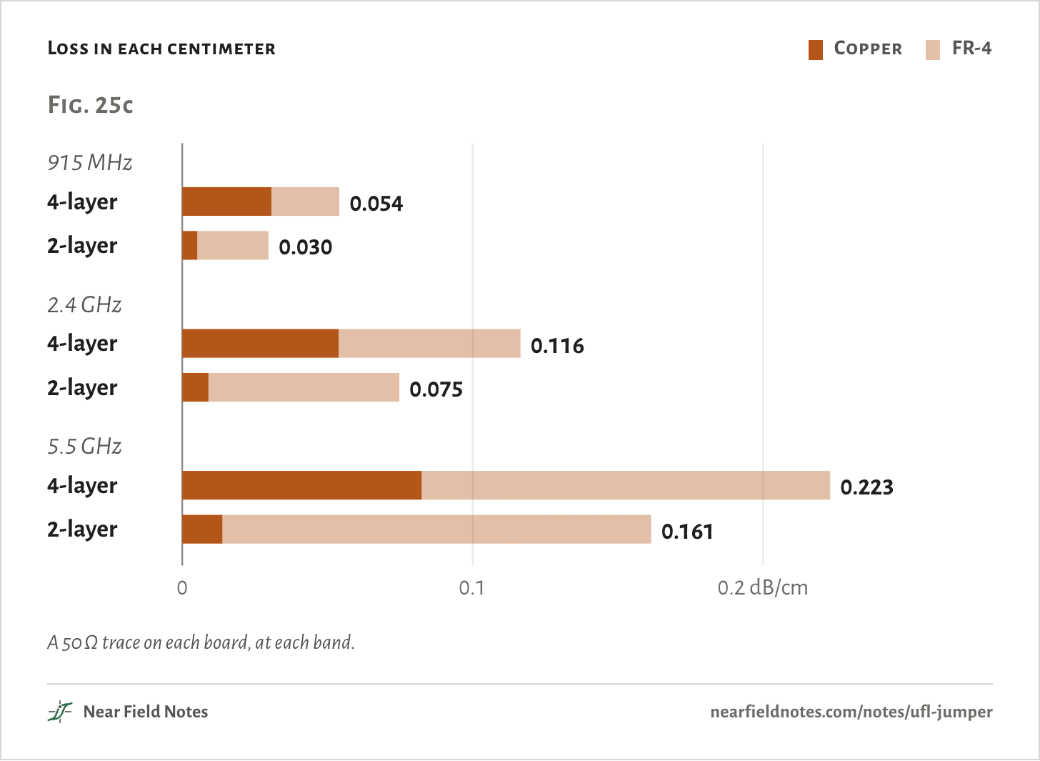
Most of the loss heats the FR-4, and that part grows in step with frequency:

αFR-4=8.686×πfcεeffqtan δ

=8.686×π × 5.5 GHz3.00 × 10⁸ m/s×3.19×0.87×0.018=14.1 dB/m=0.141 dB/cm

The copper’s part grows only with the square root of frequency, so above 1.8 GHz the FR-4 takes the larger share on the 4-layer board.

Loss in each centimeter
  • Copper
  • FR-4
Fig. 25c00.10.2 dB/cm915 MHz4-layer0.0542-layer0.0302.4 GHz4-layer0.1162-layer0.0755.5 GHz4-layer0.2232-layer0.161Fig. 25c00.10.2 dB/cm915 MHz4-layer0.0542-layer0.0302.4 GHz4-layer0.1162-layer0.0755.5 GHz4-layer0.2232-layer0.161Fig. 25c00.10.2 dB/cm915 MHz4-layer0.0542-layer0.0302.4 GHz4-layer0.1162-layer0.0755.5 GHz4-layer0.2232-layer0.161
A 50 Ω trace on each board, at each band.
The numbers
1 oz copper, Sq 3.2 µm, loss tangent 0.018, no solder mask.
Band, boardCopperFR-4Total, dB/cmFR-4’s share
915 MHz, 4-layer0.0310.0230.05443%
915 MHz, 2-layer0.0050.0250.03083%
2.4 GHz, 4-layer0.0540.0630.11654%
2.4 GHz, 2-layer0.0090.0660.07588%
5.5 GHz, 4-layer0.0820.1410.22363%
5.5 GHz, 2-layer0.0140.1480.16191%
482

A jumper pays at its connectors

Two mates, then the cable

A jumper’s loss comes in two parts: a fixed toll at its two mates, and its cable, which loses little per centimeter. Linx’s figures for its U.FL jumpers grow with the square root of frequency, so both parts do:

Ljumper=(A+Bd)f

=(0.153 dB+0.0195 dB/cm×10 cm)×5.5=0.82 dB

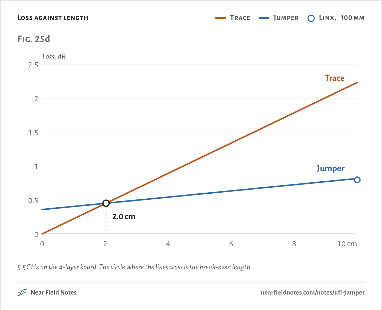
That is a 10 cm jumper at 5.5 GHz, and 83% of the power arrives. With no cable at all, the two mates alone would cost 0.36 dB. The jumper starts behind and catches the trace within a few centimeters.

Loss against length
  • Trace
  • Jumper
  • Linx, 100 mm
Fig. 25dLoss, dB0.511.522.500246810 cmTraceJumper2.0 cmFig. 25dLoss, dB0.511.522.500246810 cmTraceJumper2.0 cmFig. 25dLoss, dB0.511.522.500246810 cmTraceJumper2.0 cm
5.5 GHz on the 4-layer board. The circle where the lines cross is the break-even length.
The numbers
5.5 GHz, 4-layer board. The Linx row is its 100 mm figure, 0.34√f dB, against the fit’s 0.82 dB.
LengthTrace lossJumper lossTrace deliversJumper delivers
0 cm0.00 dB0.36 dB100%92%
1 cm0.22 dB0.41 dB95%91%
2 cm0.45 dB0.45 dB90%90%
4 cm0.89 dB0.54 dB81%88%
6 cm1.34 dB0.63 dB73%86%
8 cm1.78 dB0.73 dB66%85%
10 cm2.23 dB0.82 dB60%83%
Linx, 100 mm0.80 dB83%
484

Where the lines cross

Every frequency, both boards

Set the two losses equal and solve for the length where neither route wins:

deven=Afα−Bf

=0.153 dB × 5.50.223 dB/cm − 0.0195 dB/cm × 5.5=2.0 cm

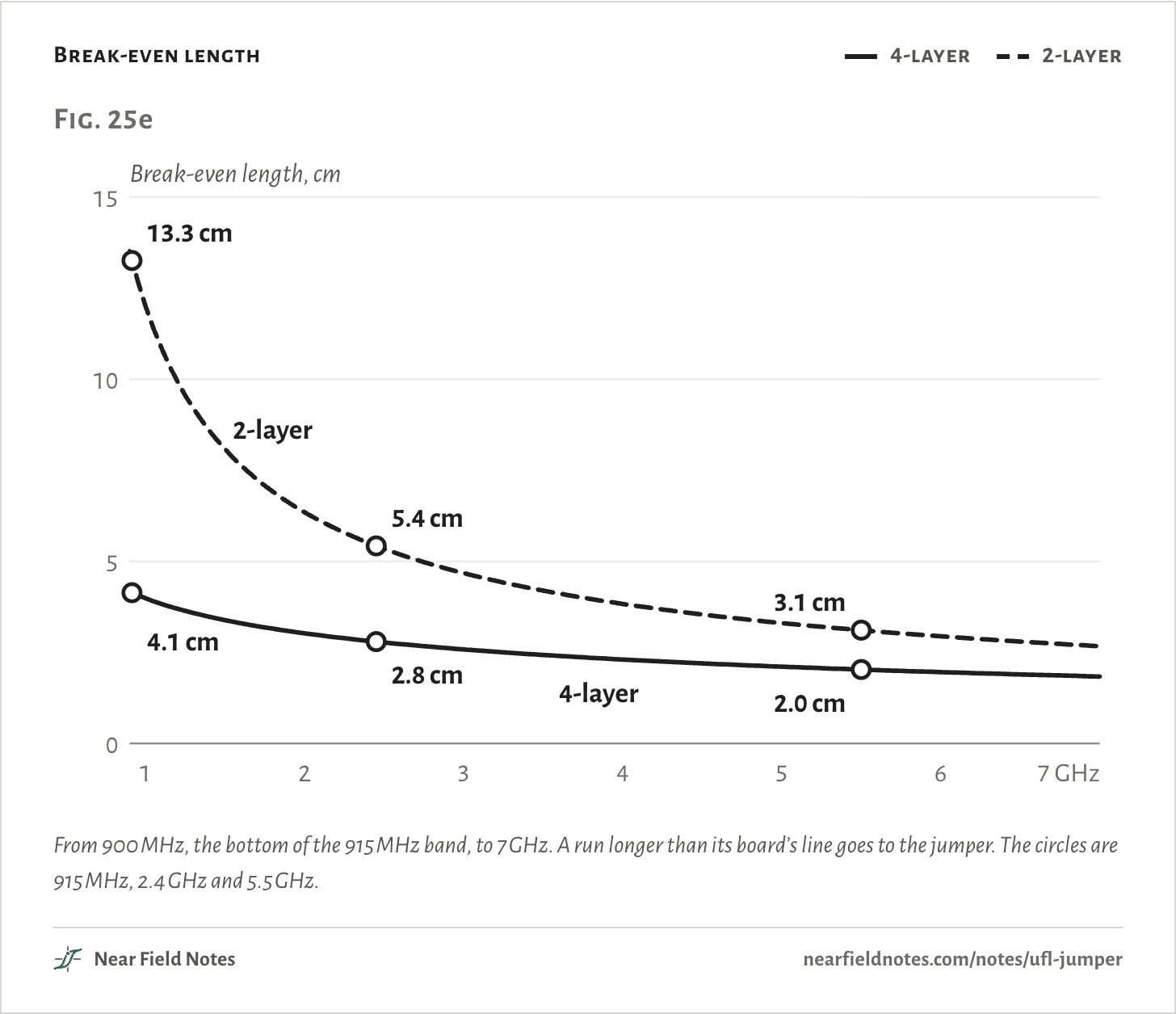
Shorter than that, the trace delivers more. Longer, the jumper does. A lower band, or more FR-4 between the trace and its plane, pushes the length out.

Break-even length
  • 4-layer
  • 2-layer
Fig. 25eBreak-even length, cm5101501247 GHz4.1 cm13.3 cm2.8 cm5.4 cm2.0 cm3.1 cmFig. 25eBreak-even length, cm5101501234567 GHz2-layer4-layer4.1 cm13.3 cm2.8 cm5.4 cm2.0 cm3.1 cmFig. 25eBreak-even length, cm5101501234567 GHz2-layer4-layer4.1 cm13.3 cm2.8 cm5.4 cm2.0 cm3.1 cm
From 900 MHz, the bottom of the 915 MHz band, to 7 GHz. A run longer than its board’s line goes to the jumper. The circles are 915 MHz, 2.4 GHz and 5.5 GHz.
The numbers
Break-even length with Linx’s jumper. Shorter runs go to the trace, longer ones to the jumper.
Frequency4-layer2-layer
900 MHz4.2 cm13.5 cm
915 MHz4.1 cm13.3 cm
2.4 GHz2.8 cm5.4 cm
5.5 GHz2.0 cm3.1 cm
7 GHz1.8 cm2.7 cm
486

Shielding, hands and cost

What loss leaves out

The jumper’s coax is shielded, so it can cross parts the trace has to avoid. In Fig. 25a the trace detours along the board’s top edge, clear of the processor, its DDR and the buck. The jumper runs straight across the DDR and past the buck.

Fast digital parts and ports make noise in a radio’s band. Intel measured the 2.4 GHz noise floor about 20 dB higher beside a USB 3.0 hard drive, and about 25 dB higher at a notebook’s USB 3.0 port. A route that picks up that noise brings it to the antenna.

The catch is the cable. The receptacles go on with the other parts, but the cable is plugged in by hand. Hirose, I-PEX and TE test their mates to 30 cycles. At 1,000 pieces, two receptacles and a cable cost $1.26 to $3.33 at Digi-Key, as listed on 5 November 2026. That price is for a 50 mm cable, half the length of the board’s. The trace costs only its copper.

Choosing a route

Loss, noise and the link

Length and band settle most cases. When they don’t, what lies along the route and how much range you need decide.

Key to the RF route

Trace or jumper?

  1. 1aThe run is shorter than its board’s line in Fig. 25eTrace
  2. 1bLongerGo to 2
  3. 2aThe straight path crosses DDR, a buck or USB 3Jumper
  4. 2bThe path is clearGo to 3
  5. 3aThe link needs the decibels the trace losesJumper
  6. 3bIt can spare themTrace

The board in Fig. 25a ends at 2a: 10 cm at 5.5 GHz, past the DDR. Its jumper saves 1.41 dB over the trace. Range in free space grows as 101.41 dB/20=1.18, so that is 18% farther.

Route it yourself

Three bands, two boards, 1 to 30 cm

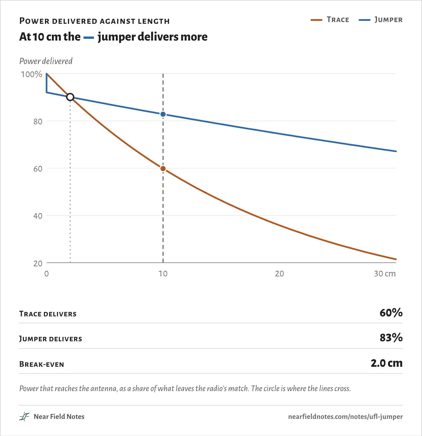
Choose a band, a board and a length. Each line is the share of the radio’s power that reaches the antenna. The jumper’s starts lower, after its mates, and falls more slowly.

Where the lines cross is the break-even length of Fig. 25e.

Band
Board
10 cm
Power delivered against length

At 10 cm the jumper delivers more

  • Trace
  • Jumper
Power delivered0102030 cm60708090100%8090100%406080100%50709020406080100%30507090Power delivered0102030 cm60708090100%8090100%406080100%50709020406080100%30507090Power delivered0102030 cm60708090100%8090100%406080100%50709020406080100%30507090
Trace delivers
60%
Jumper delivers
83%
Break-even
2.0 cm
Power that reaches the antenna, as a share of what leaves the radio’s match. The circle is where the lines cross.
The numbers
Power delivered, trace / jumper.
Band, board2 cm5 cm10 cm20 cm30 cmBreak-even
915 MHz, 4-layer98% / 96%94% / 95%88% / 93%78% / 89%69% / 85%4.1 cm
915 MHz, 2-layer99% / 96%97% / 95%93% / 93%87% / 89%81% / 85%13.3 cm
2.4 GHz, 4-layer95% / 93%87% / 91%76% / 88%58% / 82%45% / 77%2.8 cm
2.4 GHz, 2-layer97% / 93%92% / 91%84% / 88%71% / 82%60% / 77%5.4 cm
5.5 GHz, 4-layer90% / 90%77% / 87%60% / 83%36% / 75%21% / 67%2.0 cm
5.5 GHz, 2-layer93% / 90%83% / 87%69% / 83%48% / 75%33% / 67%3.1 cm

Conditions

Board
130 × 56 mm, 1.6 mm thick. The 4-layer case uses JLCPCB’s JLC04161H-7628 stack: 0.2104 mm of 7628 prepreg under the top layer, εr 4.4. The 2-layer case puts the trace 1.53 mm over the bottom layer, εr 4.5.
Trace
50 Ω microstrip, 1 oz copper, no solder mask: 0.37 mm wide on the 4-layer board and 2.84 mm on the 2-layer one, both 49.8 Ω by the 2D solve. Loss tangent 0.018 and copper roughness Sq 3.2 µm, the Hammerstad roughness model.
Jumper
Linx’s CSI-UFFR U.FL-to-U.FL 1.13 mm jumpers, as the straight-line fit of their 100, 200 and 300 mm figures in the jumper’s formula above. The opening figure splits the mates’ share evenly between its two ends.
Bands
915 MHz, 2.4 GHz taken at 2.45 GHz, and 5.5 GHz.
Trace loss
A 2D field solve of each cross-section: copper by incremental inductance, FR-4 by the share of the field’s energy in it.
Opening
The trace’s wave is the field in the FR-4 under its center line, from an openEMS run of the 10 cm 4-layer line at 5.5 GHz. That run’s S21 is −2.21 dB, 60% delivered, and its field falls 0.221 dB/cm against 0.223 dB/cm from the 2D solve. The power line below it follows that fitted fall. Its wavelength on the board is 29.9 mm. The jumper’s wave uses the coax’s wavelength from an openEMS run of the cable, 36.5 mm, and the Linx loss.
Video
The video used an earlier run of the 2D solve that read copper loss about 13% low. Its 61% is 60% here, and its 2.1, 3.0 and 14 cm are 2.0 cm, 2.8 cm and 13.3 cm.
Renders
Blender. Parts from their datasheet outlines, the U.FL receptacles from Hirose’s drawing.

Simulated only. Nothing on this page has been measured on a board yet.

Limits

  • Linx rates these jumpers from DC to 3 GHz. Above that its square-root law is carried past its range. I-PEX’s 5.8 GHz figure is lower.
  • TE allows up to 0.24 dB for each of its U.FL-style mates to 6 GHz, 0.48 dB for two, more than the Linx line’s 0.36 dB at 5.5 GHz.
  • Each mate’s reflection is inside the jumper’s figures, not modeled on its own.
  • Solder mask over the trace would add a little loss.
  • Noise pickup isn’t simulated. Intel’s figures are near-field probe readings in the 2.4 GHz band, not noise on a trace.
  • Bends and vias aren’t counted. A trace that changes layers pays at each via too, as Note 17 shows.

Files

  • post/site.pyTrace loss on both boards, the jumper’s line and every break-even length on this page
  • post/tradeoff.pyThe Linx and I-PEX jumper fits
  • sim/stack.pyThe two stack-ups and their 50 Ω widths
  • sim/fields.pyThe openEMS runs of the 10 cm line and the coax at 5.5 GHz
  • render/site.pyThe board renders in Fig. 25a
  • render/board.pyThe board, its parts and both routes

Sources

Like this note?

Rev 1 ·
  1. Rev 1First published

Each fix gets a line here, with the reader's name if they want credit.

Did it answer your question?

Want more on this?

Report a problem

What should the next note be? Ask for one