Near Field Notes

Note 20PowerRev 1Watch the video · 0:19

FET choice

Is the FET with the lowest Rds(on) the best one?

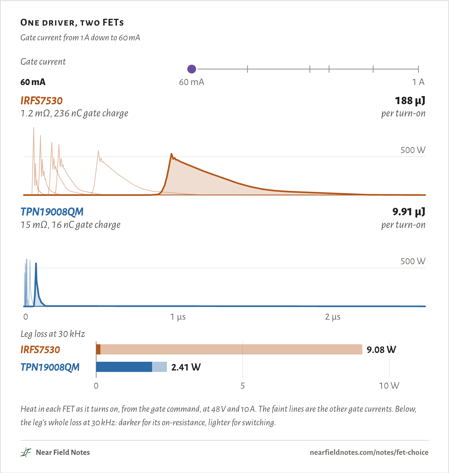
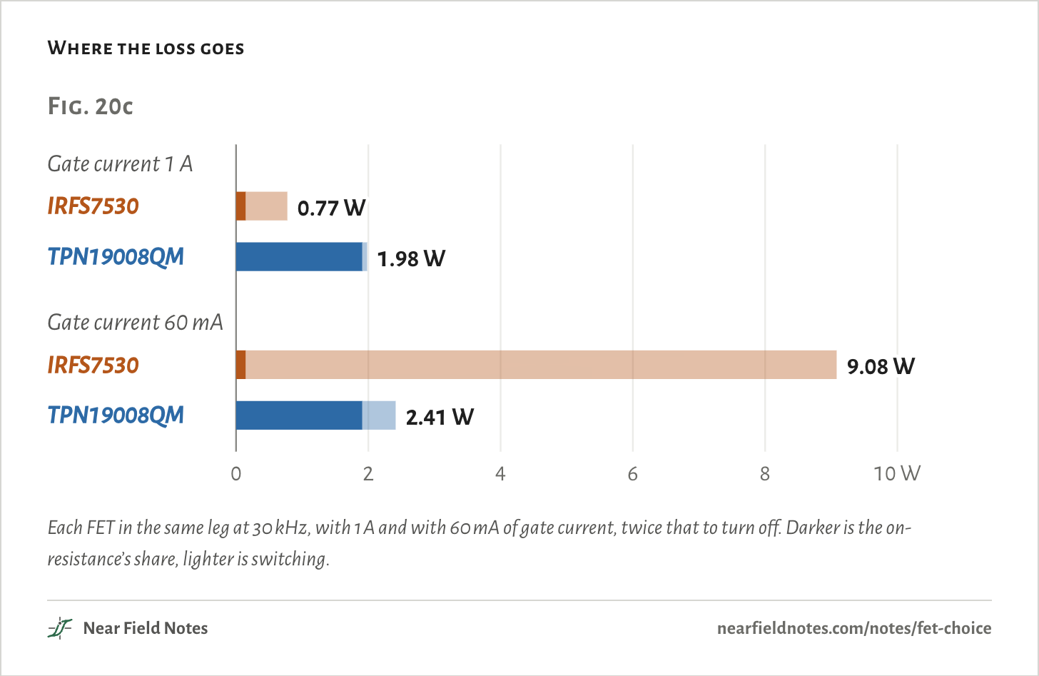
Only with a fast gate driver. In moteus-c1’s 48 V, 10 A half bridge at 30 kHz, the 1.2 mΩ IRFS7530 loses 0.77 W and the 15 mΩ TPN19008QM 1.98 W with 1 A of gate current. At 60 mA they lose 9.08 W and 2.41 W.

The figure drives both FETs from the same gate driver and steps its current down from 1 A to 60 mA. The IRFS7530’s 236 nC gate takes longer to fill at every step, and its turn-on heat climbs from 13.0 µJ to 188 µJ.

The TPN19008QM holds 15 times less charge. Even at 60 mA it is half on for only 48 ns, and its leg’s loss barely moves.

One driver, two FETs

Gate current from 1 A down to 60 mA

Gate current60 mA60 mA1 AIRFS75301.2 mΩ, 236 nC gate charge188 µJper turn-on500 WTPN19008QM15 mΩ, 16 nC gate charge9.91 µJper turn-on500 W01 µs2 µsLeg loss at 30 kHz0510 WIRFS75309.08 WTPN19008QM2.41 WGate current60 mA60 mA1 AIRFS75301.2 mΩ, 236 nC gate charge188 µJper turn-on500 WTPN19008QM15 mΩ, 16 nC gate charge9.91 µJper turn-on500 W01 µs2 µsLeg loss at 30 kHz0510 WIRFS75309.08 WTPN19008QM2.41 WGate current60 mA60 mA1 AIRFS75301.2 mΩ, 236 nC gate charge188 µJper turn-on500 WTPN19008QM15 mΩ, 16 nC gate charge9.91 µJper turn-on500 W01 µs2 µsLeg loss at 30 kHz0510 WIRFS75309.08 WTPN19008QM2.41 W
Heat in each FET as it turns on, from the gate command, at 48 V and 10 A. The faint lines are the other gate currents. Below, the leg’s whole loss at 30 kHz: darker for its on-resistance, lighter for switching.
The numbers
Turn-on heat beyond plain conduction, and the leg’s loss at 30 kHz. 48 V, 10 A.
Gate currentIRFS7530, a turn-onIRFS7530, leg lossTPN19008QM, a turn-onTPN19008QM, leg loss
1 A13.0 µJ0.77 W0.98 µJ1.98 W
570 mA21.1 µJ1.15 W1.44 µJ2.00 W
330 mA35.3 µJ1.82 W2.14 µJ2.02 W
260 mA44.3 µJ2.26 W2.60 µJ2.04 W
120 mA94.5 µJ4.66 W5.14 µJ2.17 W
60 mA188 µJ9.08 W9.91 µJ2.41 W

The half bridge and its gate driver

One phase of moteus-c1

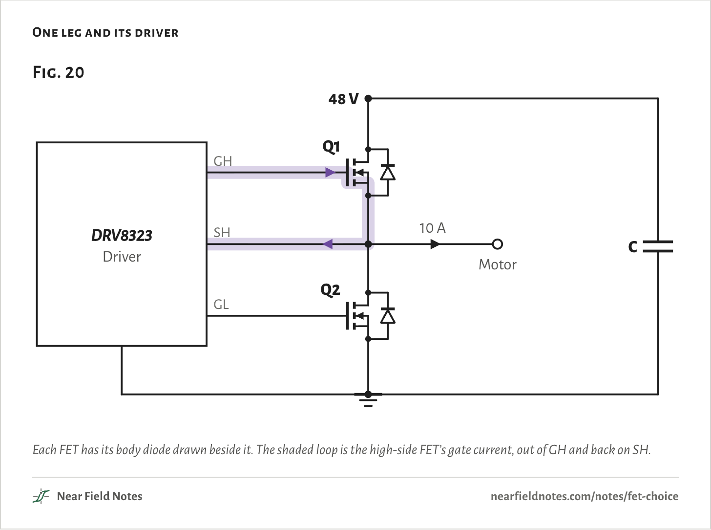
A motor driver connects each motor wire to the supply or to ground through two FETs, one above the other. Switching between the two thousands of times a second sets the motor’s current.

On moteus-c1 the supply is 48 V, and the switching runs at 30 kHz, its firmware’s default. This page takes 10 A out of one leg.

A gate driver turns each FET on by pushing current into its gate, and off by pulling it out. The DRV8323 sets that current in 16 steps from 10 mA to 1 A. It powers up at 1 A, and moteus-c1’s firmware turns it down to 60 mA to turn on and 20 mA to turn off.

One leg and its driver
Fig. 2048 VQ1Q2CMotor10 ADRV8323DriverGHSHGLFig. 2048 VQ1Q2CMotor10 ADRV8323DriverGHSHGLFig. 2048 VQ1Q2CMotor10 ADRV8323DriverGHSHGL
Each FET has its body diode drawn beside it. The shaded loop is the high-side FET’s gate current, out of GH and back on SH.
The numbers
PartWhat it is
Q1, Q2Both IRFS7530 or both TPN19008QM, n-channel
DriverDRV8323, 60 mA to 1 A into a gate, twice that out of it
Supply48 V
Motor10 A out of the switch node

Two FETs suit this leg. VESC 4.12 uses the IRFS7530, a 60 V part with 13 times less resistance. moteus-c1 uses the 80 V TPN19008QM.

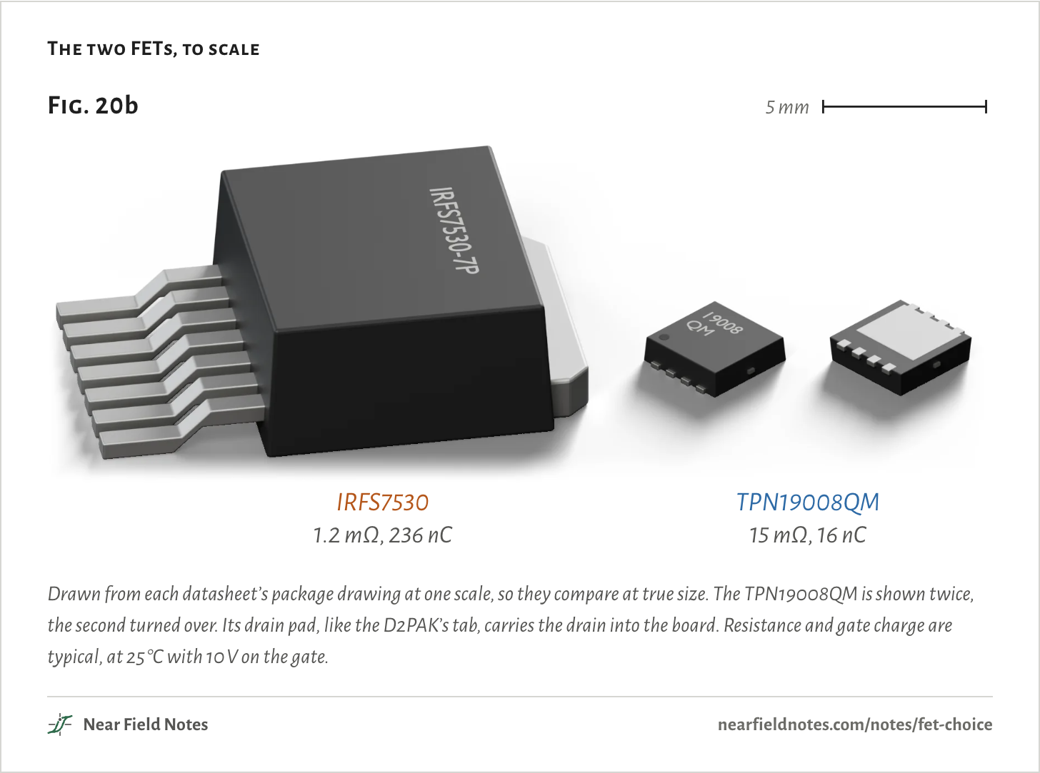
Low resistance takes a big die, and a big die has a big gate. The IRFS7530 holds 236 nC of gate charge against 16 nC, and its package takes 14 times the board.

The rest of the page puts each pair in the same leg in turn, with the same driver.

The two FETs, to scale
Fig. 20b5 mmIRFS75301.2 mΩ, 236 nCTPN19008QM15 mΩ, 16 nCFig. 20b5 mmIRFS75301.2 mΩ, 236 nCTPN19008QM15 mΩ, 16 nCFig. 20b5 mmIRFS75301.2 mΩ, 236 nCTPN19008QM15 mΩ, 16 nC
Drawn from each datasheet’s package drawing at one scale, so they compare at true size. The TPN19008QM is shown twice, the second turned over. Its drain pad, like the D2PAK’s tab, carries the drain into the board. Resistance and gate charge are typical, at 25 °C with 10 V on the gate.
The numbers
Sizes from each datasheet’s package drawing. Datasheet typical values at 25 °C and 10 V on the gate.
PartPackageSizeDrainRds(on), typicalGate chargeRatedBoard
IRFS7530D2PAK-710.1 × 15.25 × 4.45 mmTab1.15 mΩ236 nC60 VVESC 4.12
TPN19008QMTSON Advance3.3 × 3.3 × 0.85 mmPad underneath14.7 mΩ16 nC80 Vmoteus-c1

Two ways to lose power

48 V, 10 A, 30 kHz

A FET loses power in two ways. While it is on, the motor’s current heats its resistance:

PR=I2R

=(10 A)²×1.45 mΩ=0.15 W

That is the IRFS7530. The TPN19008QM’s 19.1 mΩ loses 1.91 W, 13 times more. R is each FET’s resistance at 100 °C, and one FET or the other always carries the current, so this is the whole leg’s.

Every cycle also costs a fixed energy, while a FET is half on and the current changes hands between the two:

Psw=Ef

=21.0 µJ×30 kHz=0.63 W

E counts the whole cycle, with both edges, the dead time and the diode’s recovery. The 13.0 µJ turn-on in the opening figure is one part of the 21.0 µJ.

That is the IRFS7530 with 1 A of gate current. The TPN19008QM loses 2.43 µJ a cycle, so 0.07 W. At 60 mA the big FET’s switching costs 8.93 W.

Where the loss goes
Fig. 20c0510 WGate current 1 AIRFS75300.77 WTPN19008QM1.98 WGate current 60 mAIRFS75309.08 WTPN19008QM2.41 WFig. 20c0246810 WGate current 1 AIRFS75300.77 WTPN19008QM1.98 WGate current 60 mAIRFS75309.08 WTPN19008QM2.41 WFig. 20c0246810 WGate current 1 AIRFS75300.77 WTPN19008QM1.98 WGate current 60 mAIRFS75309.08 WTPN19008QM2.41 W
Each FET in the same leg at 30 kHz, with 1 A and with 60 mA of gate current, twice that to turn off. Darker is the on-resistance’s share, lighter is switching.
The numbers
At 48 V, 10 A and 30 kHz, on-resistance at 100 °C.
FET, gate currentOn-resistanceSwitchingLeg loss
IRFS7530, 1 A0.15 W0.63 W0.77 W
TPN19008QM, 1 A1.91 W0.07 W1.98 W
IRFS7530, 60 mA0.15 W8.93 W9.08 W
TPN19008QM, 60 mA1.91 W0.50 W2.41 W

The catch is the gate

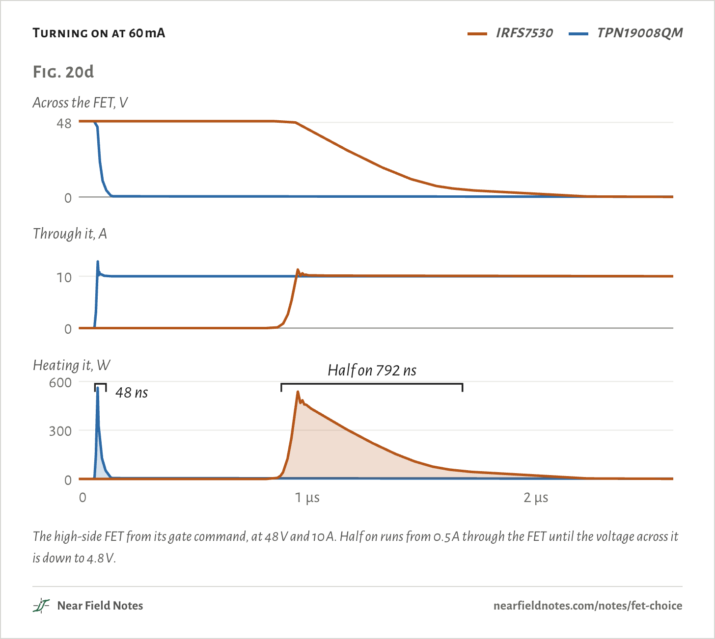
Both FETs turning on at 60 mA

Switching loss comes from the time a FET spends half on, and the gate sets that time. The driver fills the gate at a set current, so a gate that holds more charge takes longer:

tg=QgIg

=236 nC60 mA=3.9 µs

The TPN19008QM’s 16 nC fills in 0.27 µs.

Turning on at 60 mA
  • IRFS7530
  • TPN19008QM
Fig. 20dAcross the FET, V048Through it, A010Heating it, W030060001 µs2 µsHalf on 792 ns48 nsFig. 20dAcross the FET, V048Through it, A010Heating it, W030060001 µs2 µsHalf on 792 ns48 nsFig. 20dAcross the FET, V048Through it, A010Heating it, W030060001 µs2 µsHalf on 792 ns48 ns
The high-side FET from its gate command, at 48 V and 10 A. Half on runs from 0.5 A through the FET until the voltage across it is down to 4.8 V.
The numbers
Half on: from 0.5 A through it until the voltage is down to 4.8 V.
FETCurrent startsHalf onPeak heatTurn-on heat
IRFS7530886 ns792 ns538 W188 µJ
TPN19008QM71 ns48 ns561 W9.91 µJ
392

Which one wins

Every DRV8323 step, 10 A at 30 kHz

Add the two losses for the leg’s whole loss, and do it at every step the driver offers:

P=I2R+Ef

=0.15 W+298 µJ×30 kHz=9.08 W

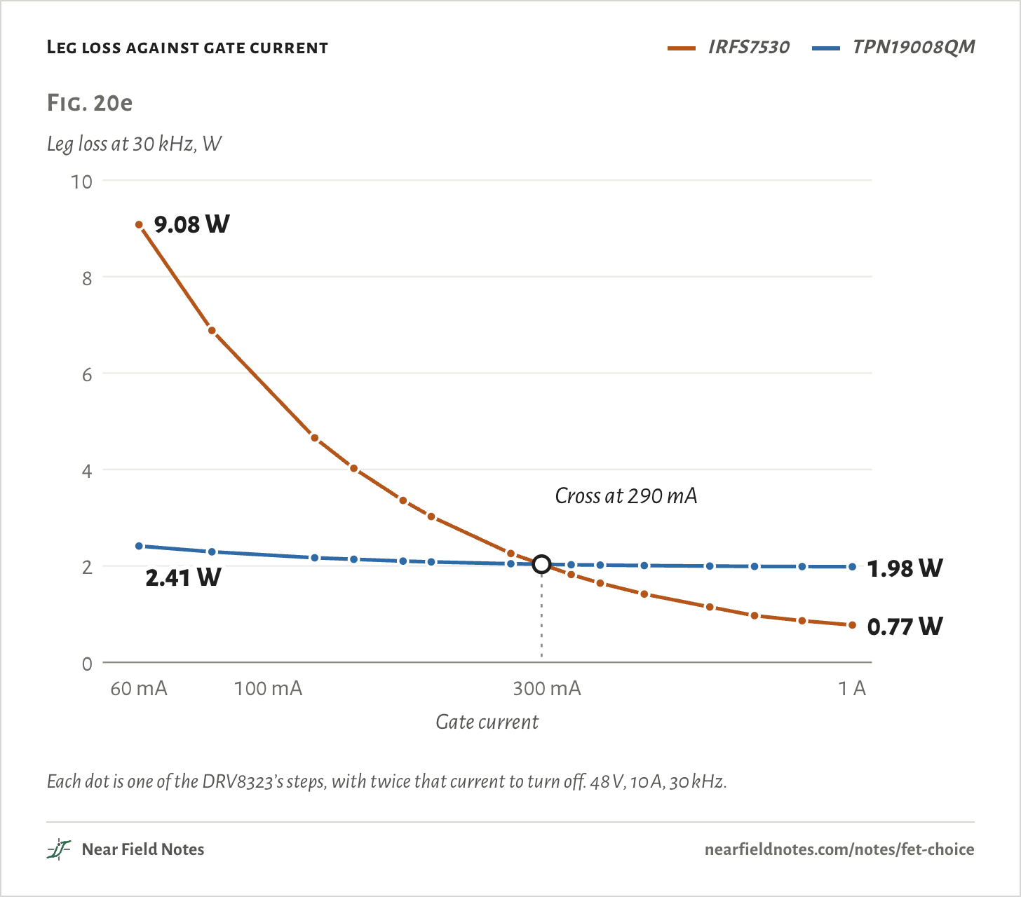
That is the IRFS7530 at 60 mA, the left end of its line in Fig. 20e.

Leg loss against gate current
  • IRFS7530
  • TPN19008QM
Fig. 20eLeg loss at 30 kHz, W024681060 mA300 mA1 AGate currentCross at 290 mA9.08 W2.41 W0.77 W1.98 WFig. 20eLeg loss at 30 kHz, W024681060 mA100 mA300 mA1 AGate currentCross at 290 mA9.08 W2.41 W0.77 W1.98 WFig. 20eLeg loss at 30 kHz, W024681060 mA100 mA300 mA1 AGate currentCross at 290 mA9.08 W2.41 W0.77 W1.98 W
Each dot is one of the DRV8323’s steps, with twice that current to turn off. 48 V, 10 A, 30 kHz.
The numbers
Leg loss at 30 kHz, 48 V, 10 A. Turn-off current is twice the turn-on current.
Gate currentIRFS7530TPN19008QM
60 mA9.08 W2.41 W
80 mA6.88 W2.29 W
120 mA4.66 W2.17 W
140 mA4.02 W2.14 W
170 mA3.36 W2.10 W
190 mA3.02 W2.08 W
260 mA2.26 W2.04 W
330 mA1.82 W2.02 W
370 mA1.64 W2.02 W
440 mA1.42 W2.01 W
570 mA1.15 W2.00 W
680 mA0.97 W1.99 W
820 mA0.86 W1.98 W
1 A0.77 W1.98 W
394

Why a driver runs slow

The FET that is off, as the other turns on

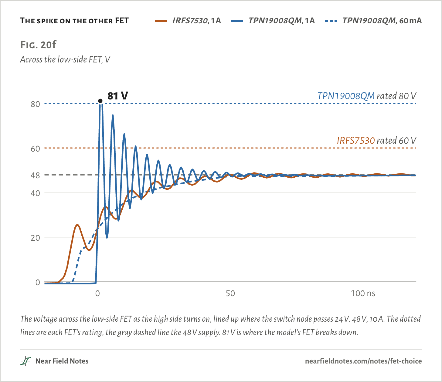
If a fast gate lets the big FET win, why turn a driver down? A fast edge makes the loop’s inductance ring, and the FET that is off takes the spike. Note 4 follows it through moteus-c1’s copper.

At 1 A the TPN19008QM rings up to its breakdown, 81 V in the model, past its 80 V rating. At 60 mA it peaks at 47.8 V.

The IRFS7530’s 13.0 nF gate slows its own edge, so even at 1 A it peaks at 48.8 V. Its rating is 60 V, though, so a 48 V supply leaves it 12 V.

moteus-c1’s firmware runs 60 mA on and 20 mA off. With that setting the TPN19008QM’s leg loses 3.19 W. A pair of IRFS7530 would lose 23.9 W.

The spike on the other FET
  • IRFS7530, 1 A
  • TPN19008QM, 1 A
  • TPN19008QM, 60 mA
Fig. 20fAcross the low-side FET, V020404860IRFS7530 rated 60 V80TPN19008QM rated 80 V050100 ns81 VFig. 20fAcross the low-side FET, V020404860IRFS7530 rated 60 V80TPN19008QM rated 80 V050100 ns81 VFig. 20fAcross the low-side FET, V020404860IRFS7530 rated 60 V80TPN19008QM rated 80 V050100 ns81 V
The voltage across the low-side FET as the high side turns on, lined up where the switch node passes 24 V. 48 V, 10 A. The dotted lines are each FET’s rating, the gray dashed line the 48 V supply. 81 V is where the model’s FET breaks down.
The numbers
Lined up where the switch node passes 24 V. 48 V, 10 A. 81 V is where the model’s TPN19008QM breaks down.
FET, gate currentPeakRated
TPN19008QM, 1 A81.2 V80 V
TPN19008QM, 60 mA47.8 V80 V
IRFS7530, 1 A48.8 V60 V

Current and frequency move the line

Where both FETs lose the same

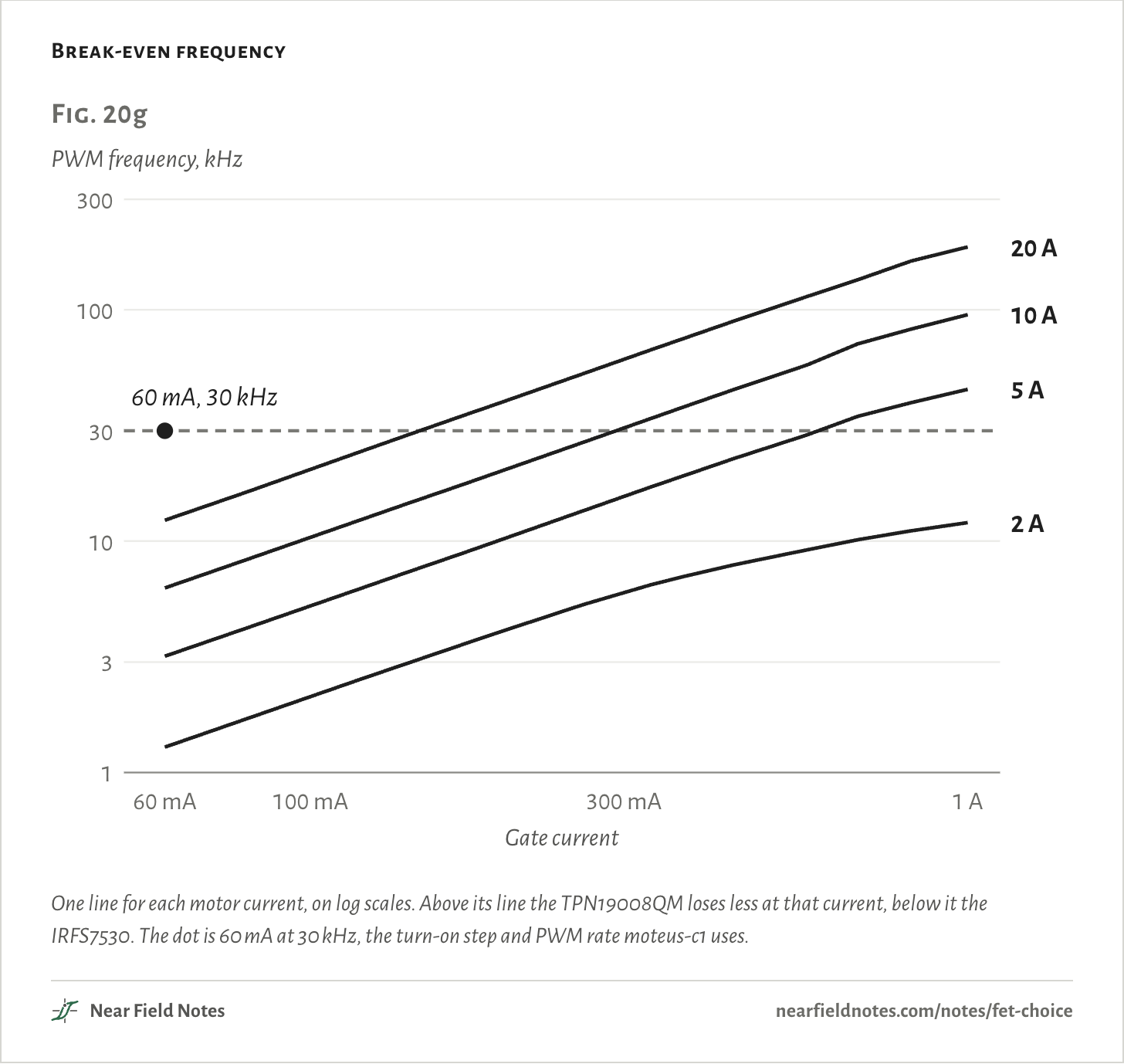
Fig. 20e holds for one motor current and one PWM frequency. Set the two losses equal and solve for the frequency where neither FET wins:

feven=I2(R2−R1)E1−E2

=(10 A)² × 17.6 mΩ18.5 µJ=95 kHz

That is 10 A with 1 A of gate current. Above that frequency the TPN19008QM loses less, and below it the IRFS7530.

Break-even frequency
Fig. 20gPWM frequency, kHz13101003003060 mA300 mA1 AGate current2 A5 A10 A20 A60 mA, 30 kHzFig. 20gPWM frequency, kHz13101003003060 mA100 mA300 mA1 AGate current2 A5 A10 A20 A60 mA, 30 kHzFig. 20gPWM frequency, kHz13101003003060 mA100 mA300 mA1 AGate current2 A5 A10 A20 A60 mA, 30 kHz
One line for each motor current, on log scales. Above its line the TPN19008QM loses less at that current, below it the IRFS7530. The dot is 60 mA at 30 kHz, the turn-on step and PWM rate moteus-c1 uses.
The numbers
PWM frequency where both FETs lose the same, at each motor current.
Gate current2 A5 A10 A15 A20 A
60 mA1.3 kHz3.2 kHz6.3 kHz9.3 kHz12 kHz
80 mA1.7 kHz4.2 kHz8.3 kHz12 kHz16 kHz
120 mA2.5 kHz6.3 kHz12 kHz19 kHz25 kHz
140 mA3.0 kHz7.3 kHz14 kHz22 kHz29 kHz
170 mA3.6 kHz8.8 kHz18 kHz26 kHz35 kHz
190 mA4.0 kHz9.9 kHz20 kHz29 kHz39 kHz
260 mA5.3 kHz14 kHz27 kHz40 kHz53 kHz
330 mA6.5 kHz17 kHz34 kHz51 kHz67 kHz
370 mA7.0 kHz19 kHz38 kHz57 kHz75 kHz
440 mA7.9 kHz23 kHz45 kHz67 kHz89 kHz
570 mA9.2 kHz29 kHz58 kHz86 kHz114 kHz
680 mA10 kHz35 kHz71 kHz106 kHz135 kHz
820 mA11 kHz40 kHz82 kHz123 kHz162 kHz
1 A12 kHz45 kHz95 kHz141 kHz187 kHz
396

Choosing a FET

Two FETs, one 48 V leg

The answer turns on how hard the driver pushes the gate and how often the leg switches. The key sorts them.

Key to FET choice

Which FET for your drive?

  1. 1aThe driver turns the gate on with 140 mA or lessGo to 2
  2. 1bWith moreGo to 3
  3. 2aThe PWM runs at 30 kHz or fasterThe one with less gate charge
  4. 2bSlowerGo to 3
  5. 3aThe PWM runs above your motor current’s line in Fig. 20gThe one with less gate charge
  6. 3bBelow itThe one with lower Rds(on)

For these two FETs on a 48 V leg, at 2 to 20 A. Another pair has its own lines, from P=I2R+Ef. moteus-c1 turns its gates on at 60 mA and runs at 30 kHz, so it ends at 2a. Its 20 mA turn-off widens the gap. The TPN19008QM’s leg loses 3.19 W, a pair of IRFS7530 23.9 W.

Pick the FET yourself

Every gate current and motor current

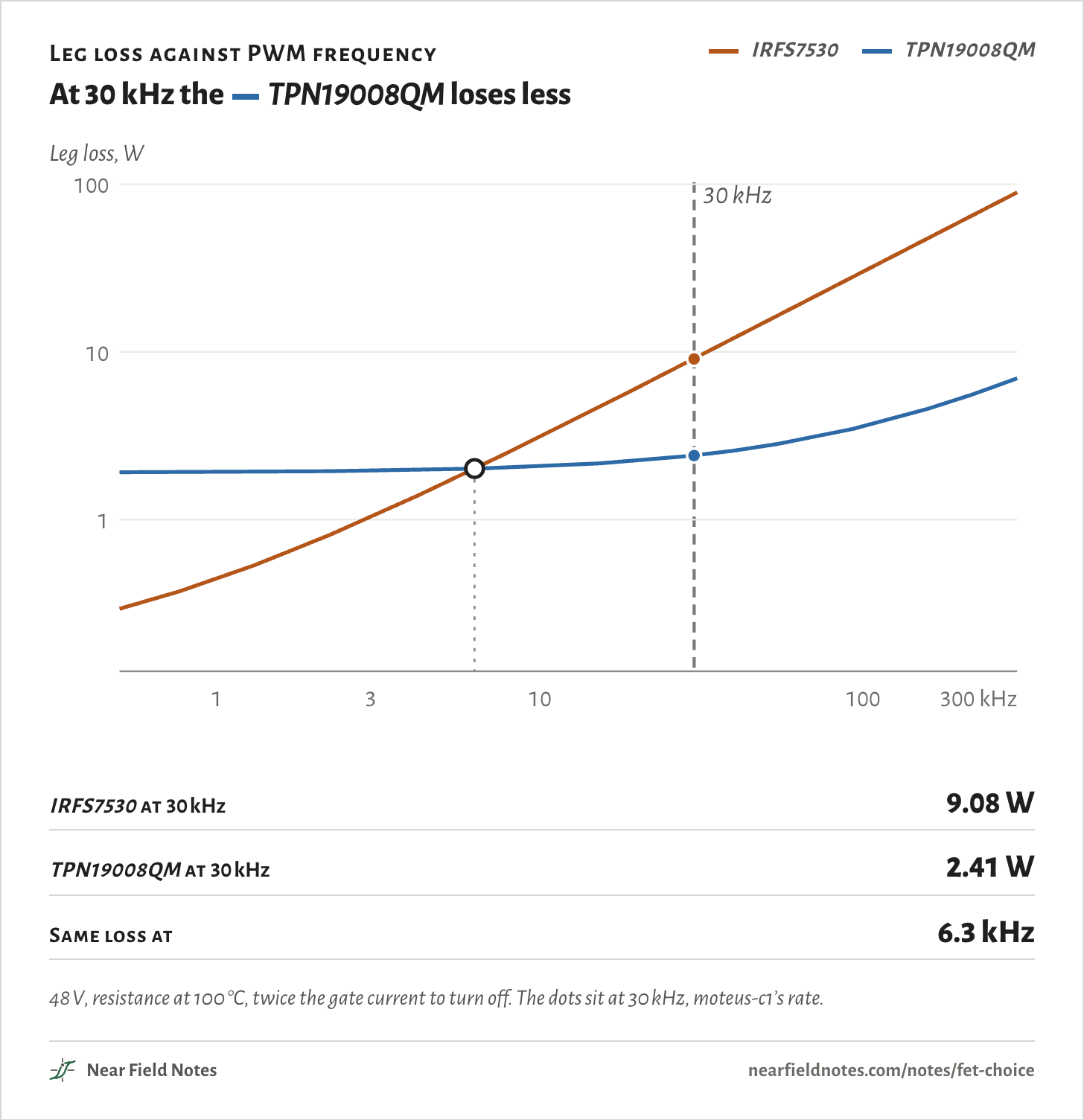
Choose a gate current and a motor current. Against PWM frequency each FET’s loss starts flat at its resistance loss, then climbs as its switching energy is paid more often. Both scales are logarithmic.

Where the two lines cross is the break-even frequency of Fig. 20g.

60 mA
Motor current
Leg loss against PWM frequency

At 30 kHz the TPN19008QM loses less

  • IRFS7530
  • TPN19008QM
Leg loss, W110100 kHz30 kHz0.010.11100.1110110100110100110100Leg loss, W1310100300 kHz30 kHz0.010.11100.1110110100110100110100Leg loss, W1310100300 kHz30 kHz0.010.11100.1110110100110100110100
IRFS7530 at 30 kHz
9.08 W
TPN19008QM at 30 kHz
2.41 W
Same loss at
6.3 kHz
48 V, resistance at 100 °C, twice the gate current to turn off. The dots sit at 30 kHz, moteus-c1’s rate.
The numbers
Leg loss at 30 kHz at each motor current: IRFS7530 / TPN19008QM.
Gate current2 A5 A10 A15 A20 A
60 mA1.74 / 0.17 W4.43 / 0.71 W9.08 / 2.41 W13.92 / 5.10 W18.92 / 8.76 W
80 mA1.32 / 0.16 W3.35 / 0.66 W6.88 / 2.29 W10.58 / 4.90 W14.41 / 8.49 W
120 mA0.90 / 0.14 W2.26 / 0.60 W4.66 / 2.17 W7.17 / 4.71 W9.78 / 8.22 W
140 mA0.78 / 0.13 W1.96 / 0.59 W4.02 / 2.14 W6.20 / 4.65 W8.47 / 8.14 W
170 mA0.65 / 0.13 W1.63 / 0.58 W3.36 / 2.10 W5.18 / 4.60 W7.10 / 8.06 W
190 mA0.59 / 0.13 W1.46 / 0.57 W3.02 / 2.08 W4.68 / 4.57 W6.42 / 8.02 W
260 mA0.45 / 0.12 W1.09 / 0.55 W2.26 / 2.04 W3.52 / 4.50 W4.87 / 7.93 W
330 mA0.37 / 0.12 W0.87 / 0.54 W1.82 / 2.02 W2.85 / 4.47 W3.97 / 7.88 W
370 mA0.35 / 0.12 W0.79 / 0.54 W1.64 / 2.02 W2.59 / 4.45 W3.62 / 7.86 W
440 mA0.31 / 0.12 W0.68 / 0.54 W1.42 / 2.01 W2.24 / 4.44 W3.15 / 7.84 W
570 mA0.27 / 0.11 W0.55 / 0.53 W1.15 / 2.00 W1.83 / 4.42 W2.60 / 7.81 W
680 mA0.25 / 0.11 W0.47 / 0.53 W0.97 / 1.99 W1.56 / 4.41 W2.30 / 7.79 W
820 mA0.23 / 0.11 W0.42 / 0.53 W0.86 / 1.98 W1.40 / 4.40 W2.02 / 7.78 W
1 A0.22 / 0.11 W0.38 / 0.53 W0.77 / 1.98 W1.27 / 4.39 W1.84 / 7.77 W

Conditions

Board
One leg of moteus-c1 r1.2, with the loop inductances of its copper from the field runs in Note 4. Each FET pair takes the same place in it.
FETs
The IRFS7530 and the TPN19008QM, as models fitted by hand to their datasheets, within 7% of them except the small FET’s gate-drain charge, 26% high.
Driver
A DRV8323 model built from its datasheet: every step from 60 mA to 1 A to turn on, twice that to turn off, with its drive time, tDRIVE, at its longest, 4 µs, so the big FET’s gate fills at the set current. moteus-c1’s own setting, 60 mA on and 20 mA off, is two more runs.
Load
48 V, with 10 A held steady over each edge. 2 to 20 A in Fig. 20g and the explorer.
Resistance
Each model’s own on-resistance in the leg at 10 A, 1.04 mΩ and 13.8 mΩ. That is below the datasheets’ typicals because the driver puts 11 V on the gate, against their 10 V. Times each datasheet’s rise from 25 to 100 °C, 1.40 and 1.38, that gives 1.45 mΩ and 19.1 mΩ.
Lost
Everything both FETs dissipate over one PWM cycle beyond their resistance’s share at 25 °C: both edges, the body diode through the dead time, its recovery and the FETs’ capacitance.
Renders
Blender, one camera. Outsides from each datasheet’s package drawing.
Solver
ngspice: 142 runs of the whole cycle, 28 turn-ons for the opening and Fig. 20d, and 3 for Fig. 20f.

Simulated only. Nothing on this page has been measured on a board yet.

Limits

  • The IRFS7530 sits in moteus-c1’s small copper loop. Its larger package would need a larger loop, with more inductance.
  • 81 V is the small FET model’s breakdown. From 820 mA up its ring reaches it, so the real peak would be higher.
  • The driver’s own power isn’t counted: 0.16 W for a pair of IRFS7530 at 30 kHz, 0.01 W for the TPN19008QM.
  • Whether the DRV8323’s charge pump can keep up with the big FET’s gate charge hasn’t been checked.
  • Both FETs are taken at 100 °C. Their real temperature depends on how they’re cooled.

Files

  • fsim/site.pyBoth FETs at every gate current and motor current on this page
  • fsim/losses.pyThe leg, the loss count and the 100 °C factors
  • fsim/waves.pyThe turn-ons in the opening and Fig. 20d
  • fsim/ringing.pyThe low-side spikes in Fig. 20f
  • render/site_parts.pyThe renders in Fig. 20b
  • gatesim/fets.pyThe fitted FET models, from Note 4

Sources

Like this note?

Rev 1 ·
  1. Rev 1First published

Each fix gets a line here, with the reader's name if they want credit.

Did it answer your question?

Want more on this?

Report a problem

What should the next note be? Ask for one