What do a chip fuse, a polyfuse and an eFuse do when a USB port shorts?
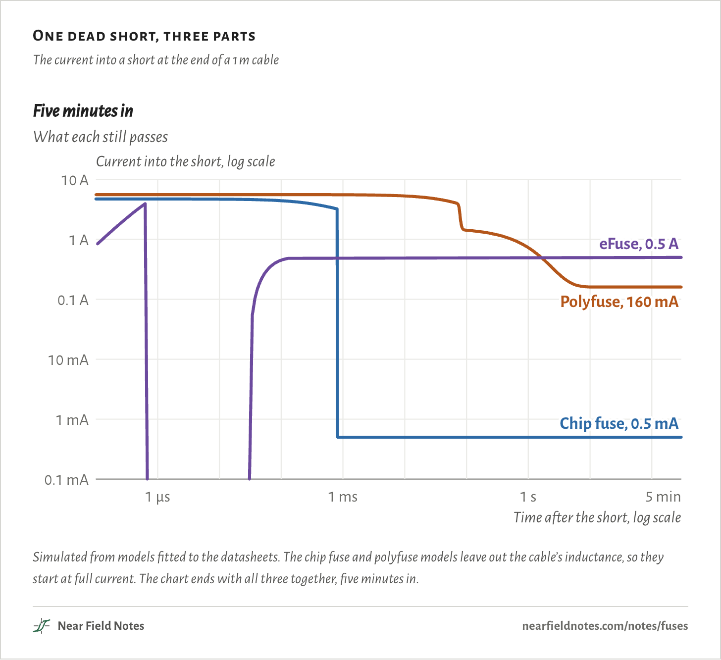
Simulated on a 5 V port rated for 0.5 A, the chip fuse opens in 0.82 ms and stays open. The polyfuse trips in 78 ms, then keeps passing 160 mA for as long as the short stays. The eFuse cuts off in 0.63 µs, then comes back on and holds up to 0.5 A until something switches it off.
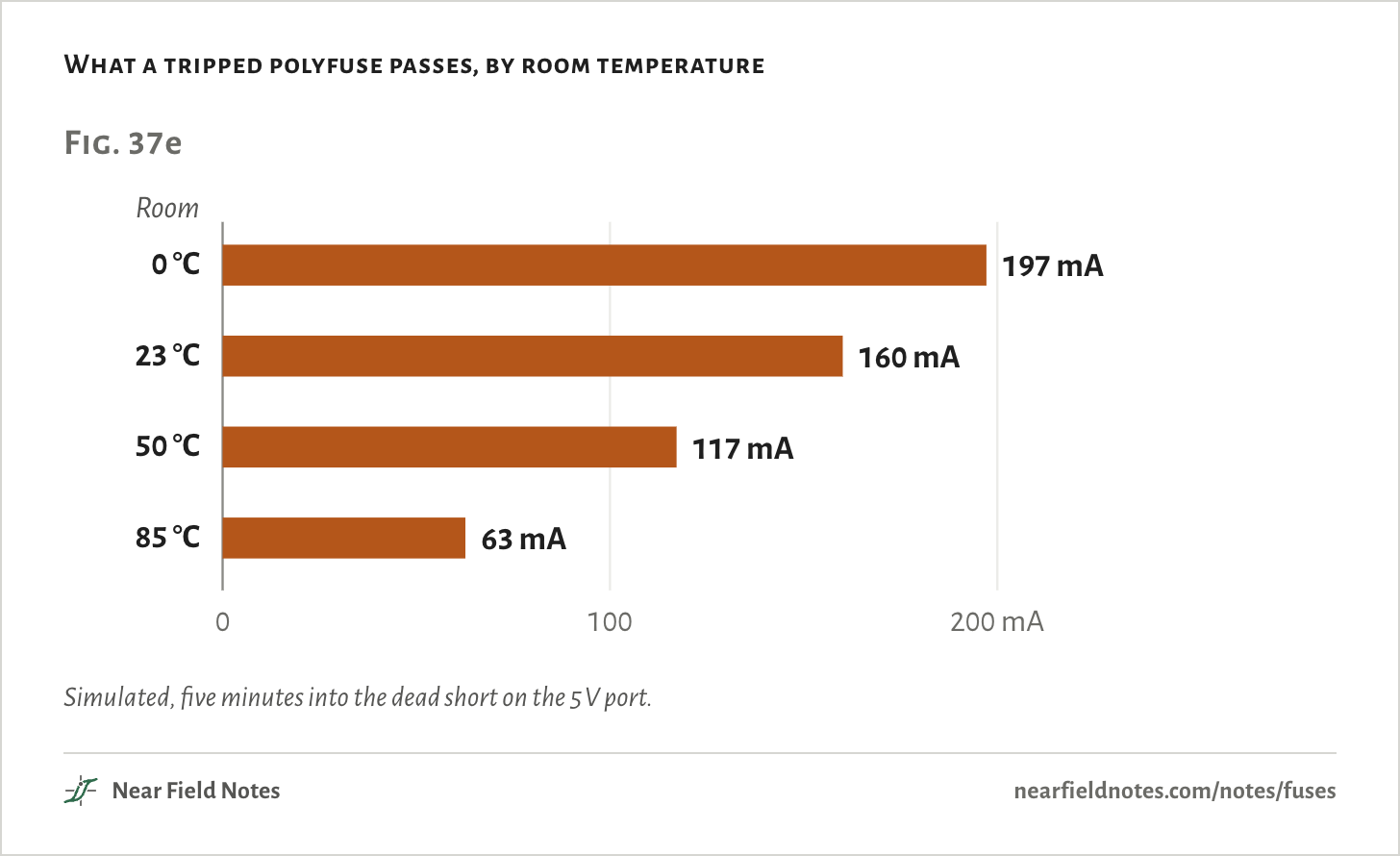
A tripped polyfuse is a heater running on the fault’s own current, and the colder the room, the more it lets through.
All three are sold as 0.5 A parts. On each one, 0.5 A means something different.
One dead short, three parts
The current into a short at the end of a 1 m cable
Simulated from models fitted to the datasheets. The chip fuse and polyfuse models leave out the cable’s inductance, so they start at full current. The chart ends with all three together, five minutes in.
A 5 V USB port, rated for 0.5 A
1 m cable, 28 AWG
Take a board with a USB-A port that it powers from its own 5 V rail. A USB 2.0 port promises a device 500 mA, and the USB spec makes the host protect its ports against over-current.
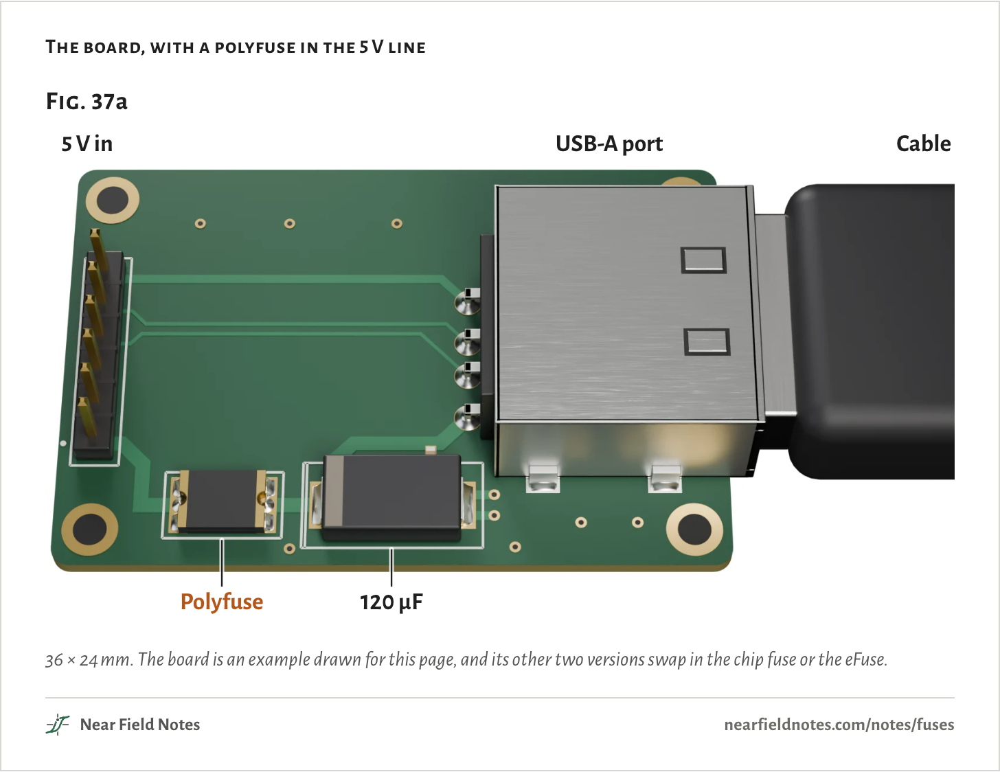
One part sits in the port’s 5 V line, between the rail and the connector. Its job is to stop a fault in whatever gets plugged in.
The board, with a polyfuse in the 5 V line
36 × 24 mm. The board is an example drawn for this page, and its other two versions swap in the chip fuse or the eFuse.
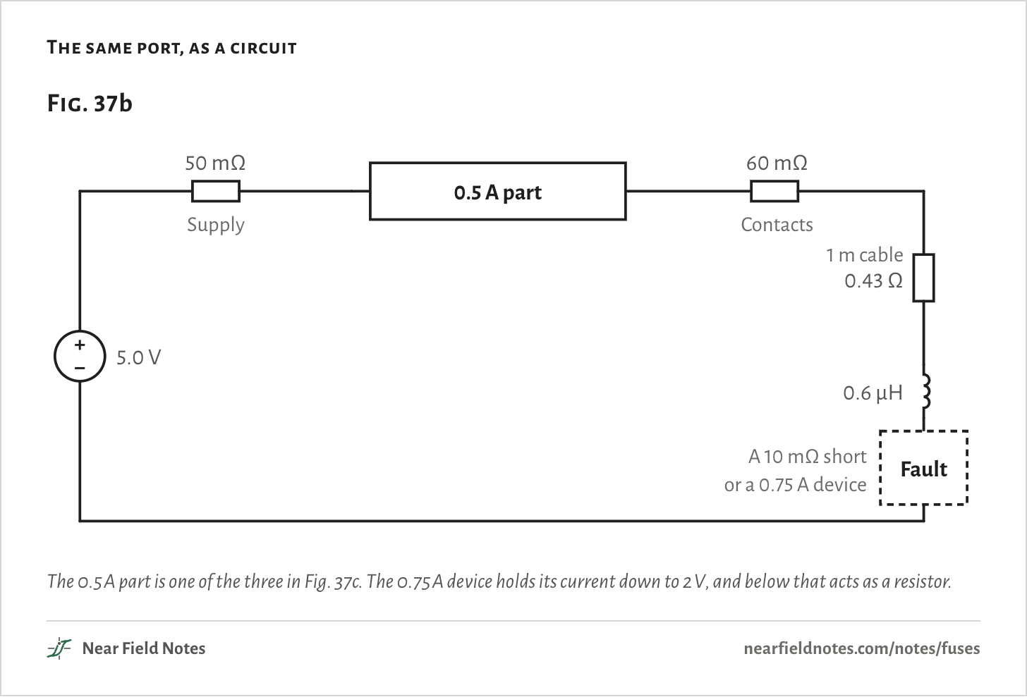
As a circuit, the rail and its copper add 50 mΩ and the port’s contacts 60 mΩ. A 1 m cable with 28 AWG power wires adds 0.43 Ω and 0.6 µH.
With nothing in the way, a dead short at the far end of the cable would draw 9.2 A.
Two faults go at that far end. One is a dead short. The other is a device that pulls 750 mA, half again what the port allows.
The same port, as a circuit
The 0.5 A part is one of the three in Fig. 37c. The 0.75 A device holds its current down to 2 V, and below that acts as a resistor.
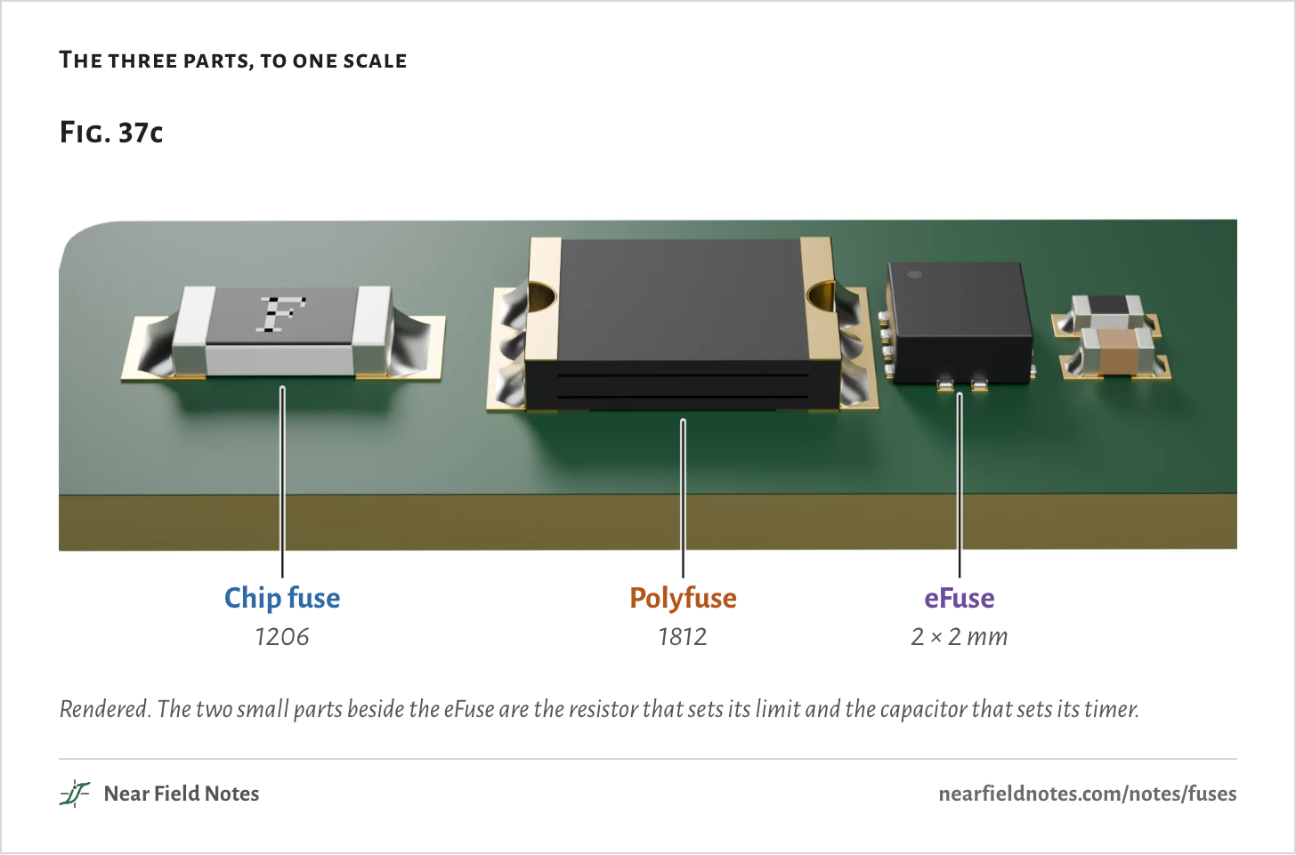
Three parts, each sold as 0.5 A
1206, 1812 and 2 × 2 mm
A chip fuse is a thin metal film on a ceramic body. Enough current melts the film, and the fuse is open for good. This one is Bourns’ SF-1206F050.
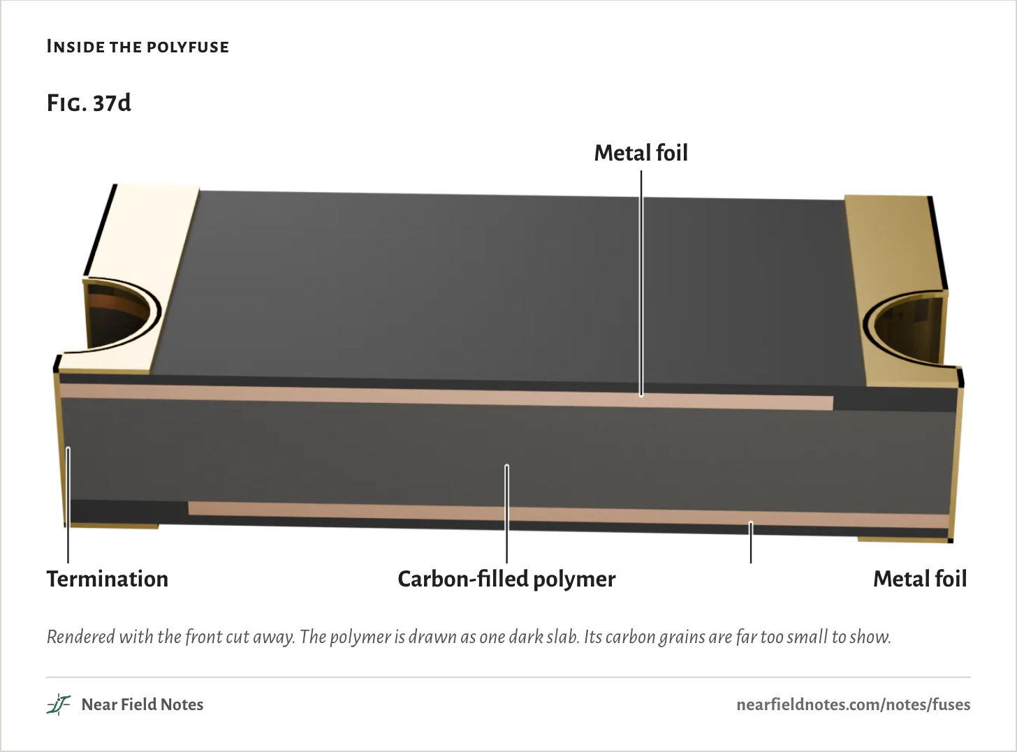
A polyfuse, or PPTC, is a slab of plastic filled with carbon, between two metal foils. It trips when it gets hot and resets when it cools. Bourns’ MF-MSMF050 is the one in the Arduino Uno’s USB power line, though Bourns now marks it not recommended for new designs.
An eFuse, short for electronic fuse, is a switch that measures its own current. One resistor sets its limit, and one capacitor sets how long it lets an overload run. TI’s TPS259474L is the latch-off version: after a long overload it switches off and stays off.
The three parts, to one scale
Rendered. The two small parts beside the eFuse are the resistor that sets its limit and the capacitor that sets its timer.The numbers
A switch that senses its current, with a timer and a temperature sensor
28 mΩ typical
Why a tripped polyfuse still conducts
160 mA at 23 °C
Cold, the carbon grains in the plastic touch one another and form chains, and current flows along them.
Near 125 °C the plastic melts and swells. The chains pull apart and the resistance climbs by decades. That is how Bel Fuse describes it, and Raychem’s guide puts the switch at 125 °C for most of its parts.
But it only stays tripped while it stays hot, and its only heat is the fault’s current flowing through it. So it settles where that current keeps it just hot enough.
Inside the polyfuse
Rendered with the front cut away. The polymer is drawn as one dark slab. Its carbon grains are far too small to show.
Bourns rates this part to give off 0.8 W once tripped, in a 23 °C room. In the simulation the tripped part settles near 123 °C and gives off 0.79 W to the board and the air.
I=PV
With the short at the far end, nearly all of the 5 V sits across the polyfuse, 4.9 V. Giving off 0.79 W at that voltage takes 160 mA. Its resistance becomes whatever makes that work, 31 Ω here.
A colder room carries more heat away, so the part has to pass more current to stay hot.
What a tripped polyfuse passes, by room temperature
Simulated, five minutes into the dead short on the 5 V port.The numbers
Five minutes into a dead short, typical part (0.35 Ω cold). From the heat model, not a bench.
Room
Current
Power in the polyfuse
Its temperature
0 °C
197 mA
0.96 W
123 °C
23 °C
160 mA
0.79 W
123 °C
50 °C
117 mA
0.58 W
124 °C
85 °C
63 mA
0.31 W
125 °C
624
Tripped polyfuse
160 mA for as long as the short stays
Field marks. Five minutes into a dead short the port still delivers 160 mA. The polyfuse sits near 123 °C and gives off 0.79 W, for as long as the short and the supply last.
Look-alike. An open fuse. Nothing past it works, and the fault looks cleared. But current still flows, and the part stays hot.
Range. The room matters more than the part: 197 mA at 0 °C, 117 mA at 50 °C and 63 mA at 85 °C. A part at its lowest or highest resistance passes 158 to 162 mA.
Habitat. USB ports on development boards and computers, and other low-voltage rails. This one is rated for 15 V at most.
625
A dead short at the end of the cable
9.2 A with nothing in the way
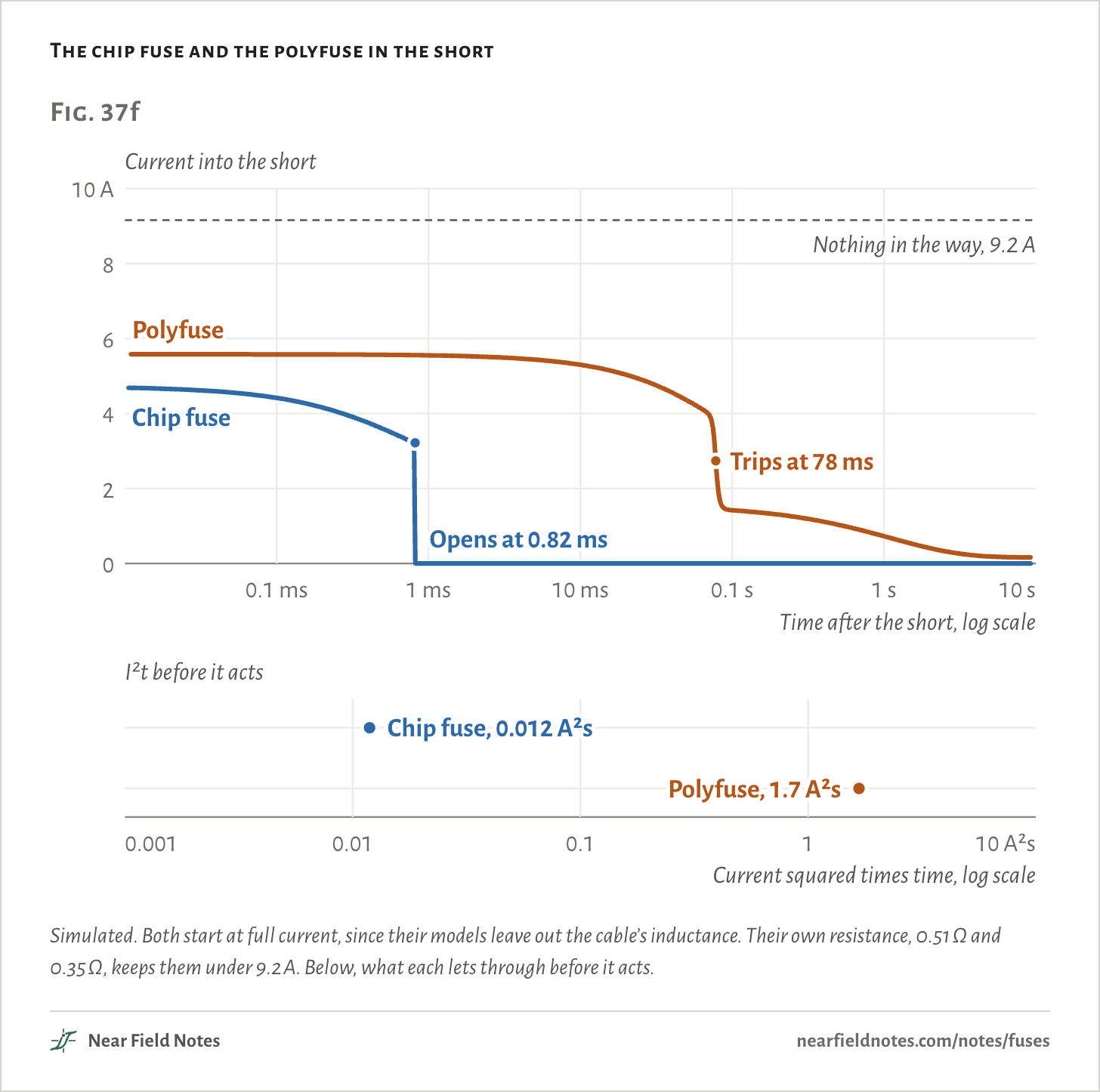
The chip fuse carries 4.7 A and opens in 0.82 ms. Bourns says it then measures at least 10 kΩ, so at most 0.5 mA gets through.
The polyfuse carries 5.6 A and takes 78 ms to trip, then settles to 160 mA over the next few seconds.
That is a little more current for 95 times as long. So before it trips, the polyfuse lets through 141 times the chip fuse’s I²t, the current squared over time that heats the cable and the copper.
The chip fuse and the polyfuse in the short
Simulated. Both start at full current, since their models leave out the cable’s inductance. Their own resistance, 0.51 Ω and 0.35 Ω, keeps them under 9.2 A. Below, what each lets through before it acts.The numbers
Both models start at full current: they leave out the cable’s inductance.
Part
Current at first
Acts at
Current then
I²t until then
Current at 10 s
Chip fuse
4.72 A
0.82 ms
3.22 A
0.01187 A²s
0.5 mA
Polyfuse
5.58 A
78 ms
2.74 A
1.672 A²s
161.3 mA
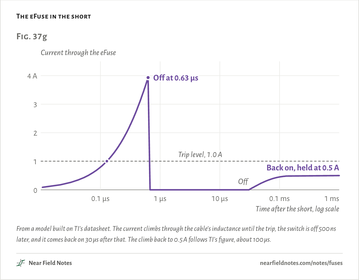
The eFuse watches its current. It reaches the trip level, twice its limit, 128 ns into the short, and its switch is off 0.63 µs in.
Then the eFuse turns itself back on. TI’s design waits 30 µs and switches on again in current limit, so the port recovers quickly if the fault was brief.
If the short is still there, it stays in current limit. TI’s table of faults lists a short as “Circuit Breaker followed by Current Limit”, not as one that latches off.
In the simulation it holds 0.5 A. TI says the limit drops lower when the output is under 1.9 V, without giving a number, and here the output sits near 0.25 V. So 0.5 A is the most it passes.
The eFuse in the short
From a model built on TI’s datasheet. The current climbs through the cable’s inductance until the trip, the switch is off 500 ns later, and it comes back on 30 µs after that. The climb back to 0.5 A follows TI’s figure, about 100 µs.
Holding 0.5 A with nearly all of the 5 V across it puts 2.4 W into a 2 × 2 mm package.
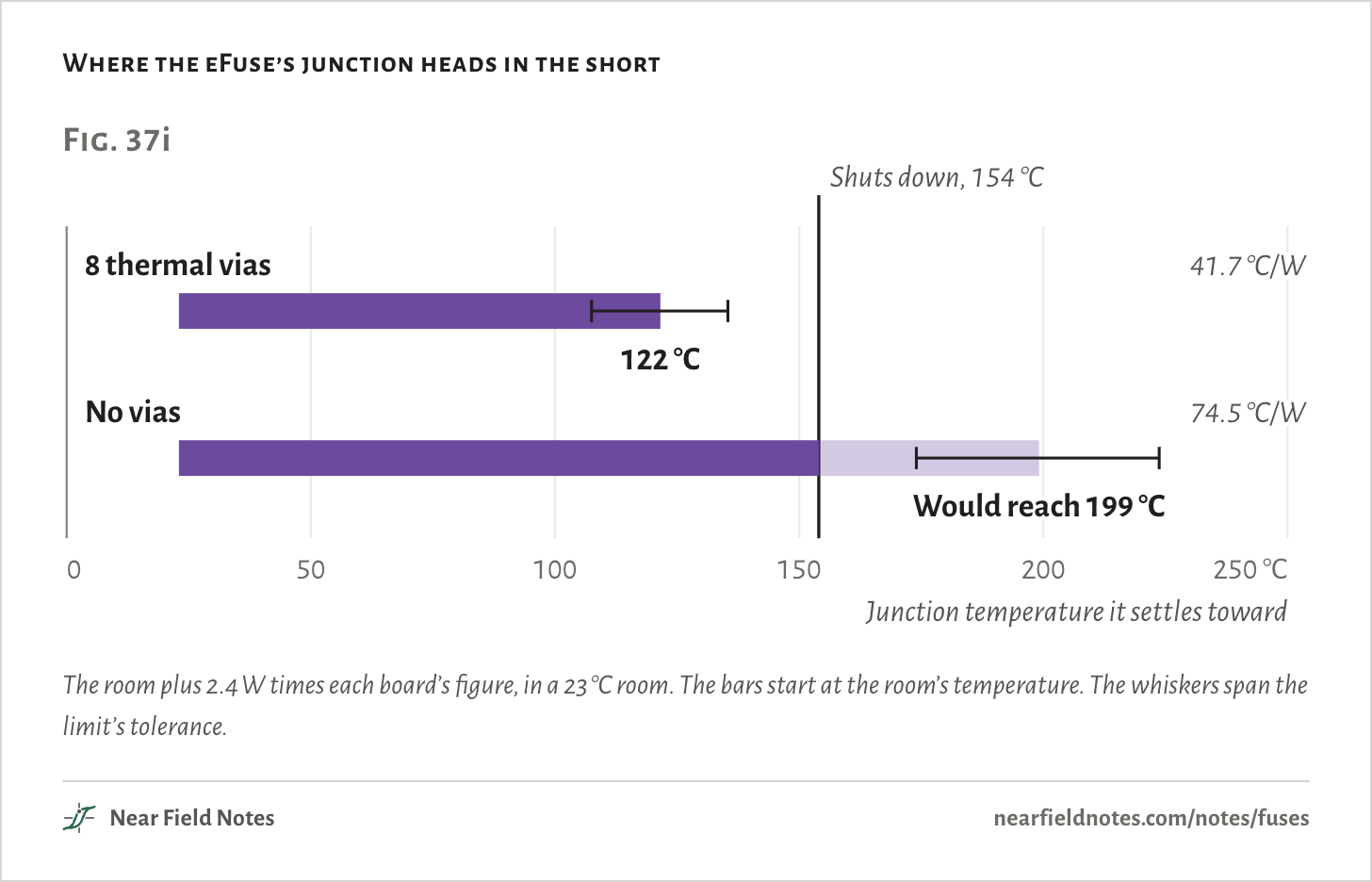
The eFuse shuts itself down at 154 °C. How hot it gets depends on the board around it. TI gives two figures: 41.7 °C/W on a four-layer board with eight thermal vias under the part, and 74.5 °C/W on one with none.
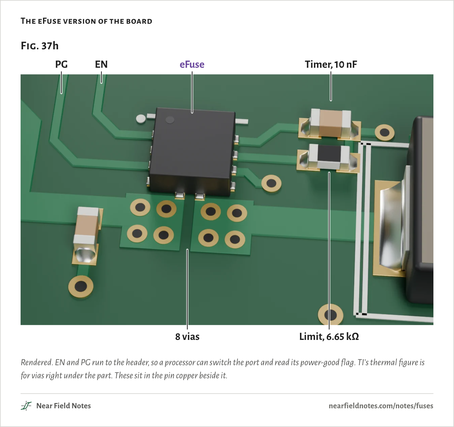
The board here puts eight vias in the copper at the eFuse’s input and output pins.
The eFuse version of the board
Rendered. EN and PG run to the header, so a processor can switch the port and read its power-good flag. TI’s thermal figure is for vias right under the part. These sit in the pin copper beside it.
Where the eFuse’s junction heads in the short
The room plus 2.4 W times each board’s figure, in a 23 °C room. The bars start at the room’s temperature. The whiskers span the limit’s tolerance.The numbers
Room 23 °C. Power in the eFuse is the limit times the voltage left across it: 2.03, 2.36 and 2.69 W. Both boards are TI’s, from its datasheet’s thermal table.
Board
Junction to room
Limit 0.425 A
0.500 A
0.575 A
8 thermal vias
41.7 °C/W
108 °C
122 °C
135 °C
No vias
74.5 °C/W
174 °C
199 °C
224 °C
626
eFuse in a short
122 °C, short of its 154 °C shutdown
Field marks. With the eight vias it settles at 122 °C. It stays on, passing up to 0.5 A into the short, until something switches it off.
Look-alike. A part that has done its job. Nothing past it works, but it is still giving off up to 2.4 W.
Range. Across its limit’s tolerance, 0.425 A to 0.575 A, it settles at 108 °C to 135 °C. The top of that is past the 125 °C TI characterizes it to. At the typical limit it would reach shutdown only in a room above 55 °C.
Habitat. Without the vias it heads for 199 °C, so it reaches 154 °C and shuts down, and this version stays off until EN or the power is cycled. The better the board cools it, the longer it holds the short.
627
Holding 0.5 A into the short is no more than the port may deliver to a working device, so the cable and whatever shorted are not overstressed. The cost is the eFuse’s heat, and the rail, or a battery, feeding a dead port for as long as the short lasts.
So in a dead short it needs something else to switch it off. The auto-retry version, the TPS259474A, would hold on the same way. It differs only after a shutdown, and with the vias there is none.
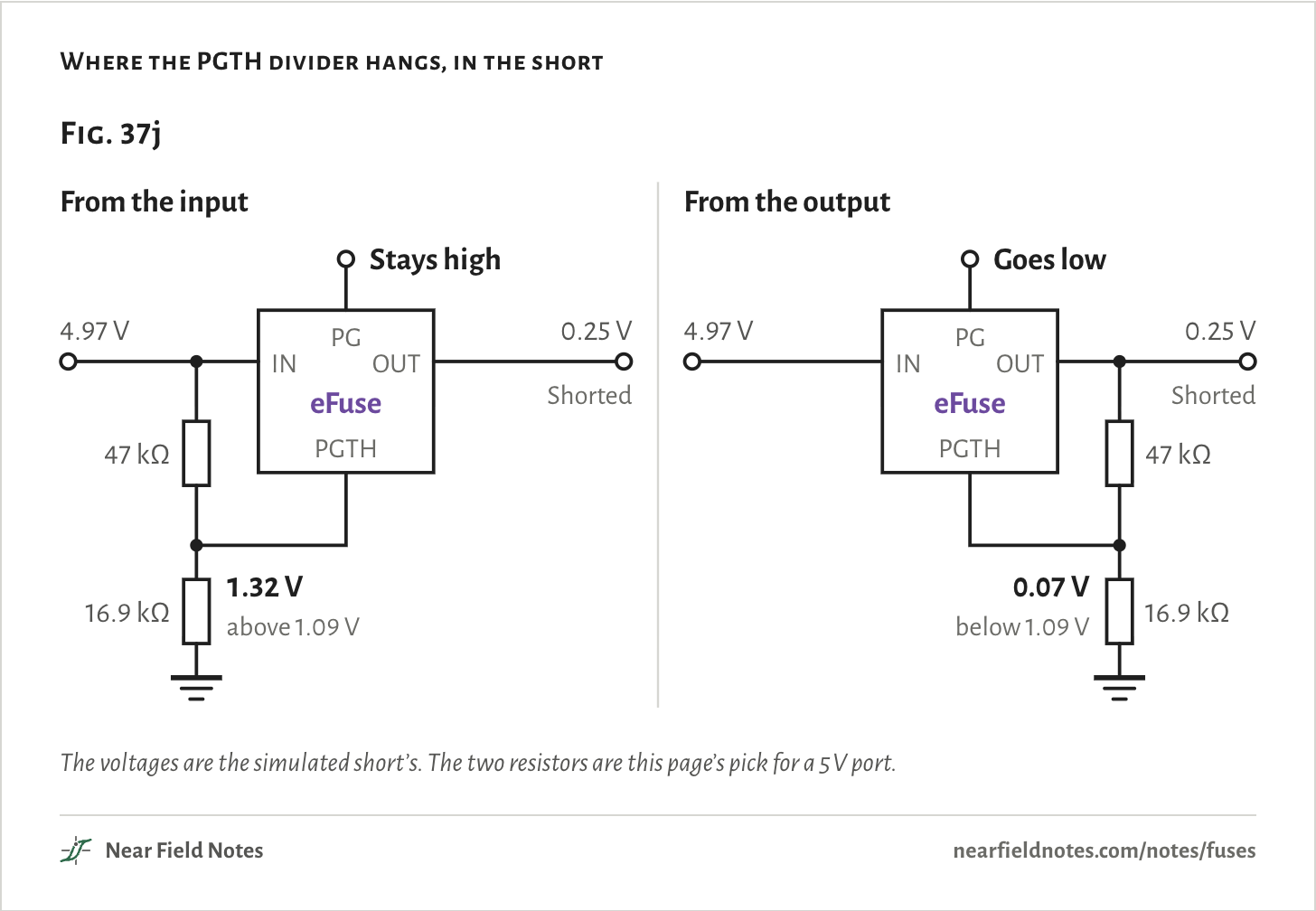
That something is usually a processor reading the eFuse’s PG pin. TI says PG goes low for faults “except overcurrent”, and in a short it follows only the voltage on the PGTH pin, set by two resistors.
TI lets that divider hang from the input or the output. From the input, it never sees the short, so the firmware never hears about it.
From the output, as in TI’s example circuit, a healthy port puts 1.32 V on PGTH, past the 1.20 V that raises PG. In the short PG drops, and the processor can pull EN low to switch the port off.
Where the PGTH divider hangs, in the short
The voltages are the simulated short’s. The two resistors are this page’s pick for a 5 V port.The numbers
TI’s typical thresholds: PG rises past 1.20 V on PGTH and falls below 1.09 V. The divider is 47 kΩ over 16.9 kΩ, picked for this 5 V port.
Divider from
PGTH, port healthy
PGTH, port shorted
PG in the short
Input
1.32 V
1.32 V
Stays high
Output
1.32 V
0.07 V
Goes low
A 750 mA device
Half again the port’s 500 mA
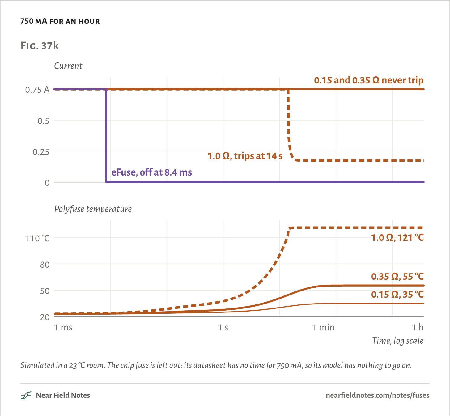
The eFuse lets it run for 8.4 ms: the time its timer current, 1.8 µA, takes to pull 1.51 V off the 10 nF capacitor, and 2 µs more to open. Then the TPS259474L switches off and stays off until EN or the power is cycled. The auto-retry version, the TPS259474A, would instead try again 110 ms after each trip.
The polyfuse sits between its hold current, 0.5 A, and its trip current, 1.0 A, where it may do either. Its resistance decides. Bourns allows 0.15 Ω new and up to 1.0 Ω an hour after a trip or soldering, and this page takes 0.35 Ω between them.
A part at 0.15 or 0.35 Ω warms to 35 °C or 55 °C and carries the device for the whole hour. One at its 1.0 Ω limit trips at 14 s and then passes 174 mA.
A warm room tips it. At 40 °C the 1.0 Ω part trips at 8.9 s, and at 60 °C the 0.35 Ω part still holds on, at 110 °C.
Bourns’ curve for the chip fuse stops at 0.95 A, 100 s. The part meets UL 248-14, under which a fuse must open within an hour at 135% of its rating, 0.675 A here. So at 750 mA it opens within the hour, and the datasheet gives no closer time.
750 mA for an hour
Simulated in a 23 °C room. The chip fuse is left out: its datasheet has no time for 750 mA, so its model has nothing to go on.The numbers
A 750 mA device for an hour. The polyfuse’s resistance is its cold value, before any trip.
Part
Trips
Current after an hour
Polyfuse temperature after an hour
0.15 Ω, room 23 °C
never
750 mA
35 °C
0.35 Ω, room 23 °C
never
750 mA
55 °C
1.0 Ω, room 23 °C
14 s
174 mA
121 °C
0.35 Ω, room 40 °C
never
750 mA
79 °C
0.35 Ω, room 50 °C
never
750 mA
94 °C
0.35 Ω, room 60 °C
never
750 mA
110 °C
1.0 Ω, room 40 °C
8.9 s
141 mA
122 °C
eFuse, any room
8.4 ms
0
–
What 0.5 A means on each part
Three different promises
On the chip fuse, 0.5 A is a test point. Bourns’ part carries it for at least 4 hours and opens within a minute at twice that. Fuse makers advise running one at no more than 75% of its rating at room temperature, 0.375 A here.
On the polyfuse, it is the hold current: what the part is sure to carry at 23 °C without tripping. It is sure to trip only at 1.0 A.
On the eFuse, it is a set point. A 6.65 kΩ resistor sets it, and TI’s table gives 0.425 A to 0.575 A for any junction from −40 to 125 °C.
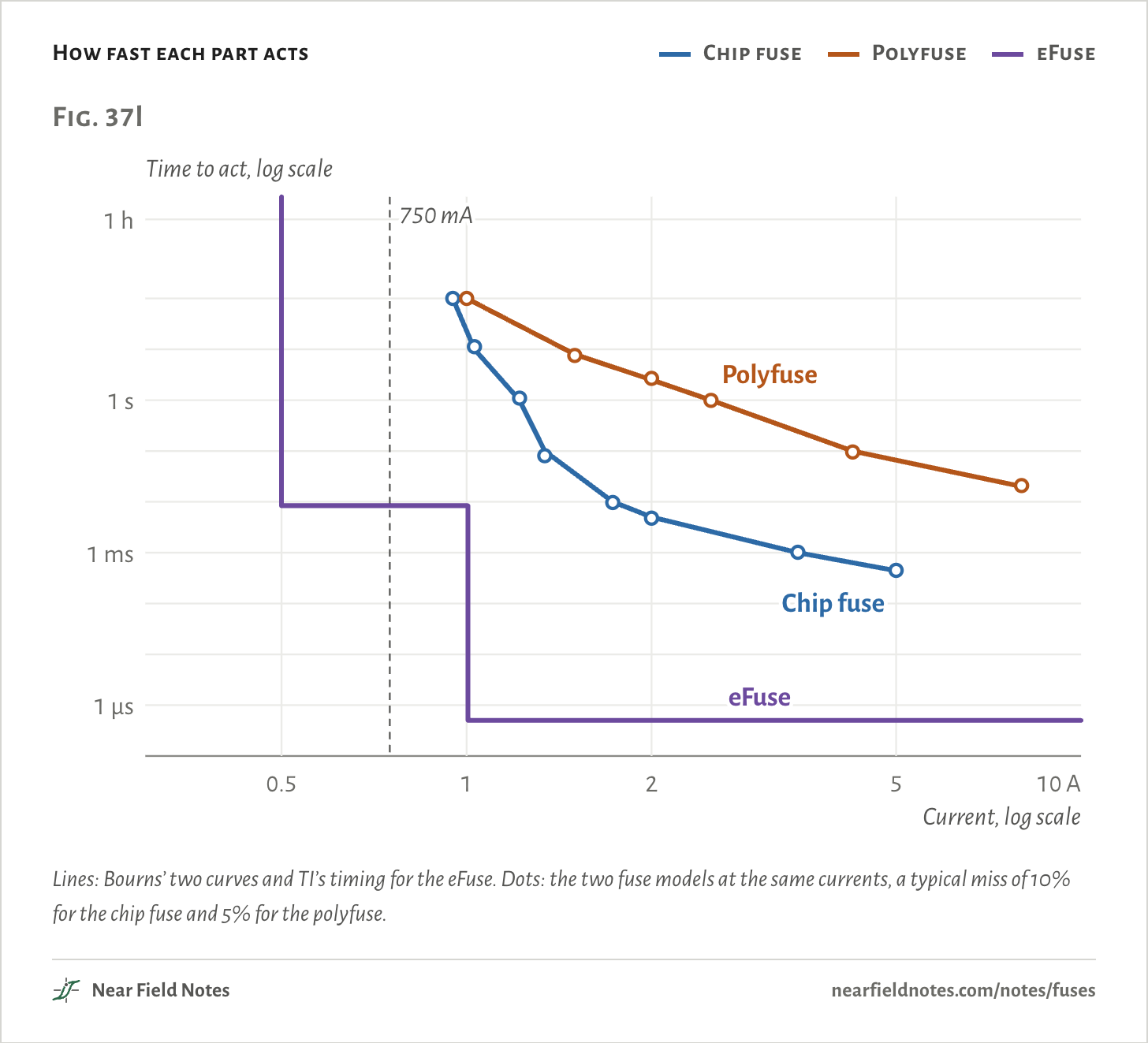
Near their rating the chip fuse and the polyfuse take seconds to minutes. The eFuse takes 8.4 ms anywhere between its limit and twice its limit, and half a microsecond above that.
At 1 A, twice the rating, the chip fuse opens in 16 s and the polyfuse trips in 100 s. Higher up, the chip fuse pulls far ahead.
How fast each part acts
Chip fuse
Polyfuse
eFuse
Lines: Bourns’ two curves and TI’s timing for the eFuse. Dots: the two fuse models at the same currents, a typical miss of 10% for the chip fuse and 5% for the polyfuse.The numbers
The chip fuse’s times are Bourns’ average melting times; the polyfuse’s, its typical times to trip at 23 °C, for a part of 0.35 Ω. Both read off the datasheets’ graphs.
Part
Current
Datasheet
Heat model
Chip fuse
5 A
0.44 ms
0.45 ms
Chip fuse
3.46 A
1 ms
1 ms
Chip fuse
2 A
5 ms
4.8 ms
Chip fuse
1.73 A
10 ms
9.7 ms
Chip fuse
1.34 A
100 ms
81 ms
Chip fuse
1.22 A
1 s
1.1 s
Chip fuse
1.03 A
10 s
11 s
Chip fuse
0.95 A
100 s
100 s
Polyfuse
1 A
100 s
100 s
Polyfuse
1.5 A
8 s
7.6 s
Polyfuse
2 A
2.5 s
2.7 s
Polyfuse
2.5 A
1 s
0.99 s
Polyfuse
4.25 A
100 ms
96 ms
Polyfuse
8 A
20 ms
21 ms
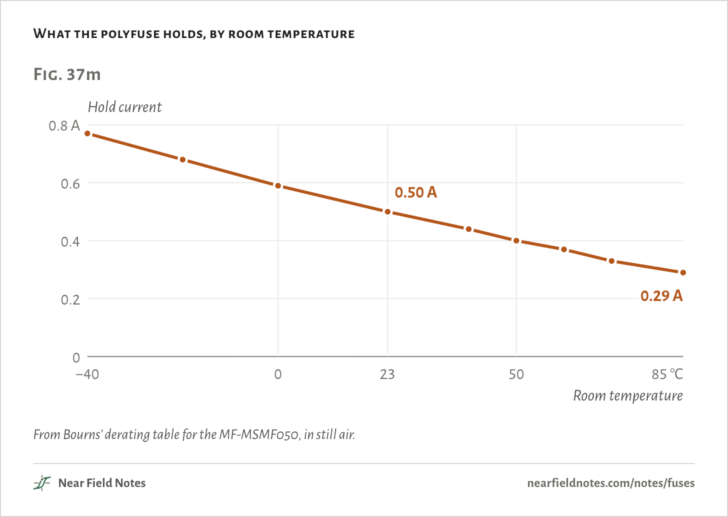
Heat moves the polyfuse’s rating most. It trips by getting hot, so a warm room leaves it less to do. At 85 °C it holds only 0.29 A, where Bourns’ curve takes the chip fuse to 0.46 A.
Its resistance also costs voltage. At 0.5 A a part at 1.0 Ω loses 0.5 V from the port. The chip fuse, at Bourns’ typical 0.517 Ω, loses 0.26 V, and the eFuse 14 mV.
The chip fuse has one more number that counts: it can interrupt 50 A at 63 V. Past that it isn’t rated to clear safely.
What the polyfuse holds, by room temperature
From Bourns’ derating table for the MF-MSMF050, in still air.The numbers
The model’s column is the most a part at its 1.0 Ω limit carries for 30 minutes without tripping, the datasheet’s hold test. It runs above Bourns’ table, by 0.01 to 0.09 A.
Room
Hold, Bourns
Heat model, 1.0 Ω part
−40 °C
0.77 A
0.78 A
−20 °C
0.68 A
0.72 A
0 °C
0.59 A
0.66 A
23 °C
0.50 A
0.59 A
40 °C
0.44 A
0.53 A
50 °C
0.40 A
0.49 A
60 °C
0.37 A
0.45 A
70 °C
0.33 A
0.40 A
85 °C
0.29 A
0.32 A
Side by side
The same port, the same faults
Three 0.5 A parts on a 5 V port
Fig. 37n
Chip fuse
Polyfuse
eFuse
What 0.5 A means
Carries it 4 hours; opens within 60 s at 1 A
Holds it at 23 °C; sure to trip at 1 A
Its limit, set by one resistor: 0.425 to 0.575 A
Voltage lost at 0.5 A
0.26 V typical; 0.19 to 0.32 V within ±25%
75 mV new at 0.15 Ω, up to 0.5 V after a trip
14 mV typical, 22.5 mV at most
Dead short
Opens in 0.82 ms
Trips in 78 ms
Off in 0.63 µs
After the short
0.5 mA at most, for good
160 mA while the short stays
Up to 0.5 A until switched off
750 mA device
No published time; within an hour under UL 248-14
Trips at 14 s at 1.0 Ω; never at 0.15 or 0.35 Ω
Off at 8.4 ms, stays off
Resets
No: replace it
Itself, once the fault is gone and it cools
On a toggle of EN or power
Tells anyone
No
No
PG goes low, if PGTH hangs from the output
Most voltage
63 V
15 V
23 V
Its 0.5 A in an 85 °C room
0.46 A, 91% on Bourns’ curve
0.29 A held
0.425 to 0.575 A, TI’s limits for any junction from −40 to 125 °C
From the simulations above and the three datasheets. The eFuse’s PG pin reports a short only if its PGTH divider hangs from the output, as in Fig. 37j.
Which part where?
Two questions
The choice comes down to whether a fault must stay cut, and whether anything is watching the port.
Key to protecting a 5 V output
Which part goes in the line?
1aThe fault must stay cut, as at a battery or a supply that can deliver far more than the wiring can carryChip fuse, rated to interrupt it
1bA USB host port, or an output that should come back by itselfGo to 2
2aA processor can watch iteFuse, PG to the processor, PGTH from the output
2bNothing watches itPolyfuse, sized for the warmest room
USB 2.0 asks a host’s protection to remove or reduce power and to reset without anyone touching it, and names polymeric PTCs and solid-state switches as examples. That leaves a chip fuse out of a host port. On the latch-off TPS259474L, that reset is firmware toggling EN. The TPS259474A retries by itself. The board in Fig. 37a ends at 2b, and its eFuse version in Fig. 37h at 2a.
Conditions
Simulated
Every current, time and temperature on this page comes from models fitted to the parts’ datasheets. None was measured on a bench.
Port
A stiff 5.0 V rail, 50 mΩ of source and board copper, 60 mΩ of port and plug contacts, and a 1 m cable with 28 AWG power wires: 0.213 Ω per meter each way and 0.6 µH. Room 23 °C unless a figure says otherwise.
Faults
A 10 mΩ short at the cable’s far end, run for 5 minutes. A device drawing 0.75 A that acts as a resistor once its voltage falls below 2 V, run for an hour.
Chip fuse
Bourns SF-1206F050. A heat model with three steps, the film and two layers of body, fitted to Bourns’ average melting times from 0.44 ms at 5 A to 100 s at 0.95 A. It opens when the film reaches a set temperature. Its I²t at 5 A comes out at 0.0112 A²s, against Bourns’ 0.011 A²s. Once open it is 10 kΩ, the least Bourns allows.
Polyfuse
Bourns MF-MSMF050. A heat model with two steps, the part and the board under it, and a resistance that climbs slowly and then by decades past 118 °C. Fitted to Bourns’ typical trip times, from 100 s at 1 A to 20 ms at 8 A, and to its 0.8 W tripped, taken at 125 °C. Cold, 0.35 Ω unless a figure says 0.15 or 1.0 Ω.
eFuse
TI TPS259474L with 6.65 kΩ on its ILM pin and 10 nF on ITIMER. A model of its events from TI’s datasheet: a trip at 2.01 times the limit, off 500 ns later, and back on in current limit 30 µs after that. Between the limit and twice it, the timer runs out after 1.51 V at 1.8 µA, then 2 µs to open. Its junction is the room plus the power times TI’s figure for the board.
Render
Blender. The board is an example drawn for this page.
Fitted to datasheets. Nothing on this page has been measured on a bench.
Limits
Bourns gives no typical resistance for the polyfuse, so 0.35 Ω is an assumption between its 0.15 Ω minimum and 1.0 Ω maximum. In the short it hardly matters: 158 to 162 mA across that range.
Below 1.9 V on its output, TI says the eFuse’s limit drops lower, without a number. The page holds it at 0.5 A, so its 0.5 A and 2.4 W in the short are the most they could be.
The voltages lost at 0.5 A use the datasheets’ resistances, which Bourns measures cold. Both fuses run warmer at 0.5 A and read a little higher.
The chip fuse’s model has no data below 0.95 A, where Bourns’ curve stops. Its 750 mA case rests on UL 248-14 alone.
The chip fuse and polyfuse models are resistors, with no cable inductance. In their first microsecond the real current would still be climbing, as the eFuse’s does.
The eFuse’s temperatures use TI’s two board figures, which TI simulated for its own boards. A real board will differ, and so will vias beside the part rather than under it.
Near the hold current the polyfuse model is least sure. Bourns’ hold table sits 0.01 to 0.09 A under the model’s 1.0 Ω part, so a real part could trip in the 750 mA case where the model’s doesn’t.
Bourns marks the MF-MSMF050 not recommended for new designs. Its 16 V version, the MF-MSMF050/16X, can measure up to 1.3 Ω after a trip.
Files
sim/fuses.pyThe port, both heat models and their fits, the eFuse’s events and every fault
render/scene.pyThe board and the three parts in Blender