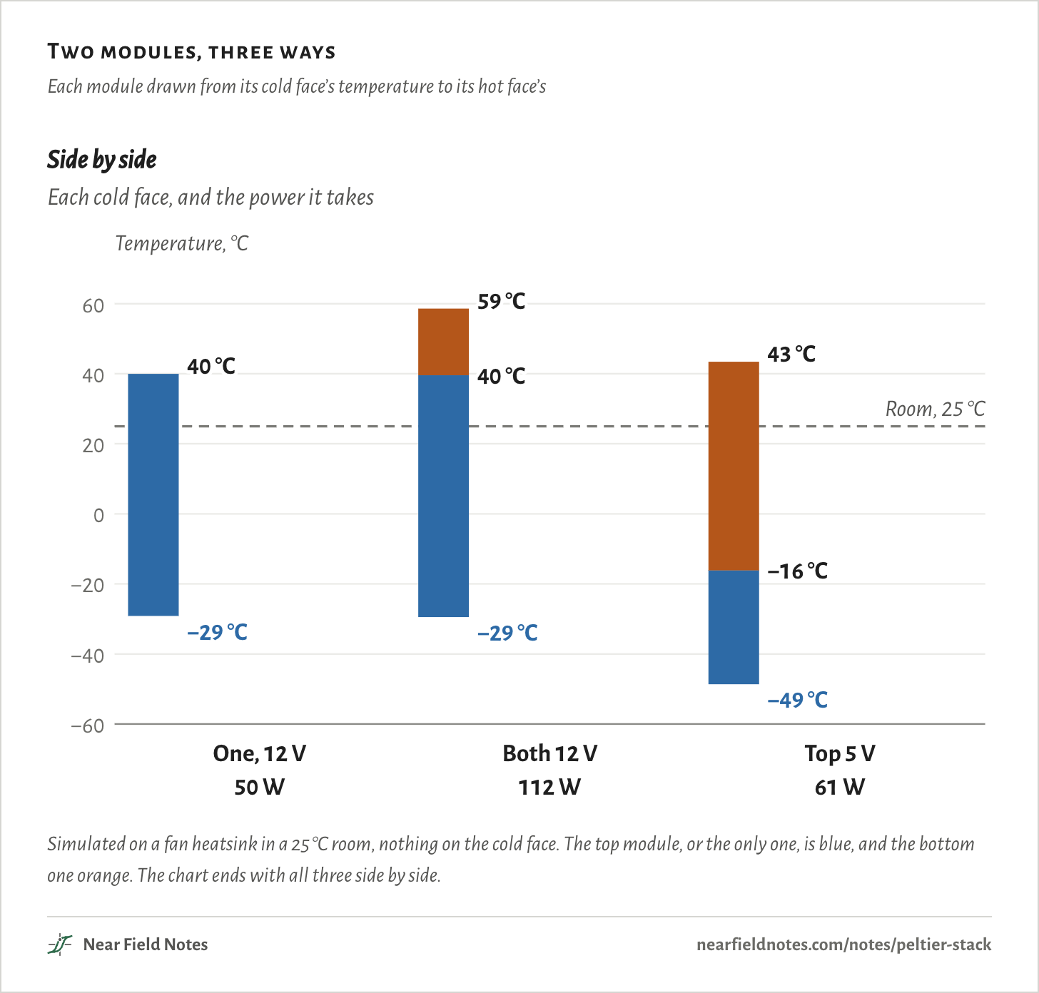
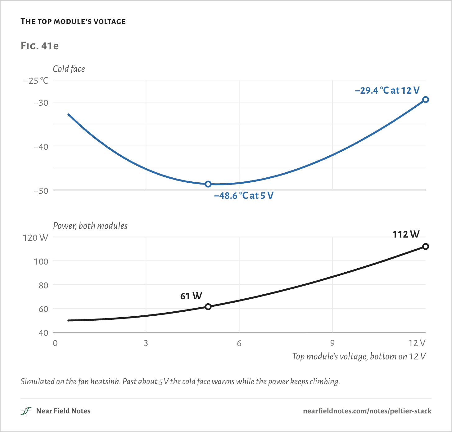
Not at the same voltage. Simulated on a fan heatsink, one TEC1-12706 at 12 V takes its cold face to −29.2 °C. Stack a second one on top, each wired straight to 12 V, and the cold face reaches −29.4 °C, on 112 W instead of 50 W. Run the top one at 5 V and the pair reaches −48.6 °C on 61 W.
The bottom module has to carry all the heat the top one burns. At 12 V that keeps the joint between them at 39.6 °C, warmer than the room.
A stack pays off when each stage is weaker than the one under it: a lower voltage on the top module, or fewer legs in a factory part.
Two modules, three ways
Each module drawn from its cold face’s temperature to its hot face’s
Simulated on a fan heatsink in a 25 °C room, nothing on the cold face. The top module, or the only one, is blue, and the bottom one orange. The chart ends with all three side by side.
Two TEC1-12706s on a fan heatsink
40 mm, 127 pairs of legs
The TEC1-12706 is the common 40 mm Peltier module: 127 pairs of bismuth telluride legs between two ceramic faces. Current through the legs carries heat from one face to the other. Note 39 shows how one works and how to drive it.
Here one sits on a fan heatsink that warms 0.30 °C for every watt it takes, in a 25 °C room. Nothing sits on its cold face and no air reaches it, so each number is the coldest the setup can get.
Then a second, identical module goes on top of the first, with a film of grease between them, each on its own supply.
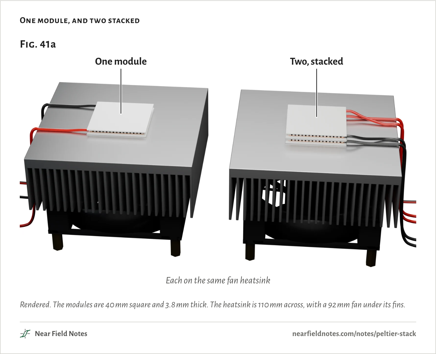
One module, and two stacked
Rendered. The modules are 40 mm square and 3.8 mm thick. The heatsink is 110 mm across, with a 92 mm fan under its fins.
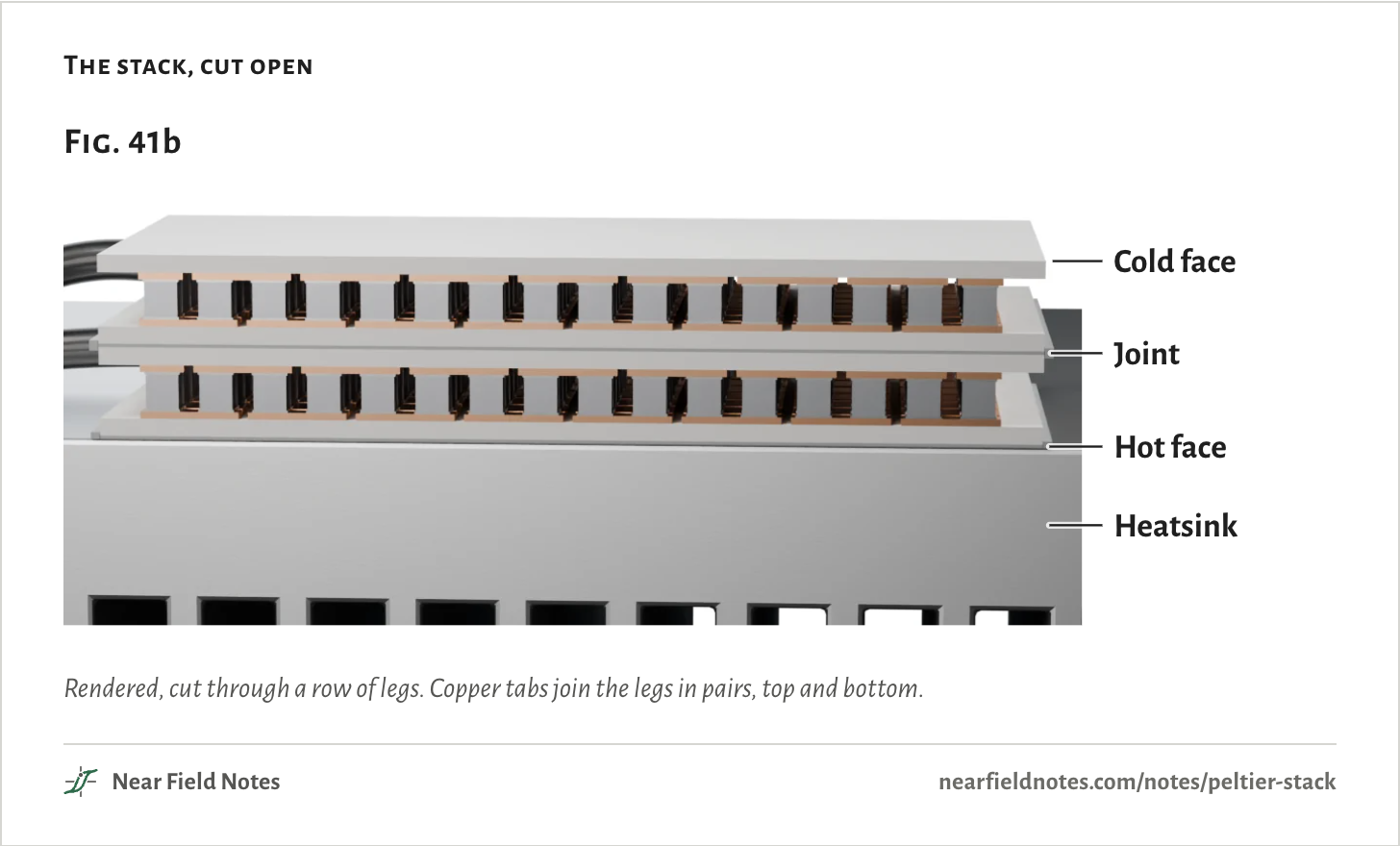
Stacked, the pair has three faces that matter: the top module’s cold face, the joint where the two meet, and the bottom module’s hot face on the heatsink.
Each module is one stage of the stack. The top one cools the cold face, and the bottom one cools the top one.
The stack, cut open
Rendered, cut through a row of legs. Copper tabs join the legs in pairs, top and bottom.
Why a second module on 12 V adds nothing
Joint at 39.6 °C
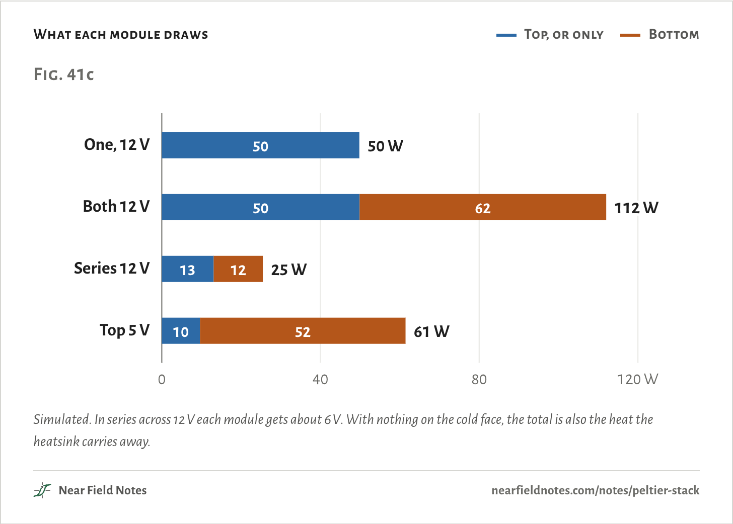
At 12 V the top module draws 49.9 W. All of it, plus whatever it pulls off its cold face, lands on the bottom module.
So the bottom module is busy just keeping up. It draws 62.2 W carrying that heat down to the heatsink, and the joint settles at 39.6 °C, warmer than the room.
The top module works down from there. Its 69.0 °C drop gets the cold face only back to −29.4 °C. One module alone, its hot face on the heatsink at 39.9 °C, already got to −29.2 °C.
What each module draws
Top, or only
Bottom
Simulated. In series across 12 V each module gets about 6 V. With nothing on the cold face, the total is also the heat the heatsink carries away.The numbers
On the fan heatsink, 25 °C room, nothing on the cold face. From the model, not a bench.
Case
Top (or only) module
Bottom module
In all
Cold face
On the heatsink
One module, 12 V
12 V, 4.15 A, 49.8 W
None
49.8 W
−29.2 °C
39.9 °C
Two stacked, each on 12 V
12 V, 4.16 A, 49.9 W
12 V, 5.18 A, 62.2 W
112.0 W
−29.4 °C
58.6 °C
Two stacked, in series across 12 V
6.2 V, 2.12 A, 13.1 W
5.8 V, 2.12 A, 12.4 W
25.5 W
−34.8 °C
32.6 °C
Top 5 V, bottom 12 V
5 V, 1.93 A, 9.6 W
12 V, 4.32 A, 51.8 W
61.5 W
−48.6 °C
43.4 °C
660
Two modules, each on 12 V
−29.4 °C on 112 W
Field marks. The cold face sits within a few tenths of a degree of one module’s, on more than twice the power. The joint is warmer than the room, and the face on the heatsink reaches 58.6 °C.
Look-alike. The same two wired in series across 12 V: −34.8 °C on 25 W, 5.6 °C colder than one module.
Range. Let room air reach the cold face and both warm a little, to −27.7 °C for one module and −27.2 °C for the pair. The gap stays under a degree.
Habitat. Stacks built by hand from two of the same module, each wired straight across one 12 V supply.
661
Two in series on one 12 V supply
−34.8 °C on 25 W
Wire the same two in series across one 12 V supply and the pair reaches −34.8 °C on 25 W. That is 5.6 °C colder than one module at 12 V, on about half the power. It is still far short of the −48.6 °C the pair reaches with its top on 5 V.
In series the two carry one current, so they act as one module with legs twice as tall. Each gets about 6 V, so the pair draws less, and the heatsink runs cooler: 32.6 °C against 39.9 °C under one module at 12 V.
So the gain is the heatsink’s, not the stack’s. Hold the hot face at 27 °C, the way datasheets rate modules, and it shrinks to under a degree: at their best currents one module bottoms out at −43.5 °C, the pair at −44.4 °C and a module with legs twice as tall at −43.5 °C.
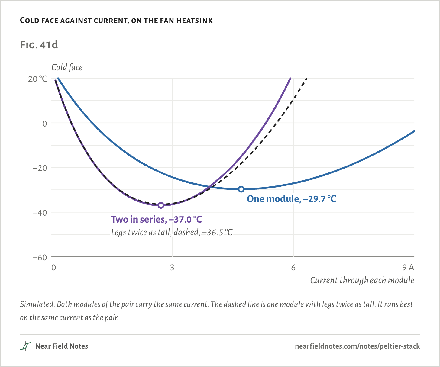
Back on the fan heatsink, at their best currents, the pair reaches −37.0 °C against −29.7 °C for one module, on 40 W against 63 W. One module with legs twice as tall gets −36.5 °C, nearly the same.
A correction to the video: it says the pair in series is no colder than one module. That is within a degree of true with the hot face fixed at 27 °C. On the video’s own fan heatsink the pair is 5.6 °C colder, as above.
Cold face against current, on the fan heatsink
Simulated. Both modules of the pair carry the same current. The dashed line is one module with legs twice as tall. It runs best on the same current as the pair.The numbers
Each at its own best current. Fan: the fan heatsink in a 25 °C room. Held 27 °C: the hot face held at 27 °C, as datasheets rate modules. From the model, not a bench.
Stack
Fan: coldest
at
drawing
Held 27 °C: coldest
at
drawing
One module
−29.7 °C
4.71 A
63.0 W
−43.5 °C
6.46 A
103.9 W
Two in series
−37.0 °C
2.72 A
40.0 W
−44.4 °C
3.21 A
52.4 W
One, legs twice as tall
−36.5 °C
2.73 A
40.0 W
−43.5 °C
3.23 A
51.9 W
The top stage has to be the weak one
Top at 5 V
The fix is to make the top module the weak one. On 5 V it draws only 9.6 W, so the bottom module has little to carry and pulls the joint down to −16.1 °C.
From there the top module’s own drop reaches −48.6 °C, 19.5 °C colder than one module, on 61 W in all.
Sweep the top module’s voltage with the bottom on 12 V, and the cold face bottoms out at −48.7 °C at 5.25 V. So 5 V is about as good as it gets.
Higher, the top burns more than it lifts. At 8 V the joint is back above freezing, at 3.1 °C, and the cold face is up to −45.0 °C.
Tuning both supplies buys less than a degree more: −49.3 °C with the top at 5.25 V and the bottom at 13.5 V, on 77 W.
Builders of Peltier cloud chambers use the same recipe. They put the line near −25 °C: colder than that, alcohol vapor shows the tracks of particles passing through. One published build runs a 12710 module underneath on 12 V and a 12709 on top on 5 V, and warns: “do -not- try running the top peltier at 12v.”
The top module’s voltage
Simulated on the fan heatsink. Past about 5 V the cold face warms while the power keeps climbing.The numbers
Bottom module on 12 V, fan heatsink, 25 °C room, nothing on the cold face. From the model, not a bench.
Top
Cold face
Joint
Hot face
Top draws
Bottom draws
In all
0.5 V
−32.8 °C
−29.0 °C
40.0 °C
0.1 W
49.8 W
49.9 W
1.0 V
−36.0 °C
−28.7 °C
40.1 °C
0.4 W
49.9 W
50.2 W
1.5 V
−38.9 °C
−28.0 °C
40.2 °C
0.8 W
49.9 W
50.8 W
2.0 V
−41.4 °C
−27.1 °C
40.5 °C
1.5 W
50.0 W
51.5 W
2.5 V
−43.5 °C
−25.9 °C
40.8 °C
2.4 W
50.2 W
52.5 W
3.0 V
−45.2 °C
−24.5 °C
41.1 °C
3.4 W
50.3 W
53.8 W
3.5 V
−46.6 °C
−22.8 °C
41.6 °C
4.7 W
50.6 W
55.3 W
4.0 V
−47.6 °C
−20.8 °C
42.1 °C
6.2 W
51.0 W
57.1 W
4.5 V
−48.3 °C
−18.6 °C
42.8 °C
7.8 W
51.4 W
59.2 W
5.0 V
−48.6 °C
−16.1 °C
43.4 °C
9.6 W
51.8 W
61.5 W
5.5 V
−48.7 °C
−13.4 °C
44.2 °C
11.6 W
52.3 W
63.9 W
6.0 V
−48.4 °C
−10.5 °C
45.0 °C
13.8 W
52.8 W
66.6 W
6.5 V
−47.9 °C
−7.4 °C
45.8 °C
16.1 W
53.4 W
69.4 W
7.0 V
−47.2 °C
−4.1 °C
46.8 °C
18.5 W
54.0 W
72.5 W
7.5 V
−46.2 °C
−0.6 °C
47.7 °C
21.1 W
54.7 W
75.7 W
8.0 V
−45.0 °C
3.1 °C
48.7 °C
23.7 W
55.4 W
79.1 W
9.0 V
−42.0 °C
11.2 °C
51.0 °C
29.6 W
56.9 W
86.5 W
10.0 V
−38.4 °C
19.9 °C
53.3 °C
35.9 W
58.5 W
94.5 W
11.0 V
−34.2 °C
29.4 °C
55.9 °C
42.7 W
60.3 W
103.0 W
12.0 V
−29.4 °C
39.6 °C
58.6 °C
49.9 W
62.2 W
112.0 W
Factory stacks do it with size
127, 71, 31, 17 and 8 pairs
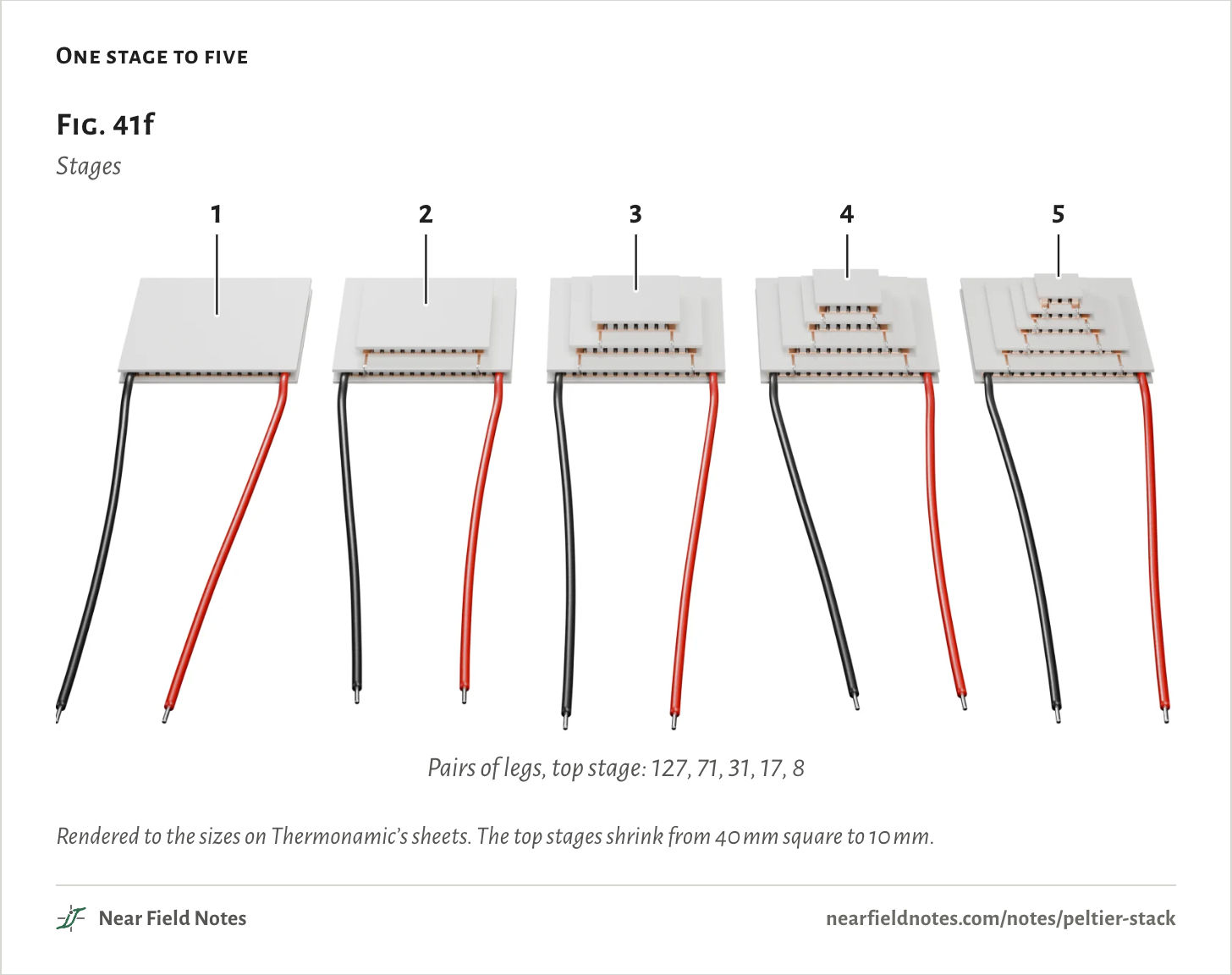
A factory multistage cooler makes the top stage weak with size instead. Each stage up has fewer pairs of legs, so it draws less, and one supply feeds them all in series.
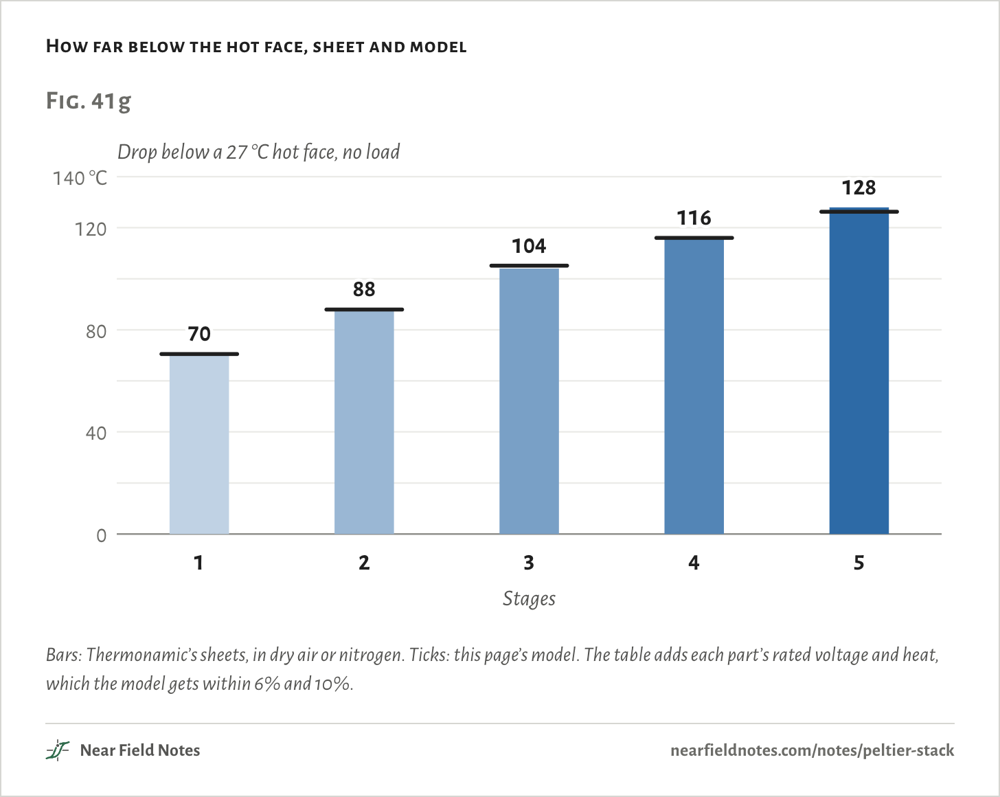
Thermonamic’s family is built on the 12706: 127 pairs at the bottom, then 71, 31, 17 and 8. With nothing on top, its sheets rate them 70, 88, 104, 116 and 128 °C below a 27 °C hot face.
One stage to five
Rendered to the sizes on Thermonamic’s sheets. The top stages shrink from 40 mm square to 10 mm.The numbers
Thermonamic’s TEC1-12706 and its TEC2 to TEC5 parts. Every bottom stage is the 12706’s 127 pairs.
Stages
Pairs of legs, bottom to top
Rated current
1
127
6.1 A
2
127 / 71
4.2 A
3
127 / 71 / 31
3.4 A
4
127 / 71 / 31 / 17
3.4 A
5
127 / 71 / 31 / 17 / 8
3.6 A
This page builds all five from the one-module model, each stage with the 12706’s legs and the sheet’s number of pairs. The only thing fitted per part is a leg size that matches its rated current, and that leaves the drop alone.
The model lands within two degrees of each sheet: 70.5 °C for one stage, up to 126.2 °C for five.
The gains shrink: 18 °C for the second stage, then 16, 12 and 12.
How far below the hot face, sheet and model
Bars: Thermonamic’s sheets, in dry air or nitrogen. Ticks: this page’s model. The table adds each part’s rated voltage and heat, which the model gets within 6% and 10%.The numbers
At a 27 °C hot face. The model is the one-module model with each part’s pairs of legs, and one leg size per part fitted so its best current lands on the sheet’s Imax; that fit leaves the drop alone.
Stages
Drop, sheet
Drop, model
Vmax, sheet
Vmax, model
Qmax, sheet
Qmax, model
1
70 °C
70.5 °C
16 V
16.1 V
61.4 W
59.0 W
2
88 °C
87.9 °C
15.4 V
16.2 V
28.2 W
28.4 W
3
104 °C
105.1 °C
15.8 V
16.0 V
13.2 W
13.3 W
4
116 °C
116.0 °C
14.5 V
15.1 V
9.1 W
8.2 W
5
128 °C
126.2 °C
14.4 V
14.5 V
5.22 W
4.9 W
Each stage carries every stage above it
−82.4 °C with half a watt on top
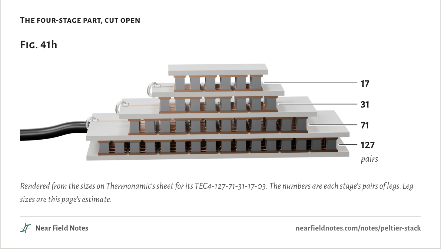
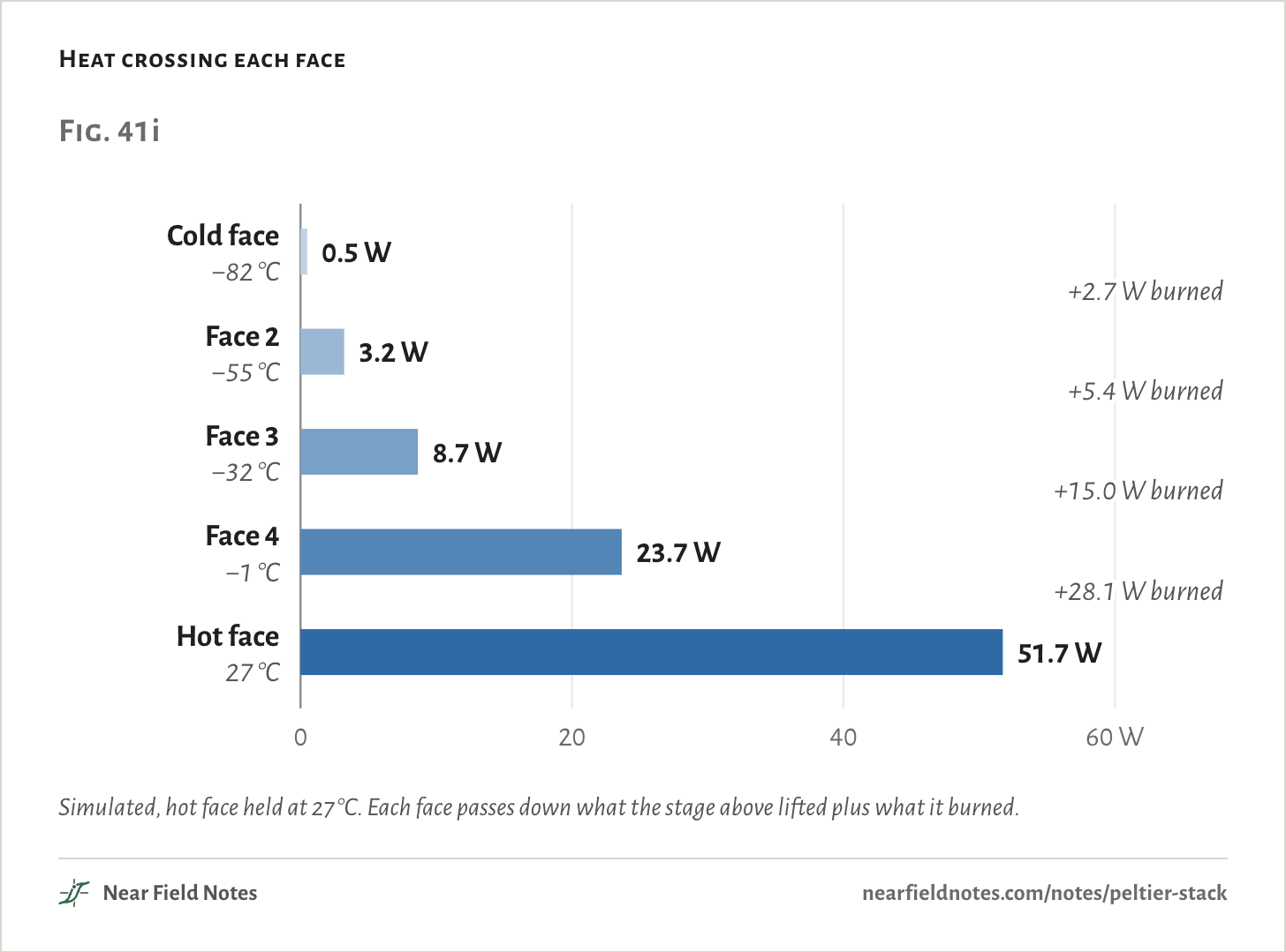
Here is the four-stage part with 0.5 W on its cold face, at its rated 3.4 A. It holds the cold face at −82.4 °C.
The top stage lifts the half watt and burns 2.7 W doing it, so the stage below must lift 3.2 W. Then 8.7 W, then 23.7 W.
The four-stage part, cut open
Rendered from the sizes on Thermonamic’s sheet for its TEC4-127-71-31-17-03. The numbers are each stage’s pairs of legs. Leg sizes are this page’s estimate.
Half a watt goes in at the top, and 51.7 W comes out the bottom.
That is why the stages shrink going up. Each one only has to be big enough for what lands on it, and the bottom one carries everything.
Heat crossing each face
Simulated, hot face held at 27 °C. Each face passes down what the stage above lifted plus what it burned.The numbers
Thermonamic’s four-stage part at 3.4 A, its rated current, hot face held at 27 °C. From the model, not a bench.
Stage, top down
Its faces
Lifts
Burns
Passes down
1, 17 pairs
−82.4 °C to −55.2 °C
0.50 W
2.71 W
3.21 W
2, 31 pairs
−55.2 °C to −31.6 °C
3.21 W
5.44 W
8.65 W
3, 71 pairs
−31.6 °C to −1.0 °C
8.65 W
15.01 W
23.66 W
4, 127 pairs
−1.0 °C to 27.0 °C
23.66 W
28.08 W
51.74 W
Load decides the stage count
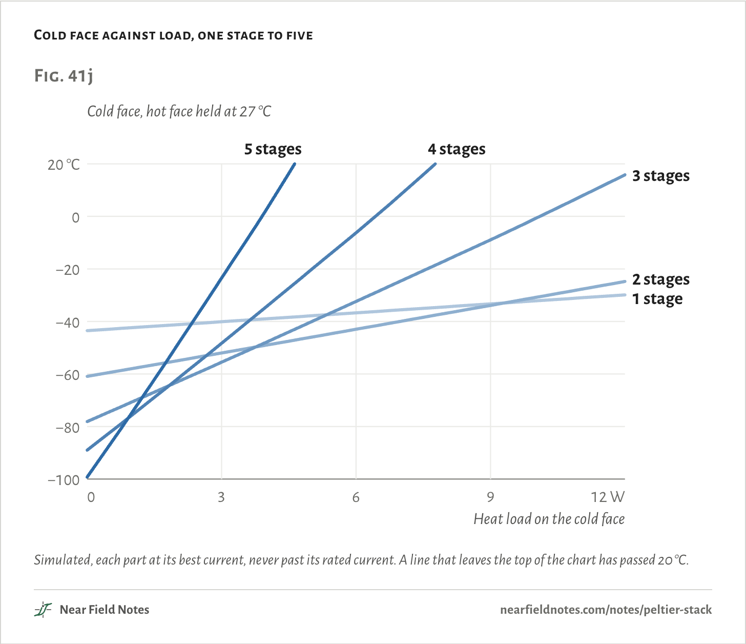
One stage wins past about 9 W
That growth is why the load decides how many stages to use. Each extra stage multiplies what the bottom one must carry, so a deep stack warms fast once it has a real load on it.
At 1 W the five-stage part gets no colder than the four: −74.7 °C against −75.7 °C.
At 10 W one plain module beats them all, at −32.2 °C. Two stages manage −30.9 °C, and three only −0.8 °C.
Cold face against load, one stage to five
Simulated, each part at its best current, never past its rated current. A line that leaves the top of the chart has passed 20 °C.
Load the cold face yourself
0 to 12 W
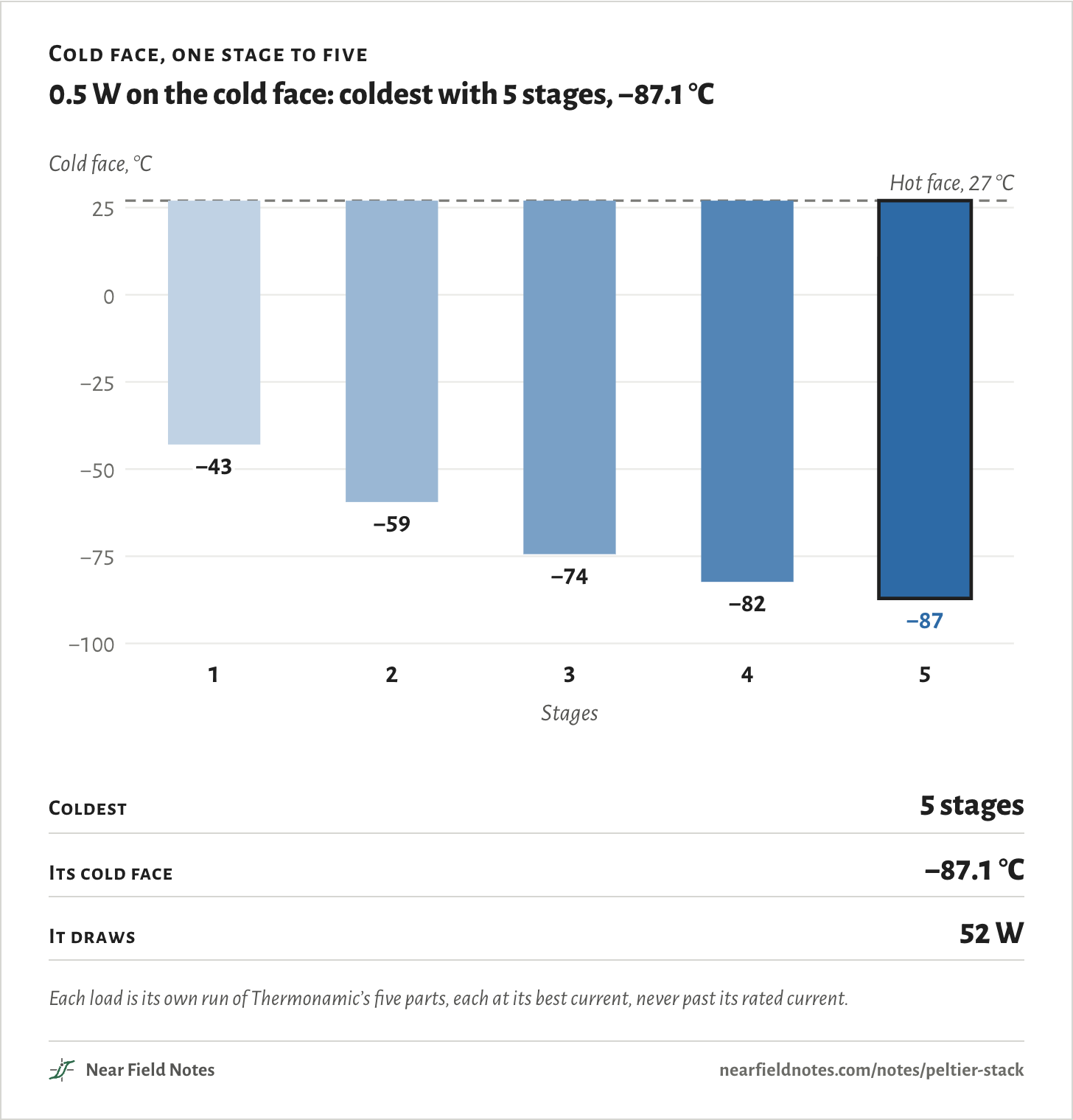
Set the heat on the cold face. Each bar runs down from the 27 °C hot face to where that part’s cold face settles, and the coldest is darkest.
Cold face, one stage to five
0.5 W on the cold face: coldest with 5 stages, −87.1 °C
Coldest
5 stages
Its cold face
−87.1 °C
It draws
52 W
Each load is its own run of Thermonamic’s five parts, each at its best current, never past its rated current.The numbers
Coldest face at each part’s best current, never above its sheet’s Imax; hot face held at 27 °C.
Load
1 stage
2
3
4
5
0 W
−43.5 °C
−60.9 °C
−78.1 °C
−89.0 °C
−99.3 °C
0.25 W
−43.2 °C
−60.2 °C
−76.3 °C
−85.7 °C
−93.2 °C
0.5 W
−42.9 °C
−59.4 °C
−74.4 °C
−82.4 °C
−87.1 °C
1 W
−42.4 °C
−58.0 °C
−70.7 °C
−75.7 °C
−74.7 °C
1.5 W
−41.8 °C
−56.5 °C
−66.9 °C
−68.9 °C
−62.1 °C
2 W
−41.2 °C
−55.0 °C
−63.1 °C
−62.1 °C
−49.3 °C
3 W
−40.1 °C
−52.0 °C
−55.5 °C
−48.3 °C
−23.5 °C
4 W
−39.0 °C
−49.0 °C
−47.9 °C
−34.4 °C
2.6 °C
5 W
−37.9 °C
−46.0 °C
−40.2 °C
−20.3 °C
Warmer than 27 °C
7 W
−35.6 °C
−39.9 °C
−24.6 °C
8.4 °C
Warmer than 27 °C
10 W
−32.2 °C
−30.9 °C
−0.8 °C
Warmer than 27 °C
Warmer than 27 °C
12 W
−29.9 °C
−24.8 °C
15.9 °C
Warmer than 27 °C
Warmer than 27 °C
Stages save power too
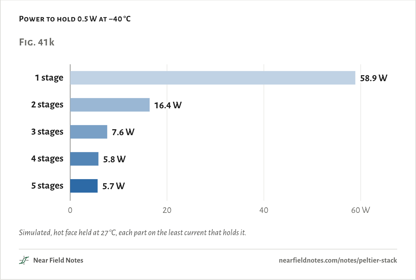
0.5 W at −40 °C
Where the load is small enough, stages also save power. A single stage holding 0.5 W at −40 °C is near its limit and runs hard.
It takes 58.9 W with one stage, 16.4 W with two, 7.6 W with three and 5.8 W with four. The fifth stage saves almost nothing more: 5.7 W.
Power to hold 0.5 W at −40 °C
Simulated, hot face held at 27 °C, each part on the least current that holds it.The numbers
Least power to hold 0.5 W there, every stage on one current, hot face held at 27 °C. From the model, not a bench.
Cold face
1 stage
2
3
4
5
−20 °C
15.6 W
5.9 W
3.1 W
2.5 W
2.7 W
−30 °C
28.6 W
10.0 W
4.9 W
3.9 W
3.9 W
−40 °C
58.9 W
16.4 W
7.6 W
5.8 W
5.7 W
−50 °C
Can’t
27.8 W
11.7 W
8.6 W
8.1 W
−60 °C
Can’t
Can’t
18.3 W
12.8 W
11.6 W
−70 °C
Can’t
Can’t
31.7 W
19.7 W
17.1 W
−80 °C
Can’t
Can’t
Can’t
35.7 W
27.2 W
What sets the floor
The legs, and the leaks
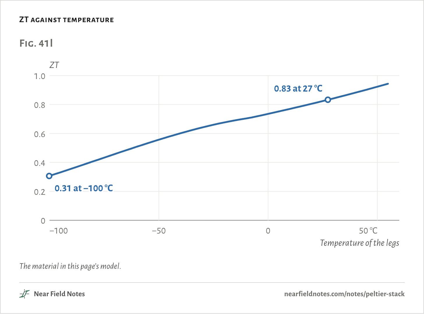
Two things set how cold a stack can get. The first is the legs. Bismuth telluride gets worse as it gets colder.
Its figure of merit, ZT, falls from 0.83 near room temperature to 0.31 at −100 °C, less than half. The coldest stages work with the weakest material. Note 40 shows what the same number does to a generator’s efficiency.
ZT against temperature
The material in this page’s model.The numbers
The model’s material: the TEC1-12706’s datasheet fit above −8 °C, Ferrotec’s published curves below, scaled to meet it.
Legs at
ZT
−100 °C
0.31
−90 °C
0.36
−80 °C
0.41
−70 °C
0.46
−60 °C
0.51
−50 °C
0.56
−40 °C
0.60
−30 °C
0.64
−20 °C
0.68
−10 °C
0.70
0 °C
0.73
10 °C
0.77
20 °C
0.80
30 °C
0.84
40 °C
0.88
50 °C
0.92
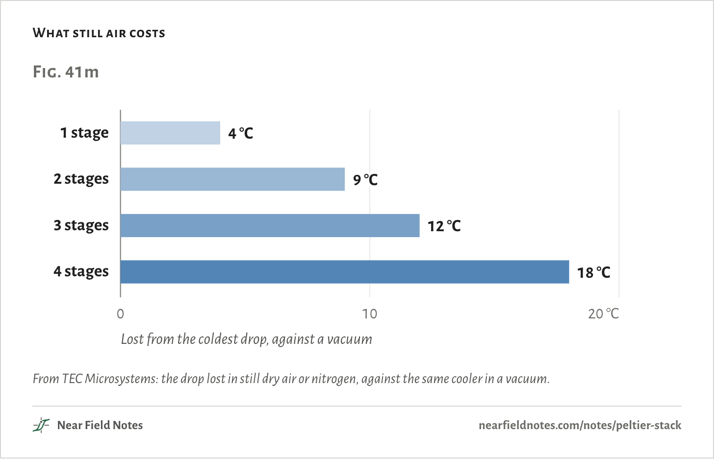
The second is leaks. The top stage is tiny and lifts little, so any heat that sneaks in costs it degrees.
By TEC Microsystems’ figures, still air or nitrogen costs a four-stage cooler about 18 °C against a vacuum, and xenon about 10. So deep stacks are sealed in a vacuum or a heavy gas.
The coldest catalog part found for this page is Marlow’s MI6030, six stages: 133 °C below its hot side, in a vacuum, with nothing on it.
What still air costs
From TEC Microsystems: the drop lost in still dry air or nitrogen, against the same cooler in a vacuum.
Who pays for four stages
9 times the price of one
At one shop on one day, a 40 mm single-stage module was $24.25 and a four-stage part $215.90. It pays wherever a sensor makes milliwatts of heat and works better cold.
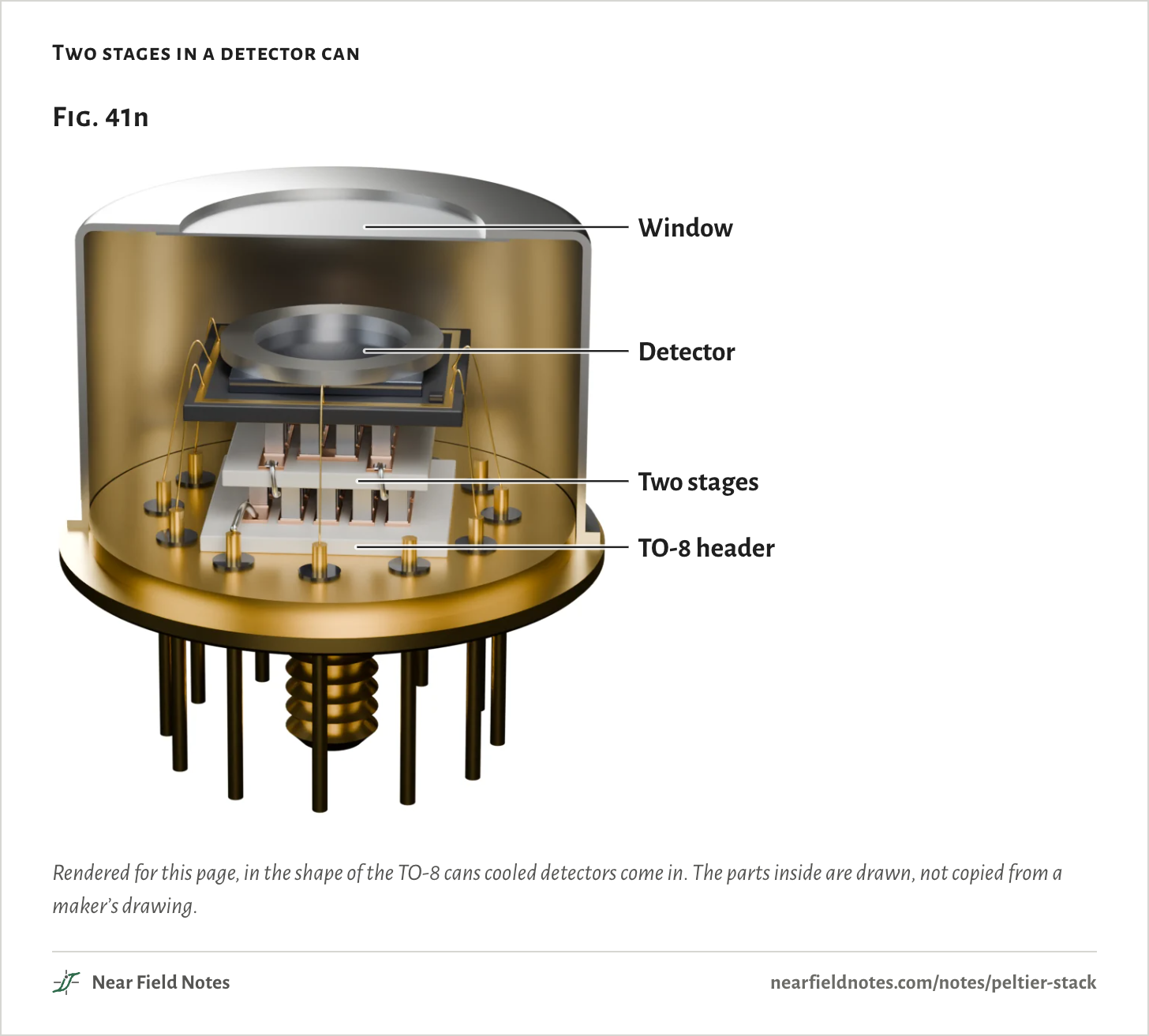
Two stages in a 4.1 g can cool the X-ray detectors in portable analyzers that read what a metal is made of. Amptek seals its cans with a vacuum inside and calls the cooling “critical to the development of portable XRF analyzers.”
Four stages hold infrared detectors at −78 °C. Thorlabs lists one at $4,932.27, $962.01 more than the same detector with no cooler.
And six stages hold the infrared detector in Hubble’s Wide Field Camera 3 at 145 K, −128 °C.
Two stages in a detector can
Rendered for this page, in the shape of the TO-8 cans cooled detectors come in. The parts inside are drawn, not copied from a maker’s drawing.
Where stacks work, and what they cost
Fig. 41o
Stages
Where
Cold end
Price
2, hand-stacked
Hobby cloud chambers: a 12710 module on 12 V under a 12709 on 5 V
Below about −25 °C
$23.25 to $34.20 a module
2
X-ray detectors in portable analyzers, sealed with a vacuum inside a 4.1 g can
Prices read on 12 November 2026, for one piece: Custom Thermoelectric for the modules, Thorlabs for the detector. The cloud-chamber line is one published build, the X-ray line Amptek’s, and the Hubble line STScI’s.
How many stages?
Four questions
The choice comes down to the load, and to whether the parts are already on the bench.
Key to a Peltier cooler
How many stages?
1aAbout 10 W or more on the cold faceOne stage, sized for the load
1bA few watts or lessGo to 2
2aBuying one partGo to 3
2bBuilding from two ordinary modulesGo to 4
3aA watt or moreTwo or three stages
3bUnder a wattFour stages, sealed from the air; five only for a few hundred milliwatts
4aTwo suppliesAbout 5 V on top, 12 V under it: 19.5 °C colder than one module
4bOne 12 V supplyBoth in series: 5.6 °C colder than one module, on half the power
The watts are what sits on the cold face, from Fig. 41j, with the hot face held at 27 °C. A real heatsink runs warmer and moves every line up. Steps 4a and 4b are the two modules of Fig. 41a on its fan heatsink, with nothing on the cold face.
Conditions
Simulated
Every temperature and wattage on this page comes from a model of the TEC1-12706 fitted to Thermonamic’s datasheet, and from stacks built out of it. None was measured on a bench.
Module
TEC1-12706, 40 × 40 × 3.8 mm, 127 pairs of legs. The standard model of a module, with its Seebeck coefficient, resistance and thermal conductance each changing with temperature, fitted to the sheet’s ratings at 27 and 50 °C and to its charts. With its hot face held at 27 °C it gets 70.5 °C below it, against the sheet’s 70.
Material
The sheet’s data stop near −8 °C, so below that the material follows the shape of Ferrotec’s published module curves, scaled to meet the fit.
Stacks
Each stage is a module in the same model. The heat leaving one stage’s hot face enters the next stage’s cold face at the same temperature, with nothing between them.
Heatsink
0.30 °C per watt to a 25 °C room, with its fan. Nothing on the cold face, and no air reaching it, unless a line says otherwise.
Family
Thermonamic’s TEC2 to TEC5 parts, each stage the 12706’s legs with the sheet’s count of pairs, and one leg size per part fitted so its best current lands on the sheet’s rated current. Hot face held at 27 °C, each part at its best current, never past its rated one.
Render
Blender. The modules, heatsink and family follow their sheets’ sizes. The detector can is drawn for this page.
Fitted to datasheets. Nothing on this page has been measured on a bench.
Limits
No air reaches the cold faces in the model. Let room air in, at 0.02 W per °C, and the fan-heatsink results warm by 1.5 to 3.3 °C: −27.7 °C, −27.2 °C and −45.3 °C.
Stages touch with nothing between them. The grease and ceramic between two hand-stacked modules would cost a little more.
Below about −8 °C the material rests on Ferrotec’s curves, not on the 12706’s sheet.
Sheets print each stage’s pairs of legs but not their size, so the model gives every stage the 12706’s legs. Thermonamic’s TEC2-127-127-06, two stages of 127 pairs, is rated 93 °C, where two identical stages reach 71 °C in the model, so its stages must differ. Kryotherm’s four-stage part with the same pairs, 127, 71, 31 and 17, comes out 9 °C better in the model than on its sheet.
Every part here runs at its best current. A real controller may hold a temperature at less.
The five-stage part lifts 1.07 W at a 100 °C drop in the model, on 52 W, where its sheet reads about 1.14 W on about 50 W.
Files
sim/tec.pyThe TEC1-12706 model and its fit to the datasheet
sim/cascade.pyThe stacks: two modules at set voltages and at their best currents, the family, the voltage sweeps, the loads and the check against published parts
render/stack.pyThe two rigs and the cut stack in Blender
render/cascade.pyThe family and the four-stage part cut open