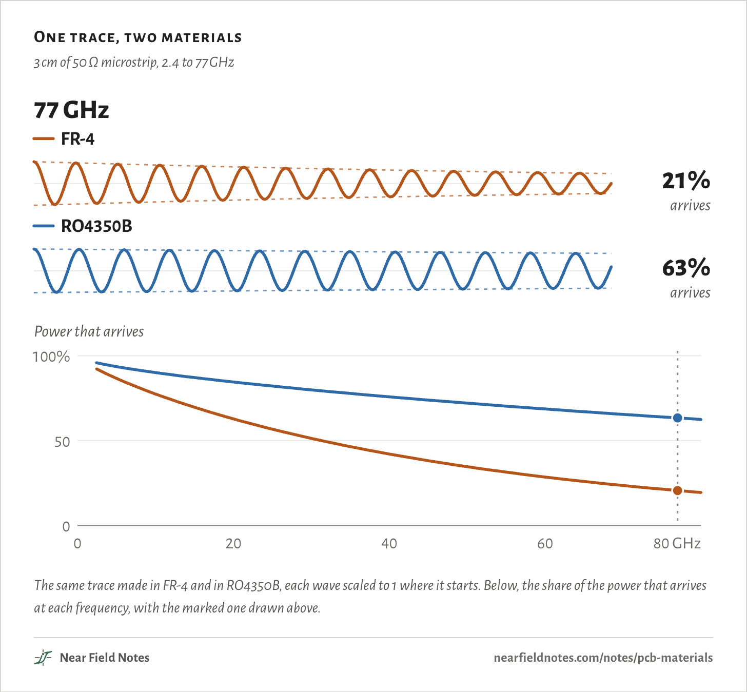
Not at 2.4 GHz. A 3 cm trace on common FR-4 delivers 92% of its power there, against 96% on Rogers RO4350B. At 77 GHz the same trace delivers 21% on FR-4, so radar boards put one thin layer of Rogers on top.
The wave is the signal along the trace at the frequency marked below. As the frequency climbs, more of it turns to heat in the FR-4 on the way.
RO4350B loses about a fifth as much in each cycle, so at 77 GHz 63% of its power arrives.
One trace, two materials
3 cm of 50 Ω microstrip, 2.4 to 77 GHz
The same trace made in FR-4 and in RO4350B, each wave scaled to 1 where it starts. Below, the share of the power that arrives at each frequency, with the marked one drawn above.The numbers
Over the 3 cm trace. Each material at its own 50 Ω width, with the same copper.
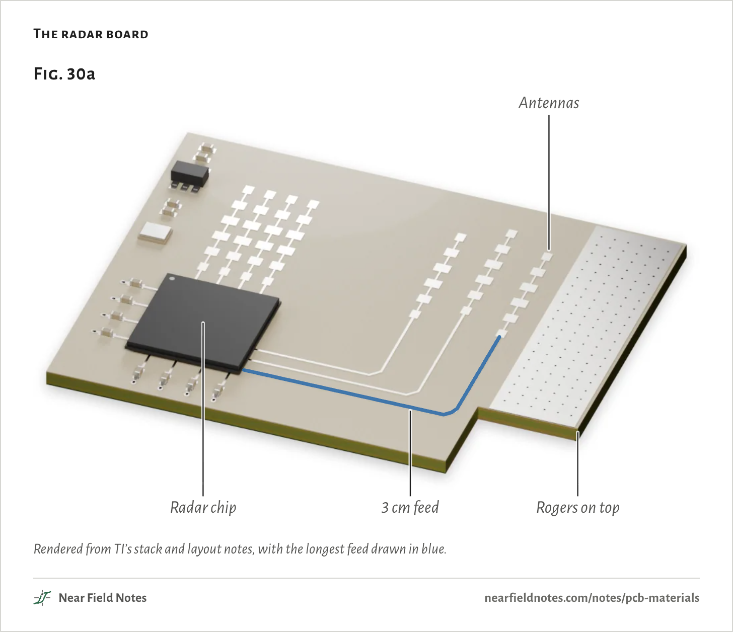
50 Ω microstrip on layer 1, 0.193 mm wide; the longest is 30 mm
Antennas
Four receive and three transmit columns of patches
The Rogers is 7% of the board’s 1.43 mm. On that layer, a 3 cm feed delivers 56% of its power at 77 GHz.
That is less than the opening’s 63%. TI’s Rogers is 0.10 mm thick, half the 0.21 mm under the opening’s trace. A 50 Ω trace on it is 0.19 mm wide against 0.43 mm, and the narrower copper loses more: 0.51 dB/cm against 0.29.
Made in FR-4 prepreg of the same thickness, the same feed would deliver 21%. In RO3003, TI’s other choice for the top layer, 73%.
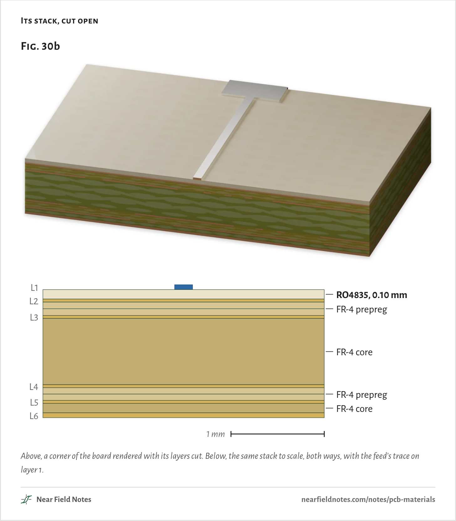
Its stack, cut open
Above, a corner of the board rendered with its layers cut. Below, the same stack to scale, both ways, with the feed’s trace on layer 1.The numbers
From TI’s SPRACG5, Figure 1, as processed. 1080 is the prepreg’s glass style.
Layer
Thickness
Metric
Copper L1
2.067 mil
52.5 µm
RO4835 core
4.000 mil
101.6 µm
Copper L2
1.260 mil
32.0 µm
IT-180A 1080
2.830 mil
71.9 µm
IT-180A 1080
2.830 mil
71.9 µm
Copper L3
1.260 mil
32.0 µm
IT-180A core
28.000 mil
711.2 µm
Copper L4
1.260 mil
32.0 µm
IT-180A 1080
2.691 mil
68.4 µm
IT-180A 1080
2.691 mil
68.4 µm
Copper L5
1.260 mil
32.0 µm
IT-180A core
4.000 mil
101.6 µm
Copper L6
2.067 mil
52.5 µm
Total
56.22 mil
1428 µm
What a board is made of
Glass, resin and copper
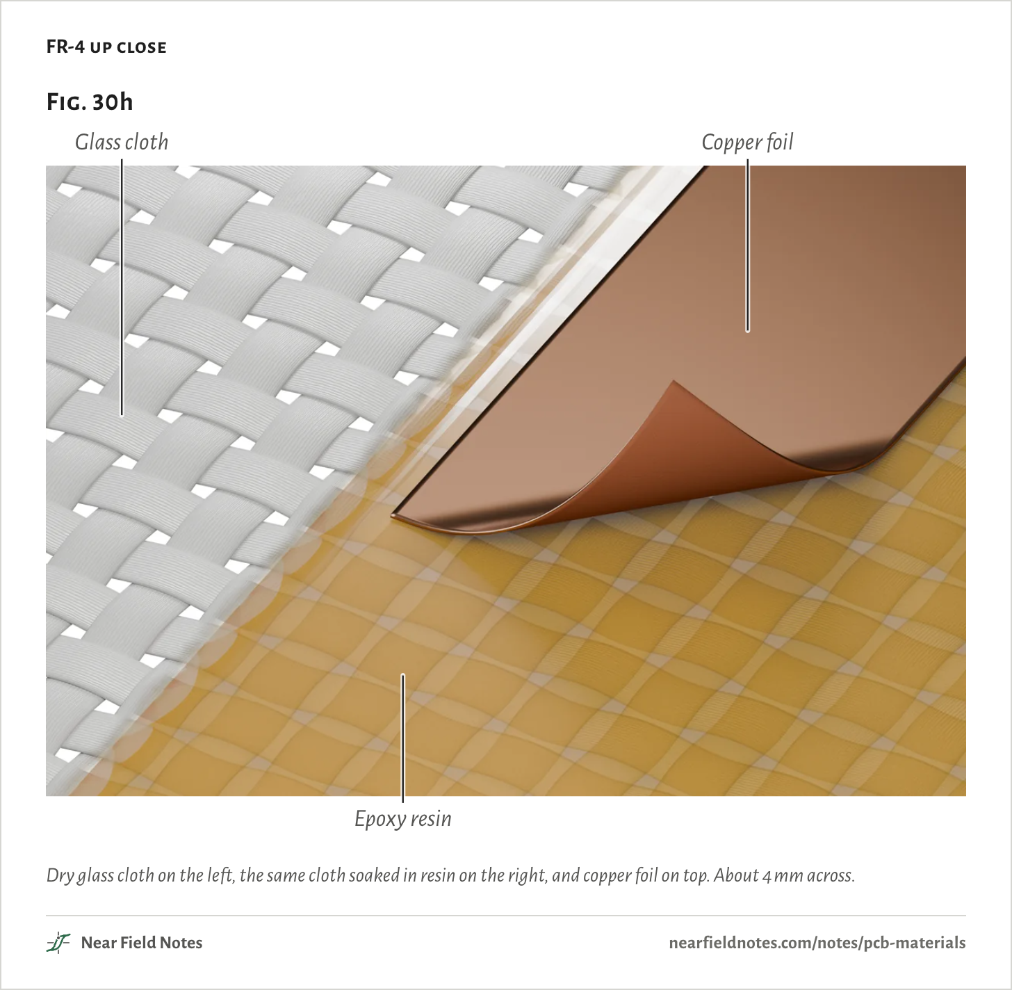
TI’s two materials are made the same way. A rigid board is glass cloth soaked in resin, with copper foil outside.
A core comes cured, with copper on both faces. Prepreg is the same cloth with its resin not yet cured. Pressed hot, it melts, glues the stack together and sets.
Change the resin and the glass, and four numbers change.
Dk. How fast a signal travels, and how wide a 50 Ω trace is.
Df. The share of each cycle that turns to heat.
Z-expansion. How much the board swells when it is soldered.
Thermal conductivity, k. How well it carries heat away.
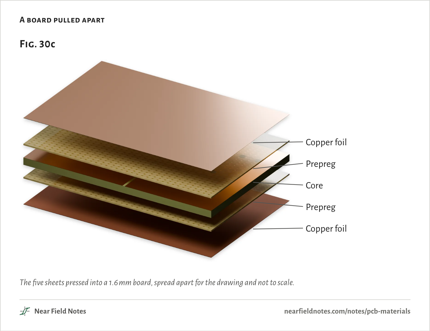
A board pulled apart
The five sheets pressed into a 1.6 mm board, spread apart for the drawing and not to scale.The numbers
JLCPCB’s JLC04161H-7628 stack, 1.6 mm. Exploded for the drawing, not to scale.
Sheet
Thickness
What it is
Copper foil
35 µm
The outer layers, etched after pressing
Prepreg
0.2104 mm
Glass cloth in resin not yet cured, which glues the stack
Core
1.0954 mm
Glass cloth in cured resin, copper on both sides: the inner layers
Prepreg
0.2104 mm
Copper foil
35 µm
Loss grows with frequency
Df, and the field’s share
Of those four numbers, Df sets the loss. The dielectric’s loss is its Df times the share of the field’s energy that runs through it, and it grows in step with frequency:
That is the opening’s FR-4 trace at 77 GHz. Its copper adds 0.32 dB/cm, for 2.29 dB/cm in all, so the dielectric takes 86% of the loss.
Copper’s part grows only with the square root of frequency. Over the 3 cm, decibels turn back into the share that arrives:
PP0=10−αL/10
=10−2.29 dB/cm × 3 cm/10=21%
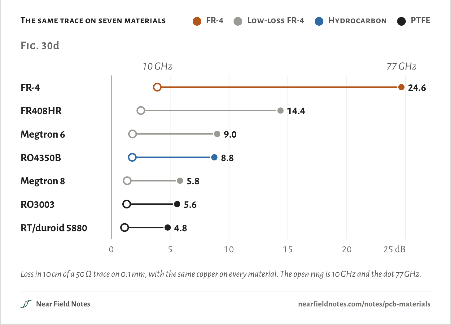
Fig. 30d uses a third trace: 50 Ω on a 0.1 mm sheet, the thickness of the radar board’s top layer. It is made in seven materials, from the four families met one at a time further down.
At 10 GHz, 10 cm of it loses 3.9 dB on FR-4 and 1.3 dB on RO3003. At 77 GHzFR-4 loses 24.6 dB, and 0.3% arrives. Megtron 6 and RO4350B land side by side, 9.0 dB and 8.8 dB.
The same trace on seven materials
FR-4
Low-loss FR-4
Hydrocarbon
PTFE
Loss in 10 cm of a 50 Ω trace on 0.1 mm, with the same copper on every material. The open ring is 10 GHz and the dot 77 GHz.The numbers
50 Ω microstrip on 0.1 mm, 1 oz rolled copper on every material, 10 cm long.
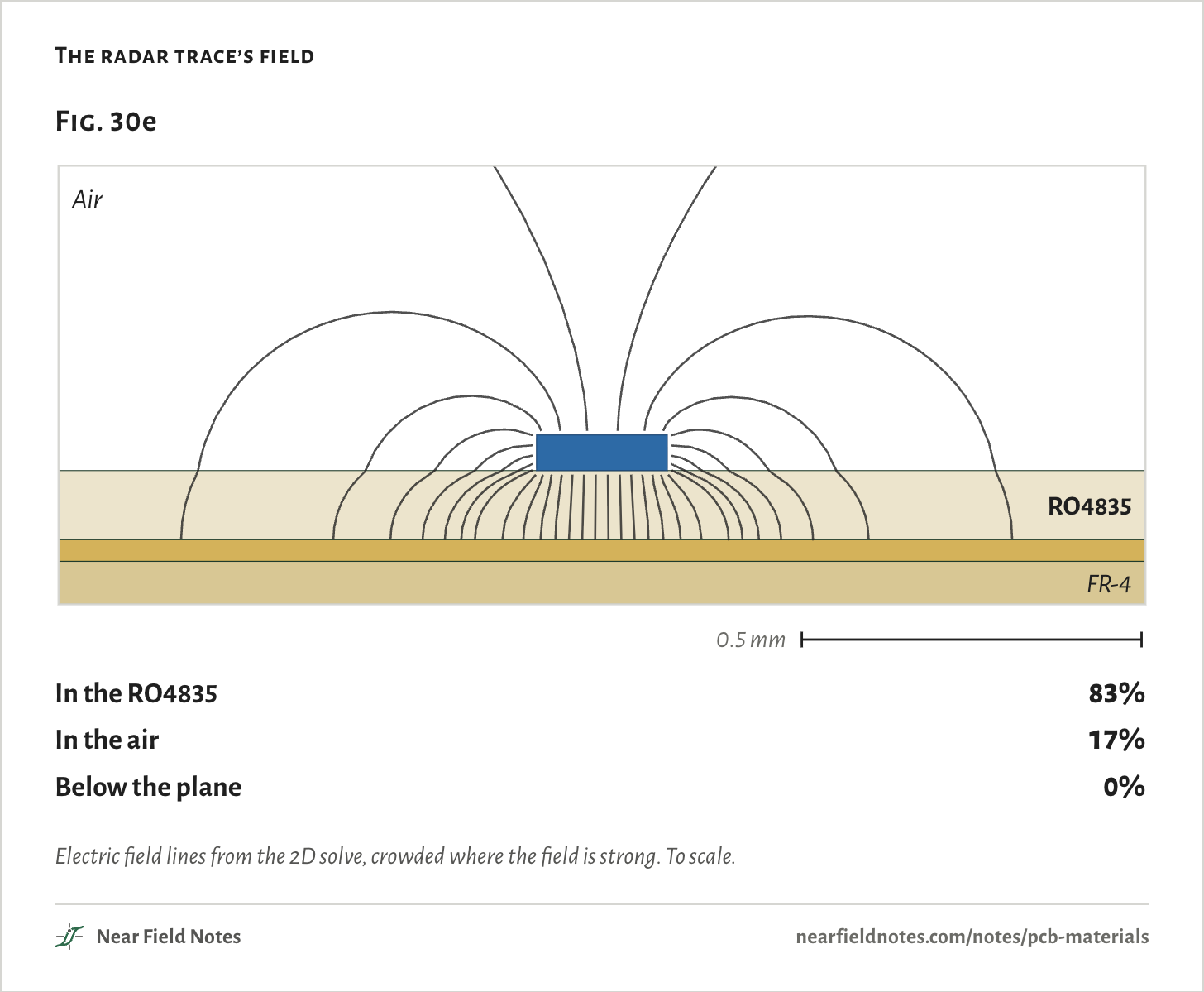
A trace’s field runs from the trace to the copper plane under it. On TI’s board that plane is layer 2, 0.10 mm down, so the field crosses the Rogers and the air above and goes no further.
83% of its energy is in the RO4835 and 17% in the air. The layer 2 copper is 32 µm thick, many skin depths at 77 GHz, so none reaches the FR-4. The FR-4 under it only holds the board together.
The radar trace’s field
Electric field lines from the 2D solve, crowded where the field is strong. To scale.The numbers
From the 2D solve of TI’s layer 1 trace, 0.193 mm wide on 0.1016 mm of RO4835, 50.1 Ω.
Where
Share of the field’s energy
In the RO4835
83.0%
In the air
17.0%
Below the layer 2 plane
0%
Heat moves the phase
Dk against temperature
Dk matters to a radar too. It drifts as a board warms, and the wave slows or speeds up with it. A long feed at a high frequency is many wavelengths long, so a small drift moves its phase a lot:
Δφ=360°×N×12s×TCDk×ΔT
=360°×22.6×12×0.86×200 ppm/°C×125 °C=87°
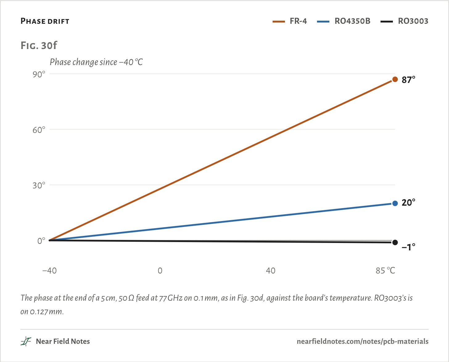
That is a 5 cm length of Fig. 30d’s 0.1 mm trace on FR-4 at 77 GHz, warmed from −40 to 85 °C.
Phase drift
FR-4
RO4350B
RO3003
The phase at the end of a 5 cm, 50 Ω feed at 77 GHz on 0.1 mm, as in Fig. 30d, against the board’s temperature. RO3003’s is on 0.127 mm.The numbers
50 Ω microstrip at 77 GHz: FR-4 and RO4350B on 0.1 mm, RO3003 on 0.127 mm.
Material
TCDk
Wavelengths in 5 cm
Share of a Dk change felt
Phase change
FR-4
+200 ppm/°C
22.6
0.857
87.0°
RO4350B
+50 ppm/°C
21.0
0.846
20.0°
RO3003
−3 ppm/°C
19.6
0.839
−1.1°
572
Phase drift
87° on FR-4, −1° on RO3003
Field marks. A 5 cm feed on Fig. 30d’s FR-4 is 22.6 wavelengths long at 77 GHz. From −40 to 85 °C its Dk climbs 2.5%, and its end’s phase moves 87°. On RO4350B it moves 20°, on RO3003 −1°.
Look-alike. Low loss read as low drift. RT/duroid 5880 has about RO3003’s Df, 0.0009 against 0.0010, but its Dk drifts −125 ppm/°C against −3.
Range. Rogers gives FR-4 a typical +200 ppm/°C and RO4350B +50. Higher-Dk RO3000 laminates drift far more: RO3010 is −395.
Habitat. Radars and phased arrays, whose feeds must stay in step. TI credits RO3003 with rolled copper for lower loss and better phase repeatability, and RO4835 for better yield.
573
Heat leaving a part
k, through the board
Thermal conductivity, k, matters once a part runs hot. Heat from a part on top has to cross the board to reach a heatsink underneath. Each square centimeter of a layer holds it back by its thickness over its conductivity:
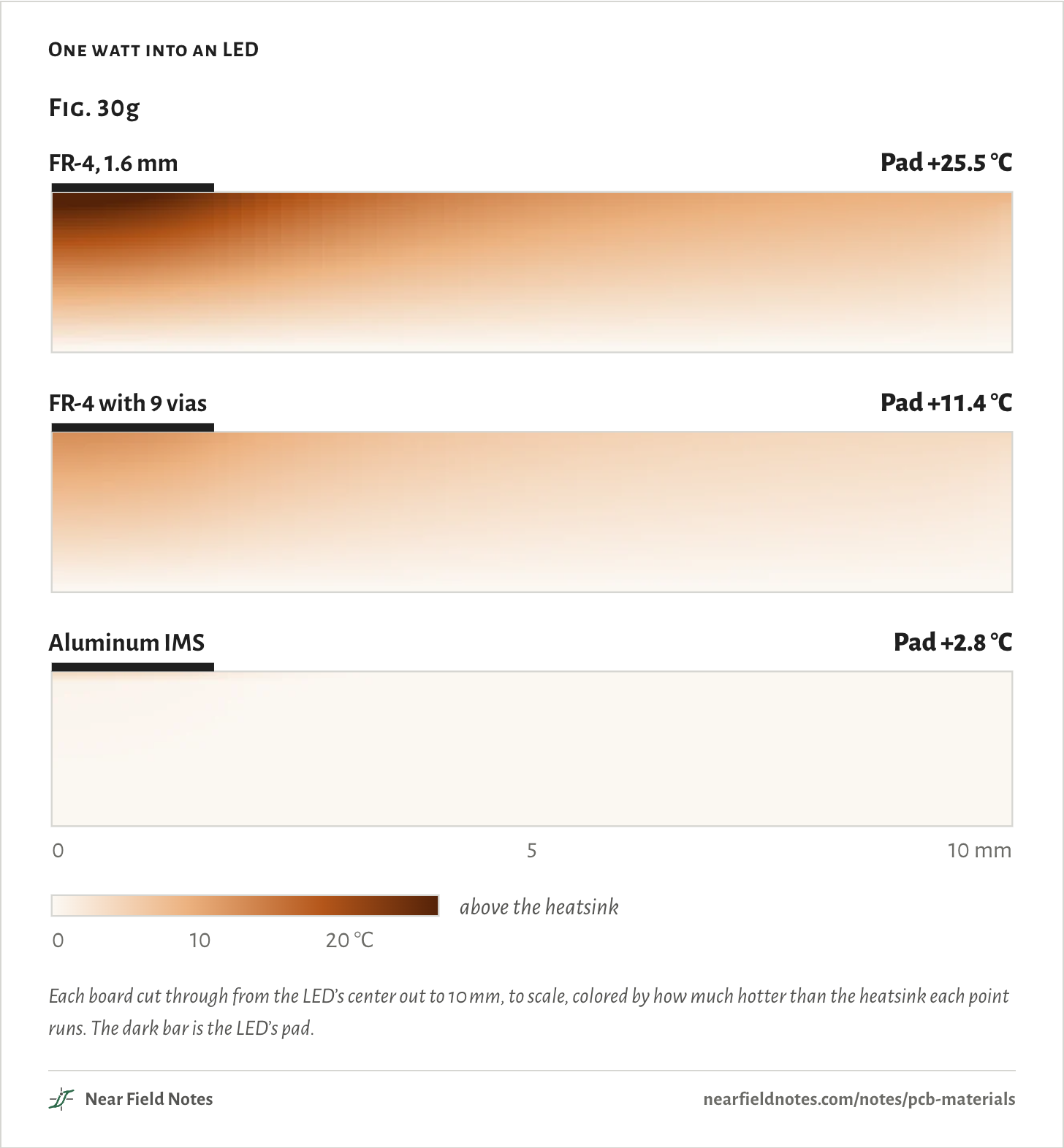
The first is plain 1.6 mmFR-4. The second is the thin dielectric of an aluminum IMS board, which sits on 1.5 mm of aluminum.
One watt into an LED
Each board cut through from the LED’s center out to 10 mm, to scale, colored by how much hotter than the heatsink each point runs. The dark bar is the LED’s pad.The numbers
1 W into a 3 × 3 mm pad, a 1 oz pour 10 mm in radius, the board’s bottom on a heatsink held at 25 °C, no air cooling.
Board
Build
Pad above the heatsink
FR-4, 1.6 mm
1.6 mm FR-4, k 0.4 W/m·K, 35 µm copper both sides
25.5 °C
FR-4 with 9 vias
The same, with nine 0.3 mm plated vias under the pad
11.4 °C
Aluminum IMS
76 µm dielectric, k 2.2 W/m·K, on 1.5 mm aluminum, k 138 W/m·K
2.8 °C
574
Heat rise
25.5 °C hotter on FR-4, 2.8 °C on aluminum
Field marks. One watt into a 3 × 3 mm LED pad, the board on a heatsink. Through 1.6 mm of FR-4 the pad runs 25.5 °C hotter than the heatsink, with nine vias under it 11.4 °C, and on aluminum IMS 2.8 °C.
Look-alike. High Tg. Isola’s 370HR, Tg 180 °C, conducts the same 0.4 W/m·K as other FR-4.
Range.FR-4 conducts about 0.4 W/m·K and Bergquist’s HT-04503 IMS dielectric 2.2. Aluminum is 138, aluminum nitride 170 and copper 386.
Habitat. LED bulbs. Teardowns of GE’s and Cree’s A19 bulbs and the LIFX BR30 found aluminum boards. Note 7 follows the same heat the other way, into a pad being soldered.
575
Standard FR-4
Glass-epoxy, on almost every board
With the four numbers in hand, here are the families one at a time, starting with the board most people order. Note 25 follows the opening’s FR-4 trace at 5.5 GHz.
FR-4 up close
Dry glass cloth on the left, the same cloth soaked in resin on the right, and copper foil on top. About 4 mm across.The numbers
Part
What it is
Glass cloth
2116 style, as woven: yarns about 0.42 mm apart
Resin
Epoxy, flame-retardant
Copper foil
Electrodeposited, its rough side toward the resin to grip it
576
Standard FR-4
Df 0.018, $4 for five boards
Field marks. Nan Ya’s NP-155F, a JLCPCB 4-layer material, has a Df of 0.016 to 0.019 from 1 to 10 GHz. Shengyi’s S1141 swells 4.5% in thickness from 50 to 260 °C and delaminates after 2 minutes at 288 °C.
Look-alike.FR-4 read as one material. The name is a flame-retardant grade: Panasonic lists Megtron 4, Df 0.007 at 13 GHz, as FR-4.0 too.
Range. The opening’s 3 cm trace delivers 92% at 2.4 GHz, 77% at 10 GHz and 21% at 77 GHz.
Habitat. Almost every board, from JLCPCB’s default 2-layer Tg 135 FR-4 to OSH Park’s. Note 3’s 2.4 GHz antenna is etched on 1 mm of it.
577
High-Tg and low-loss FR-4
New resins, the same process
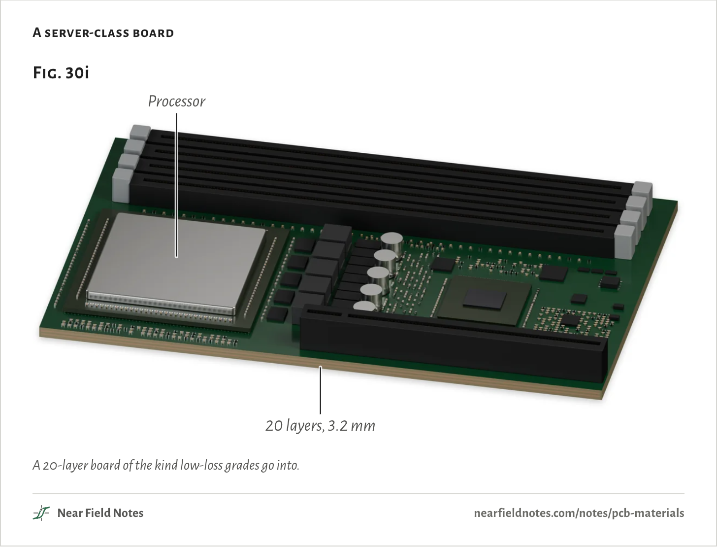
Change only the resin and a board can take more soldering heat, or lose less. Fabs press these grades the way they press FR-4.
A server-class board
A 20-layer board of the kind low-loss grades go into.The numbers
A render of the kind of board low-loss grades go into, not a particular product.
Part
What it is
Board
165 × 105 mm, 3.2 mm thick
Layers
20 copper layers, signal and ground in turn
578
High-Tg and low-loss FR-4
Df 0.025 down to 0.0012
Field marks. Isola’s high-Tg 370HR lasts 30 minutes at 288 °C and swells 2.8% from 50 to 260 °C. Low-loss Megtron 6 cuts Df to 0.004 at 10 GHz, Megtron 8 to 0.0012 at 14 GHz.
Look-alike. High Tg read as low loss. 370HR’s Tg is 180 °C, but its Df, 0.025 at 10 GHz, tops NP-155F’s, and its long-term rating is 130 °C.
Range. AMD’s cost table puts Megtron 6 at 3.5 times FR-4. Cisco measured 37% more loss on it at 10 GHz with standard foil than with smooth HVLP.
Habitat. Servers and routers. Panasonic called Megtron 6 “the standard of the high-end server router equipment material” in 2015.
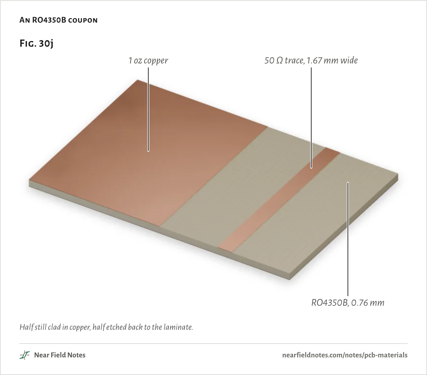
The laminate most people mean by “Rogers” is ceramic-filled hydrocarbon, the first step up from FR-4 for RF.
An RO4350B coupon
Half still clad in copper, half etched back to the laminate.The numbers
Part
What it is
Laminate
Rogers RO4350B, 0.030 in, design Dk 3.66
Copper
1 oz electrodeposited
Trace
50 Ω microstrip, 1.67 mm wide
580
Hydrocarbon-ceramic
Df 0.0037, processed like FR-4
Field marks. RO4350B is ceramic-filled hydrocarbon on woven glass, with a Df of 0.0037 at 10 GHz and a design Dk of 3.66. Rogers says it runs through standard FR-4 processes with no sodium etch.
Look-alike. PTFE. “Rogers” often stands for any RF laminate, but Rogers calls RO4000 “reinforced hydrocarbon/ceramic laminates – not PTFE”.
Range. At JLCPCB five boards cost 46.5 times as much as in FR-4, but at retail the laminate costs about 4 times: €147.15 per square foot for 60 milRO4003C against €35.60 for 1.57 mmFR-4. Its filler wears out drills in 2,000 to 3,000 hits.
Habitat. The top layer of TI’s radar board, as RO4835, the same laminate made to resist oxidation.
581
PTFE
The lowest loss, and soft
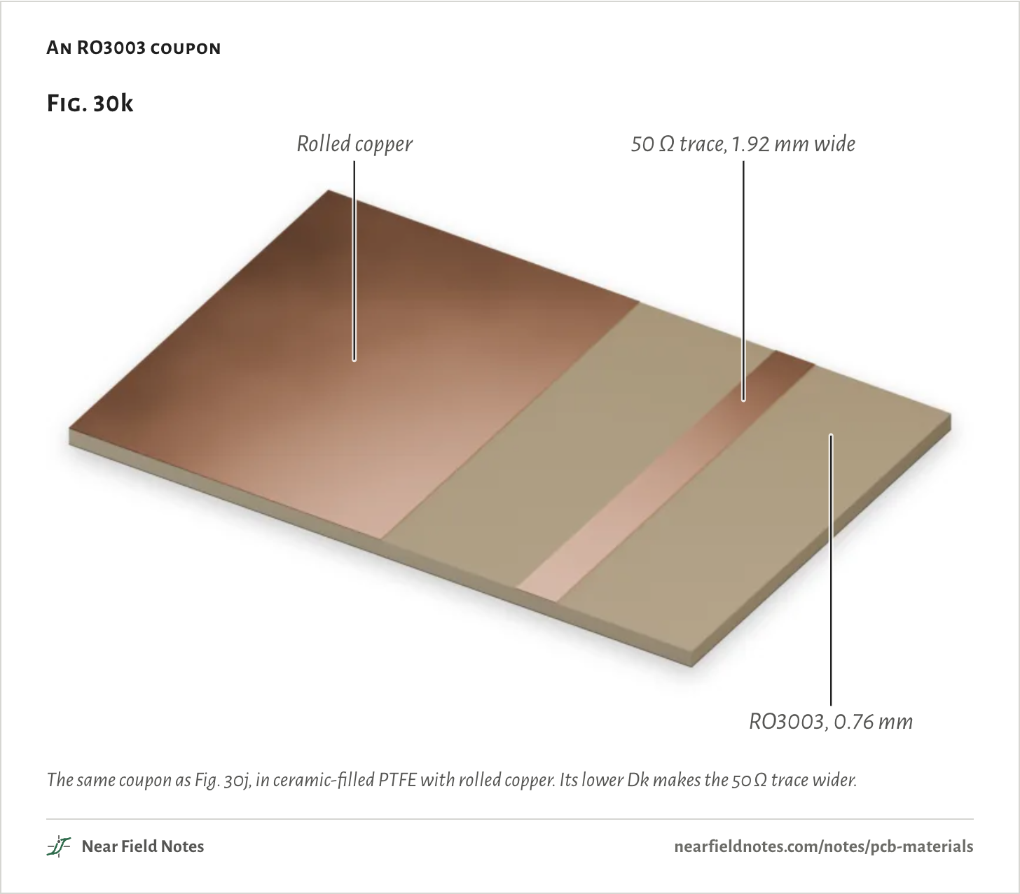
For the lowest loss and the steadiest Dk, boards go to PTFE, the plastic in Teflon, filled with ceramic or glass.
An RO3003 coupon
The same coupon as Fig. 30j, in ceramic-filled PTFE with rolled copper. Its lower Dk makes the 50 Ω trace wider.The numbers
Part
What it is
Laminate
Rogers RO3003, ceramic-filled PTFE, 0.030 in, Dk 3.00
Copper
1 oz rolled
Trace
50 Ω microstrip, 1.92 mm wide
582
PTFE
Df 0.0010, Dk steady with heat
Field marks. RO3003 has a Df of 0.0010 at 10 GHz, and its Dk drifts only −3 ppm/°C. On the opening’s trace at 77 GHz, 3 cm of it delivers 78%.
Look-alike. RT/duroid 5880. It is PTFE too, with glass microfiber, but it swells 237 ppm per degree in thickness against RO3003’s 25.
Range. Rogers’ fab guide calls these laminates soft and asks for support through scrubbing. RO4003C is about 18 times as stiff as 5880. Before plating, the hole walls need plasma or a sodium etch.
Habitat.77 GHz car radar. Rogers sells RO3003 for it, and teardowns of Bosch’s mid-range radar and Autoliv’s 77 GHz radar found hybrid PTFE and FR-4 boards.
583
Polyimide flex
No glass, so it bends
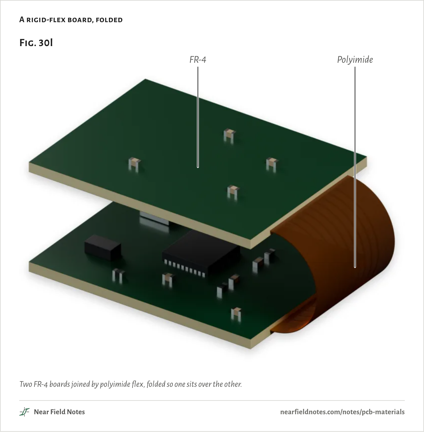
Leave out the glass and a board can bend. Flex circuits are thin polyimide film with copper on it.
A rigid-flex board, folded
Two FR-4 boards joined by polyimide flex, folded so one sits over the other.The numbers
Part
What it is
Rigid
FR-4 1.0 mm, green mask
Flex
polyimide 50 um core, 18 um copper, 37 um coverlay
Fold
12 mm wide, 16 mm free between the boards
584
Polyimide flex
Bends, and takes up water
Field marks. DuPont’s Pyralux AP is polyimide with no adhesive layer. Its Df is 0.003 at 10 GHz, and DuPont rates it for 6,000 flex cycles. It takes up 0.8% water.
Look-alike. LCP. Liquid crystal polymer bends too, with lower loss: Rogers gave its ULTRALAM 3850HT a Df of 0.0020 at 10 GHz. Murata builds its mmWave 5G antenna modules on its own LCP board.
Range. Five 2-layer flex boards, 0.11 mm thick, cost $16.00 at JLCPCB. Würth’s rigid-flex rules give a bend radius of 10 times the flex’s thickness for two copper layers.
Habitat. Cables inside phones and cameras, and rigid-flex boards that fold into tight cases: FR-4 where the parts sit, polyimide where it bends.
585
Aluminum IMS
Insulated metal substrate
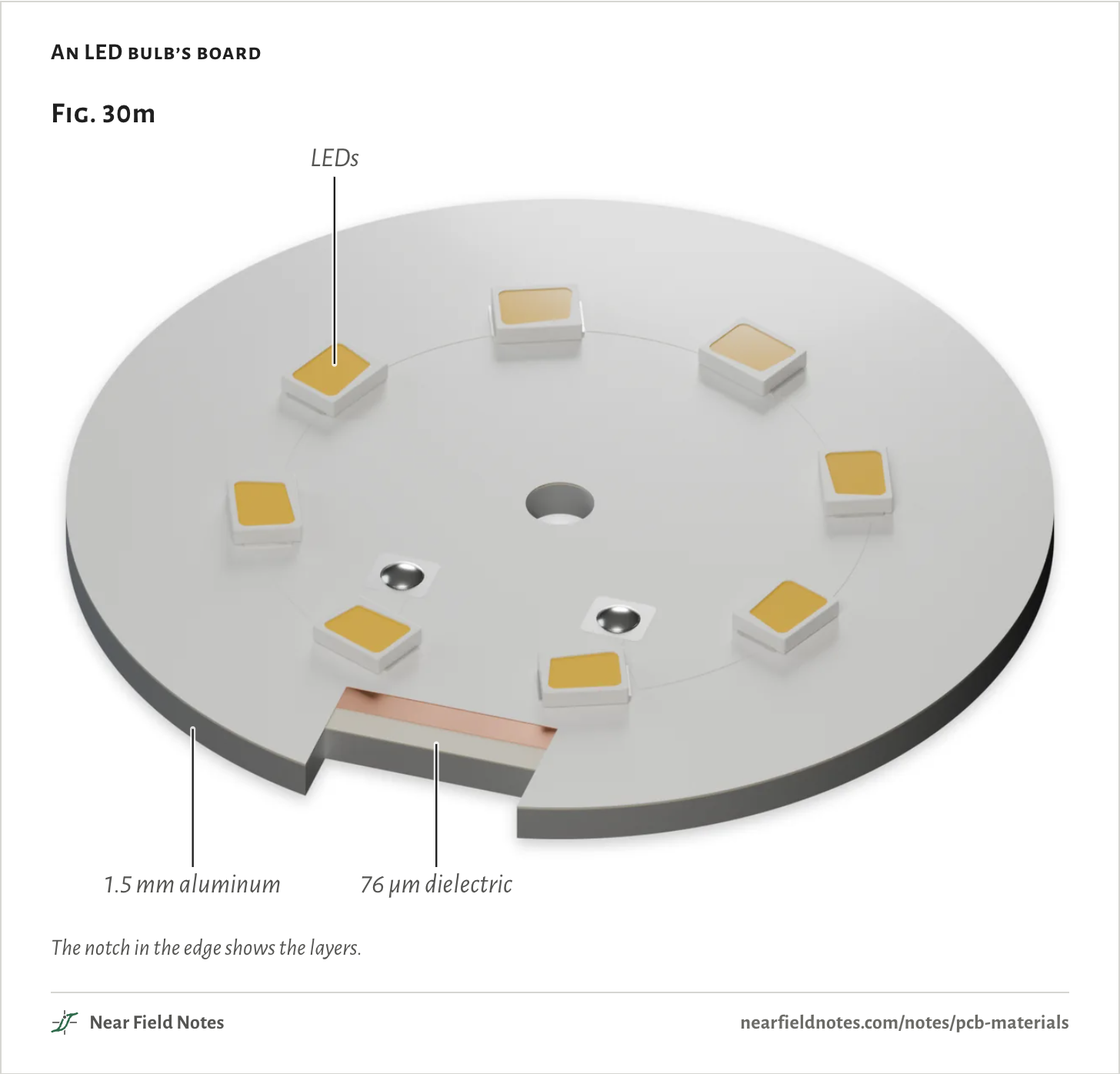
When the job is heat, the base can be metal. An IMS board is one copper layer on a thin dielectric on aluminum.
An LED bulb’s board
The notch in the edge shows the layers.The numbers
Part
What it is
Board
40 mm across
Base
1.5 mm aluminum
Dielectric
76 µm, as Bergquist HT-04503
Copper
35 µm
LEDs
Eight 2835 (2.8 x 3.5 x 0.75 mm)
586
Aluminum IMS
k 2.2, against FR-4’s 0.4
Field marks. A filled polymer dielectric between the copper and an aluminum base. Bergquist’s HT-04503 is 76 µm thick at 2.2 W/m·K, on aluminum at 138. In Fig. 30g it holds a 1 W LED to 2.8 °C above the heatsink.
Look-alike. A board that conducts like metal. The aluminum under it conducts 63 times better than the dielectric, so the dielectric’s thickness and k are what to read a datasheet for.
Range. JLCPCB offers aluminum only as a 1-layer board, with what it calls a “1W” dielectric. Five cost $4.00, the same promotional price as FR-4.
Habitat. LED bulbs and lamps, and power parts that sit on a heatsink.
587
Ceramic
Copper bonded to ceramic
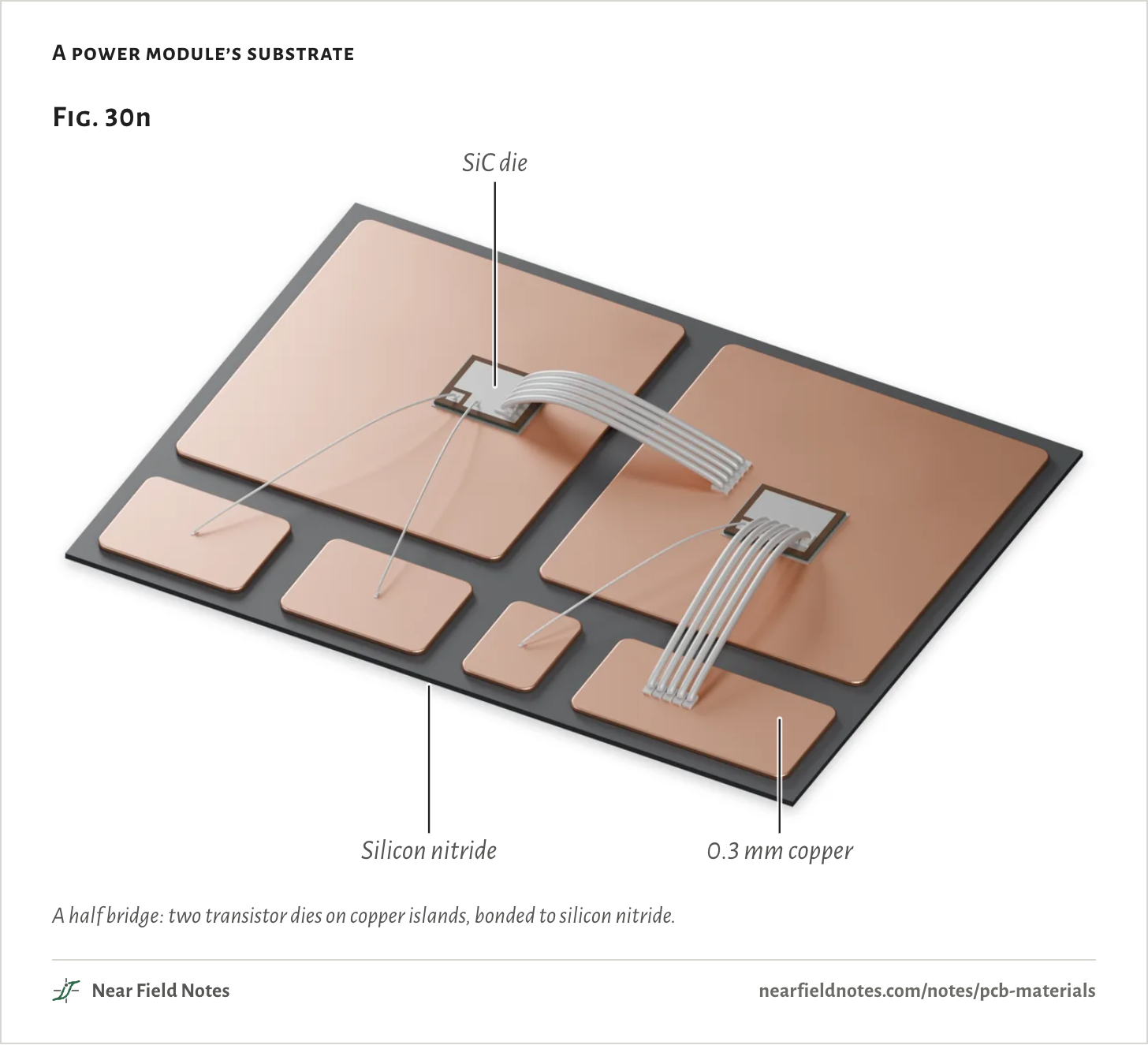
For hundreds of watts, power modules bond thick copper straight onto a ceramic sheet.
A power module’s substrate
A half bridge: two transistor dies on copper islands, bonded to silicon nitride.The numbers
Part
What it is
Ceramic
Si3N4 AMB 40 x 30 x 0.32 mm
Copper
0.3 mm
Dies
SiC MOSFET 4.6 x 4.0 x 0.18 mm, sintered
Wires
Al 380 um source, 125 um gate
588
Ceramic
Up to 170 W/m·K, and brittle
Field marks. Copper 0.127 to 0.8 mm thick, bonded to a ceramic sheet. Rogers’ curamik line rates silicon nitride at 90 W/m·K and aluminum nitride at 170, against 24 for alumina.
Look-alike. IMS. Both carry hot parts, but an IMS board insulates with 76 µm of polymer at 2.2 W/m·K, and a ceramic substrate with a sheet at 24 to 170.
Range. Ceramics are brittle: CoorsTek gives its aluminas a fracture toughness of 4 to 5 MPa·m½.
Habitat. Power modules in EV traction inverters. onsemi lists a silicon nitride isolator in its EliteSiC traction module, and Rogers sells its silicon nitride substrates for traction inverters.
589
What five boards cost
One fab, one day
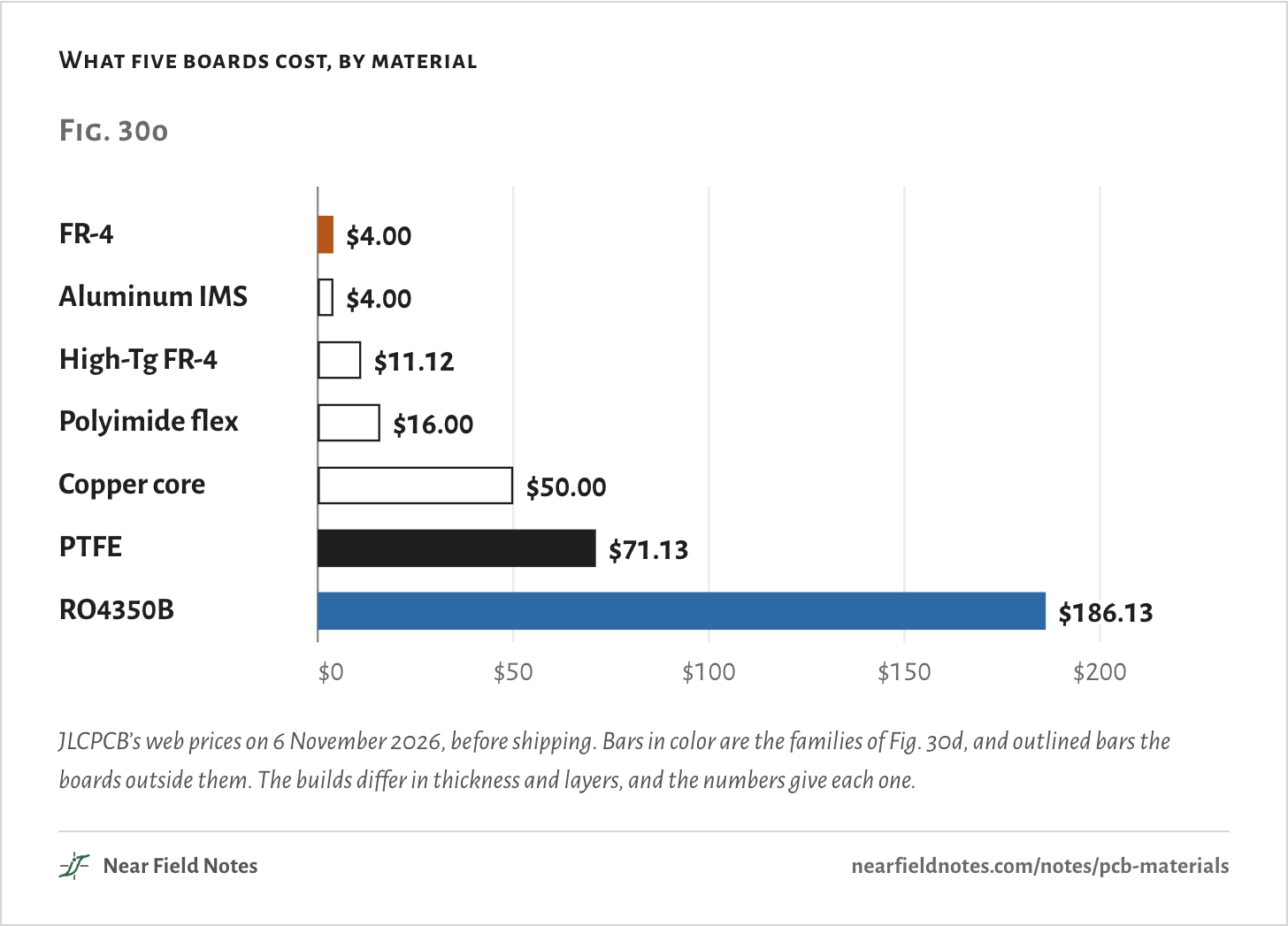
Price is why boards mix materials. Fig. 30o lines up one fab’s price for five 100 × 100 mm boards in each material, from $4.00 in FR-4 to $186.13 in RO4350B.
FR-4’s and aluminum’s $4.00 are promotions, so the ratios say more about the price list than the laminates. Copper core is the IMS build with a copper base in place of aluminum.
What five boards cost, by material
JLCPCB’s web prices on 6 November 2026, before shipping. Bars in color are the families of Fig. 30d, and outlined bars the boards outside them. The builds differ in thickness and layers, and the numbers give each one.The numbers
JLCPCB’s web prices, 6 November 2026, before shipping. The FR-4 and aluminum prices are promotional. The PTFE and RO4350B quotes include the ENIG finish they require.
Material
Build
Five boards
Against FR-4
FR-4
1.6 mm, 2 layers
$4.00
1.0×
Aluminum IMS
1.6 mm, 1 layer
$4.00
1.0×
High-Tg FR-4
KB6165F, 1.6 mm, 2 layers
$11.12
2.8×
Polyimide flex
0.11 mm, 2 layers
$16.00
4.0×
Copper core
1.6 mm, 1 layer
$50.00
12.5×
PTFE
ZYF300CA-C, 0.76 mm, 2 layers
$71.13
17.8×
RO4350B
1.52 mm, 2 layers
$186.13
46.5×
Mixing materials in one board
Hybrid stackups
A hybrid puts the costly laminate only where the field runs. On TI’s radar board that is one sheet on top, because a microstrip’s field ends at the plane under it, as Fig. 30e shows.
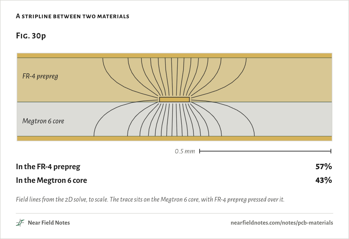
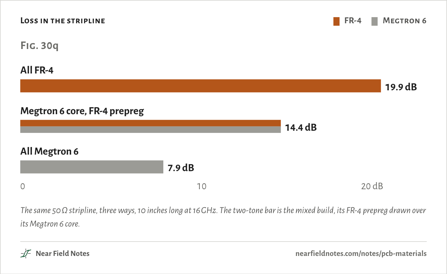
A stripline is different. It runs between two planes, so its field fills the layers above and below it. With Megtron 6 on one side and FR-4 on the other, the loss lands about halfway: 14.4 dB over 10 inches at 16 GHz, against 19.9 dB all FR-4 and 7.9 dB all Megtron 6.
A stripline between two materials
Field lines from the 2D solve, to scale. The trace sits on the Megtron 6 core, with FR-4 prepreg pressed over it.The numbers
50 Ω stripline, 0.113 mm wide, 18 µm copper.
Where
Share of the field’s energy
FR-4 prepreg above, and beside the trace
56.9%
Megtron 6 core below
43.1%
Loss in the stripline
FR-4
Megtron 6
The same 50 Ω stripline, three ways, 10 inches long at 16 GHz. The two-tone bar is the mixed build, its FR-4 prepreg drawn over its Megtron 6 core.The numbers
10 in of 50 Ω stripline: 0.13 mm core below, 0.15 mm prepreg above, 18 µm copper with smooth HVLP foil.
Build
16 GHz
Arrives
28 GHz
Arrives
All FR-4
19.9 dB
1%
32.9 dB
0%
Megtron 6 core, FR-4 prepreg
14.4 dB
4%
23.4 dB
0%
All Megtron 6
7.9 dB
16%
12.2 dB
6%
Hybrids come with rules, and the fab sets most of them.
Keep the stack balanced.IPC-6012 allows 0.75% bow and twist on a board with surface-mount parts, and its automotive addendum leaves unbalanced builds to agreement between buyer and maker. TI’s board has a 4 mil core at each face: RO4835 at the top, FR-4 at the bottom.
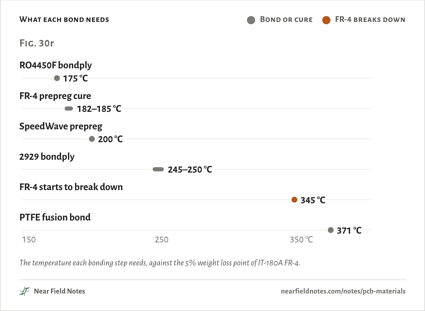
Bond at FR-4’s temperatures. Fusion-bonding PTFE takes 371 °C or more, past the 345 °C where IT-180AFR-4 starts to break down. So PTFE hybrids are glued with prepreg or bondply that cures at 175 to 250 °C.
Mind the swelling. From 50 to 260 °C, IT-180A swells 2.7% in thickness and RO4350B about 0.67%. The plated holes through both have to take the difference.
Ask the fab first. Each material drills and cleans its holes its own way. Rush PCB notes that each mix needs its own UL approval, and that a hybrid only pays when about three quarters of the thickness is the cheaper material.
What each bond needs
Bond or cure
FR-4 breaks down
The temperature each bonding step needs, against the 5% weight loss point of IT-180AFR-4.The numbers
From Rogers’ processing guides for RO4450F, SpeedWave 300P, 2929 and PTFE fusion, Isola’s 370HR guide for the FR-4 cure, and ITEQ’s IT-180A sheet for 5% weight loss.
Step
Temperature
RO4450F bondply
175 °C
FR-4 prepreg cure
182–185 °C
SpeedWave prepreg
200 °C
2929 bondply
245–250 °C
FR-4 starts to break down
345 °C
PTFE fusion bond
371 °C
Choosing a material
Heat, bending and loss
Start from what the board has to do. Most boards end at FR-4, and the rest add a costly material only where it pays.
Key to board materials
Which material does my board need?
1aA part on it must shed watts through the boardGo to 6
1bNo part runs that hotGo to 2
2aThe board has to bend or foldPolyimide flex
2bIt stays flatGo to 3
3aOn FR-4 a trace loses more than the link can spareGo to 4
3bIt can spare the lossFR-4
4aFast digital links run on many layersLow-loss FR-4 grade
4bRF runs on one or two layersGo to 5
5aIt needs the lowest loss and a phase that holds with heatPTFE on those layers
5bLow loss is enoughHydrocarbon on those layers
6aA few watts from LEDs or a regulatorAluminum IMS
6bHundreds of watts from power switchesCeramic
TI’s radar board in Fig. 30a ends at 5b: RO4835 on layer 1 and FR-4 under it. Bosch’s and Autoliv’s radars, built with PTFE and FR-4, end at 5a.
Pick a material yourself
Seven materials, 1 to 77 GHz
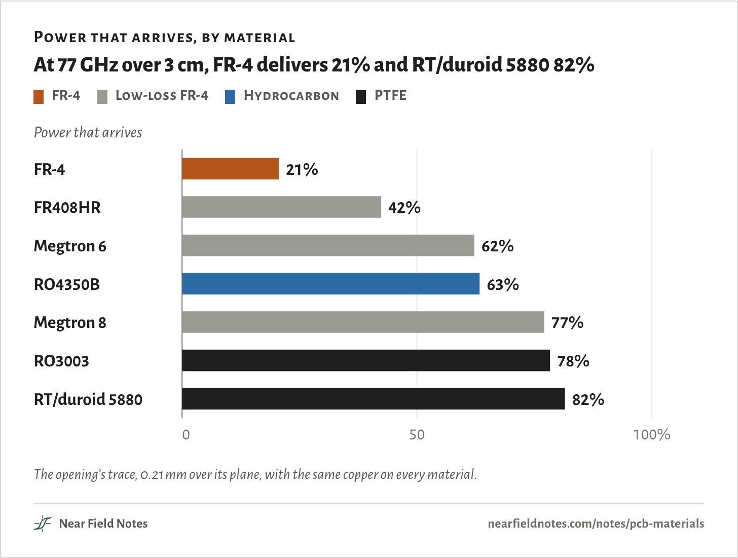
Choose a frequency and a length for the opening’s trace. Each bar is the share of the power that arrives, with the trace made in that material at its own 50 Ω width.
At 2.4 GHz over 3 cm, every material delivers 92% or more. At 77 GHz they spread from 21% to 82%.
Length of the trace
Power that arrives, by material
At 77 GHz over 3 cm, FR-4 delivers 21% and RT/duroid 5880 82%
FR-4
Low-loss FR-4
Hydrocarbon
PTFE
The opening’s trace, 0.21 mm over its plane, with the same copper on every material.The numbers
Each material at its own 50 Ω width over 0.21 mm, with the same copper.
Over 3 cm
FR-4
FR408HR
Megtron 6
RO4350B
Megtron 8
RO3003
RT/duroid 5880
1 GHz
96%
97%
98%
98%
98%
98%
98%
2.4 GHz
92%
95%
96%
96%
97%
97%
97%
5 GHz
87%
91%
93%
94%
95%
95%
96%
10 GHz
77%
85%
90%
90%
93%
93%
94%
16 GHz
68%
80%
86%
87%
91%
91%
92%
28 GHz
53%
70%
80%
81%
87%
88%
89%
40 GHz
42%
62%
75%
76%
84%
85%
87%
60 GHz
29%
50%
68%
69%
80%
81%
84%
77 GHz
21%
42%
62%
63%
77%
78%
82%
Conditions
Opening trace
50 Ω microstrip on JLCPCB’s JLC04161H-7628 stack: 0.2104 mm of prepreg over the layer 2 plane, 1 oz standard electrodeposited copper, Sq 3.2 µm, no solder mask. In FR-4, Dk 4.4 and Df 0.018, it is 0.37 mm wide. In RO4350B, at its design Dk of 3.66 and Df 0.0037, 0.43 mm. The explorer puts all seven materials on this trace. 2.4 GHz is taken at 2.45 GHz.
Fig. 30d
50 Ω microstrip on 0.1 mm, 1 oz rolled copper, Sq 0.4 µm, the same on every material.
Radar trace
TI’s layer 1: 4 mil RO4835 LoPro at its process Dk of 3.48 and Df 0.0037, 2.067 mil copper with LoPro foil, Sq 0.9 µm, 0.19 mm wide. The FR-4 swap is 4 mil of IT-180A 1080 prepreg at Dk 3.7 and Df 0.018, with standard foil. The RO3003 swap is 5 mil, with rolled copper.
Materials
Dk and Df at 10 GHz from each datasheet: FR408HR 3.65 and 0.0095, Megtron 6 3.61 and 0.004, RO4350B 3.66 and 0.0037, RO3003 3.00 and 0.0010, RT/duroid 5880 2.20 and 0.0009. Megtron 8, 3.08 and 0.0012, is Panasonic’s 14 GHz figure. FR-4 is a typical 4.4 and 0.018, inside NP-155F’s Df range.
Loss
A 2D field solve of each cross-section. The dielectric loses its share of the field’s energy times its Df, as in the formula above. Copper loss comes from incremental inductance, with the Hammerstad roughness model. Df is held at its datasheet value at every frequency. Against Rogers’ measured 1.3 dB per inch for 5 mil RO3003G2 at 77 GHz, the solve gives 1.28.
Stripline
50 Ω between two planes: 0.13 mm core below, 0.15 mm prepreg above, 18 µm copper with HVLP foil.
Phase
Each material’s TCDk from its datasheet, with FR-4 at Rogers’ typical +200 ppm/°C. The 2D solve gives how much of a Dk change the wave feels. FR-4 and RO4350B on 0.1 mm, RO3003 on 0.127 mm.
Heat
Steady heat conduction in a disc 15 mm in radius: 1 W into a pad with the area of 3 × 3 mm, a 1 oz copper pour 10 mm in radius, and the bottom held at 25 °C. FR-4 at 0.4 W/m·K. The vias count as 2.2% copper under the pad. The IMS is 76 µm at 2.2 W/m·K on 1.5 mm of aluminum at 138.
Video
The video’s 92% at 2.4 GHz and 21% at 77 GHz came from two traces, a 2.4 GHz board’s on JLCPCB’s 4-layer stack and TI’s layer 1 made in FR-4. The opening sweeps the first alone, which gives the same two numbers.
Renders
Blender, from the stacks and builds named in each figure’s numbers.
Simulated only. Nothing on this page has been measured on a board yet.
Limits
Real Df creeps up with frequency, so the 77 GHz losses favor FR-4 if anything.
No solder mask, bends or vias. In a hybrid, vias run through both materials, and Note 17 covers what their stubs cost.
Radiation and surface waves aren’t counted.
The phase drift is a straight-line estimate from each TCDk. Rogers’ measured curves bend.
The heat runs have a perfect heatsink and no air, so only the boards differ.
Prices are one fab on one day, and FR-4’s and aluminum’s are promotional.
Files
sim/xsec.pyThe 2D field solve: impedance, field shares and loss of a trace in any layered stack
sim/loss.pyFig. 30d’s seven materials, TI’s radar trace and its swaps, the phase drift and the striplines
sim/site.pyThe opening’s trace from 2.4 to 80 GHz, the explorer’s seven materials, and the field lines
sim/thermal.pyThe 1 W LED on three boards
sim/materials.pyEach material’s Dk and Df and each copper foil’s roughness, with sources
render/stack.pyThe radar board, its stack and the 4-layer board pulled apart
render/parts.pyThe weave, the coupons, the server board, the rigid-flex, the LED board and the power module