What does a Peltier module make when it’s run as a generator?
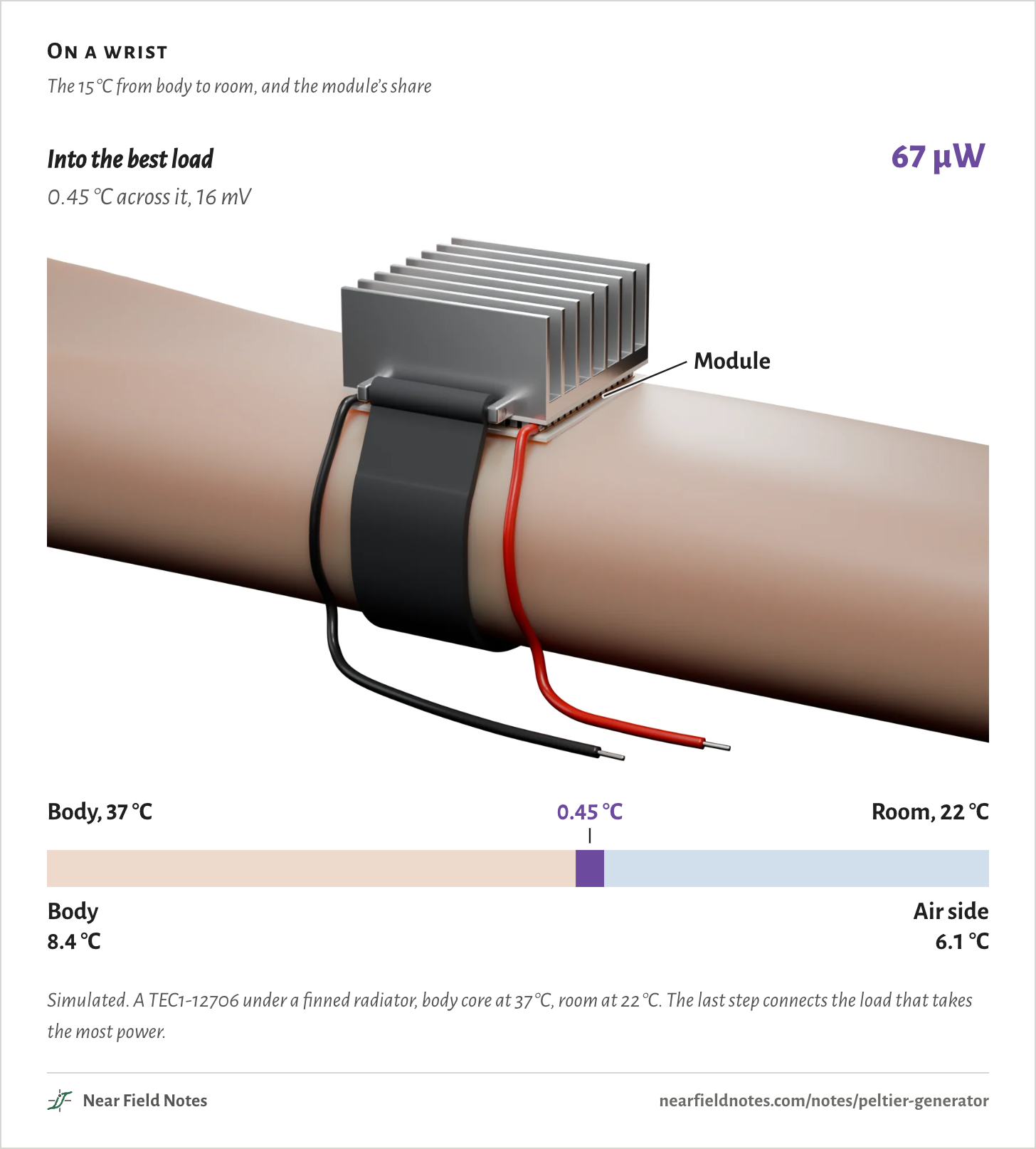
Simulated on a wrist, with 15 °C between body and room, the module gets only 0.58 °C of it and makes 32 mV with nothing connected, or 67 µW into the best load. Clamped between blocks at its 80 °C rating, it makes 0.75 W, from 37.4 W of heat going through it.
Run backward, a Peltier cooler is a voltage source: 49 mV for each degree between its blocks, behind about 2 Ω.
What limits it is how much of the temperature difference it gets. On a wrist, the body and the air take nearly all of it.
On a wrist
The 15 °C from body to room, and the module’s share
Simulated. A TEC1-12706 under a finned radiator, body core at 37 °C, room at 22 °C. The last step connects the load that takes the most power.
A Peltier module is a grid of small legs between two ceramic faces. Run a current through it and it pumps heat from one face to the other. That is how it works as a cooler.
Hold its two faces at different temperatures instead, and it makes a voltage. That is a thermoelectric generator.
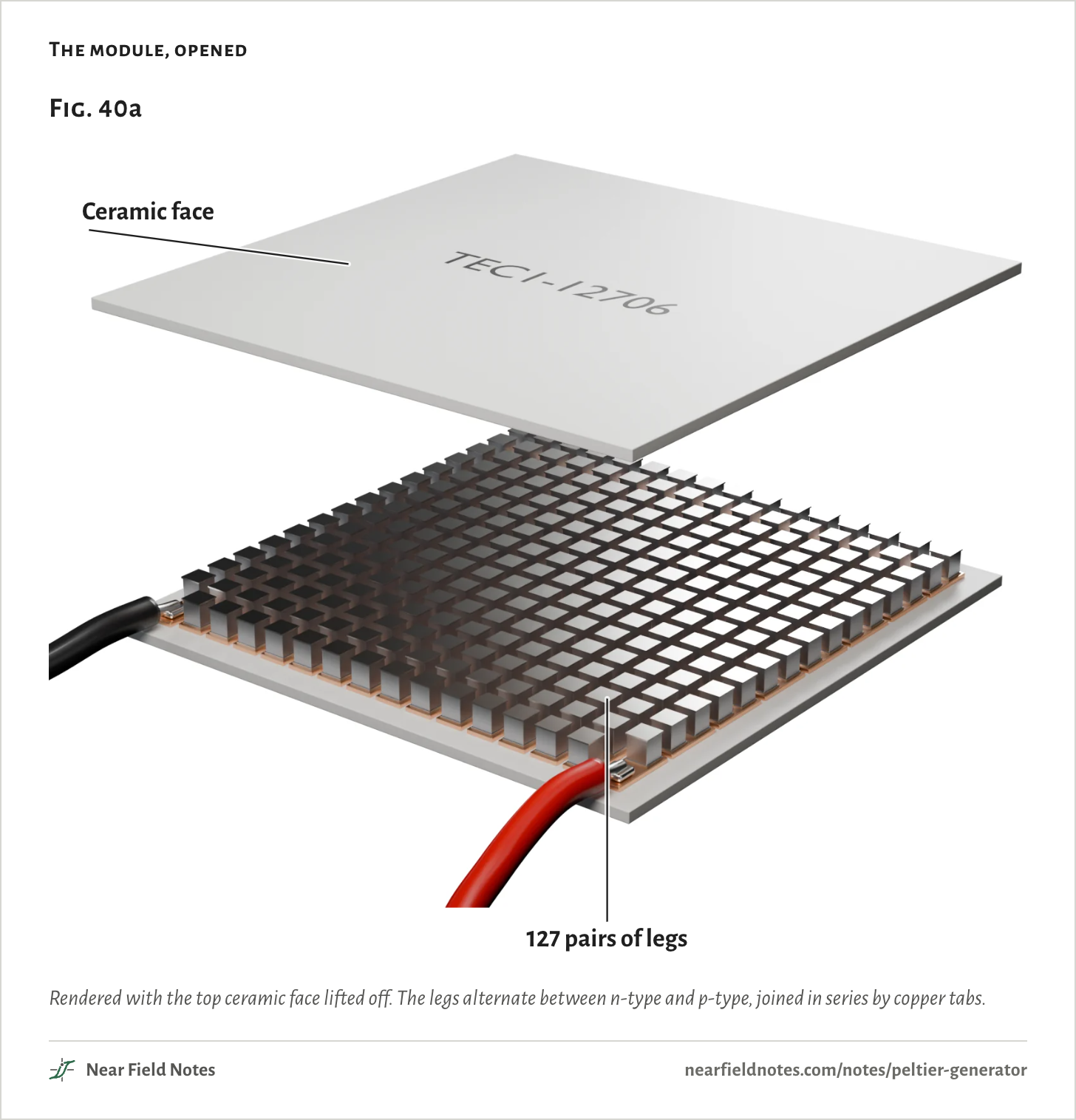
This one is the TEC1-12706, the common 40 mm cooler, with 127 pairs of legs.
The module, opened
Rendered with the top ceramic face lifted off. The legs alternate between n-type and p-type, joined in series by copper tabs.
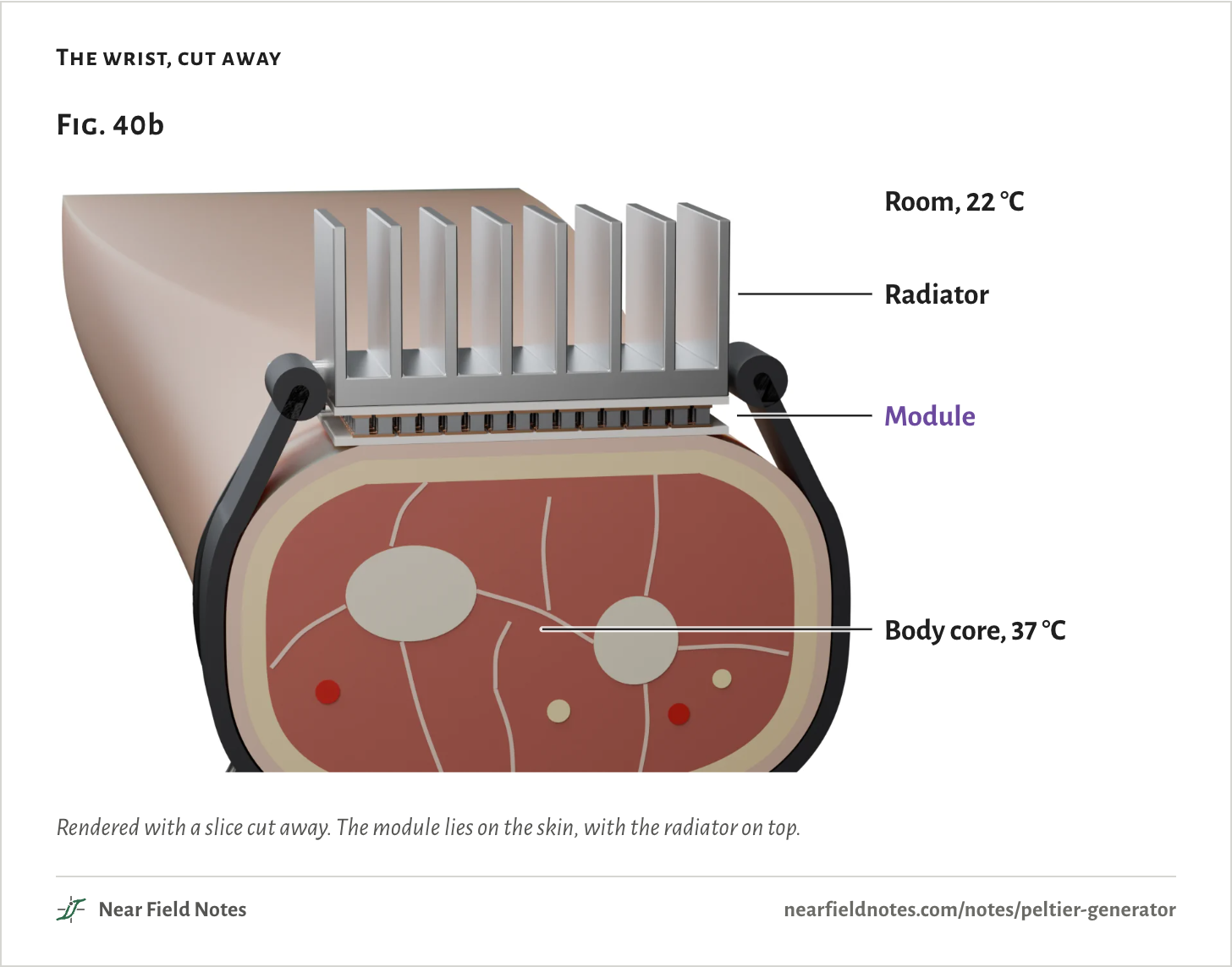
Strap it to the outside of a wrist, under a small finned radiator. The body’s core is at 37 °C and the room at 22 °C, so 15 °C sits between them.
Heat leaves the body through the skin, the module and the radiator, one after another, and out into the room.
The wrist, cut away
Rendered with a slice cut away. The module lies on the skin, with the radiator on top.
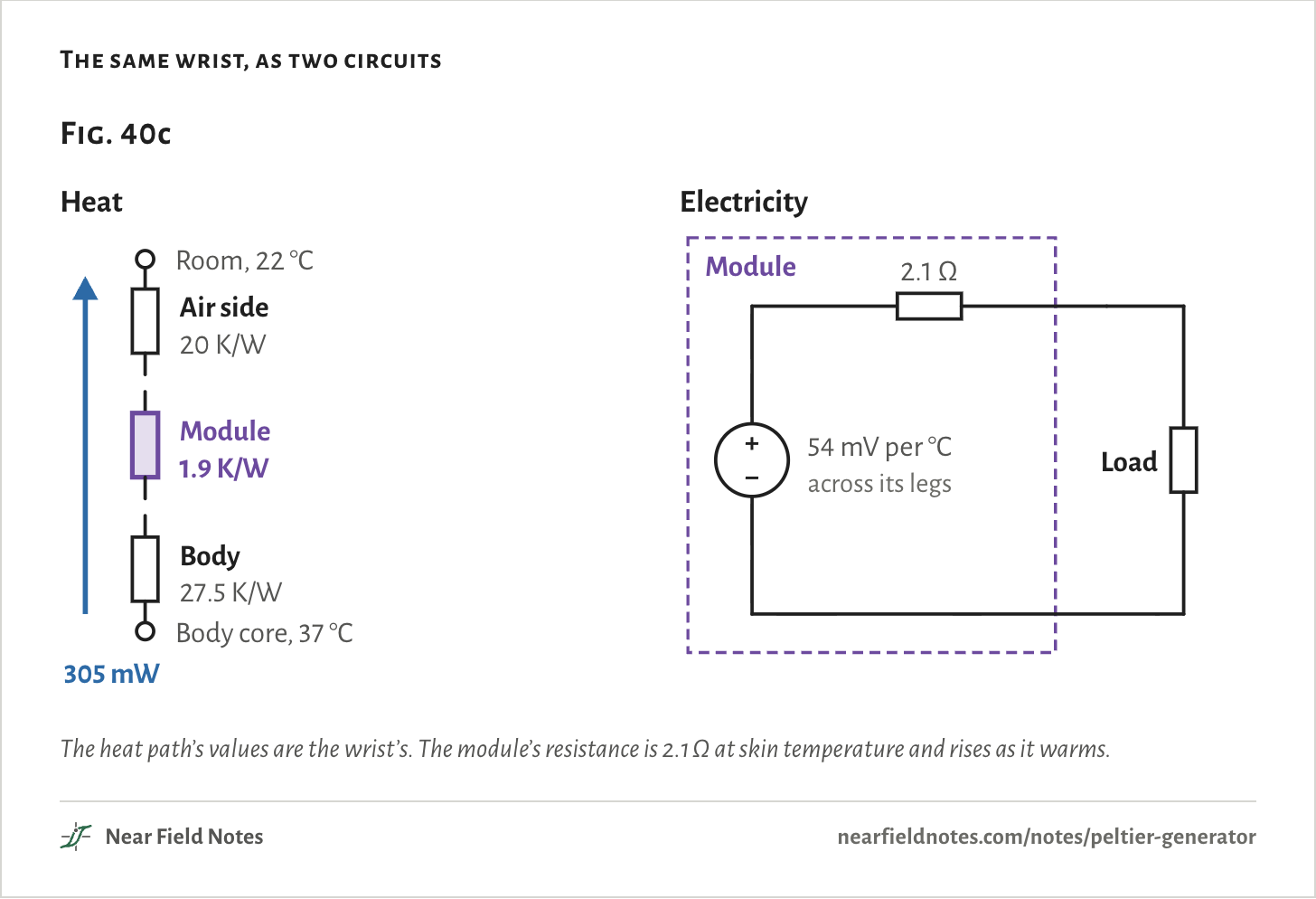
Heat through a stack like that behaves like current through resistors in series, with temperature in place of voltage.
Under the module’s 16 cm², the body is 27.5 K/W, from Leonov’s measurements on the outer wrist. The radiator’s air side is 20 K/W. The module itself is only 1.9 K/W.
Electrically, the module is a voltage source behind its own resistance: 54 mV for each degree across its legs, behind 2.1 Ω.
The same wrist, as two circuits
The heat path’s values are the wrist’s. The module’s resistance is 2.1 Ω at skin temperature and rises as it warms.
A cooler run backward
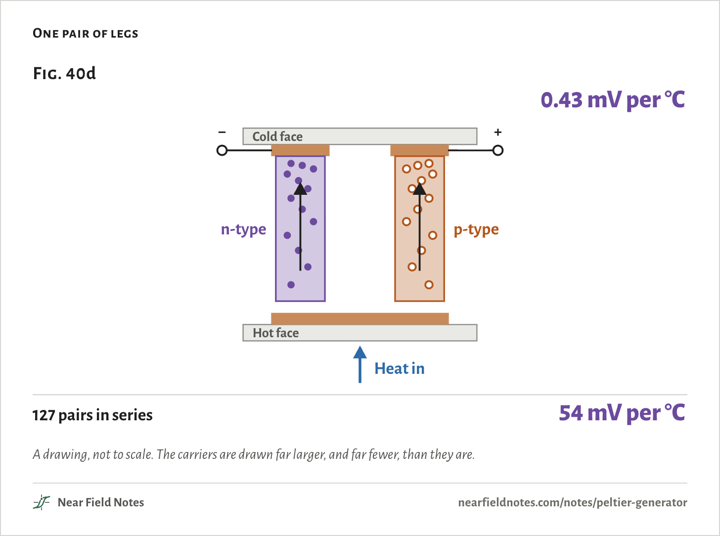
54 mV per °C across the legs
Warm one face and the charge carriers in the legs move faster at that end. More of them drift toward the cold end than drift back, and they crowd there.
In the n-type legs the carriers are electrons, so the cold end goes negative. In the p-type legs they are holes, so it goes positive. That is the Seebeck effect, the cooler’s Peltier effect run the other way.
Each pair gives 0.43 mV for each degree across it. The 127 pairs are in series, so the module gives 54 mV per degree.
One pair of legs
A drawing, not to scale. The carriers are drawn far larger, and far fewer, than they are.
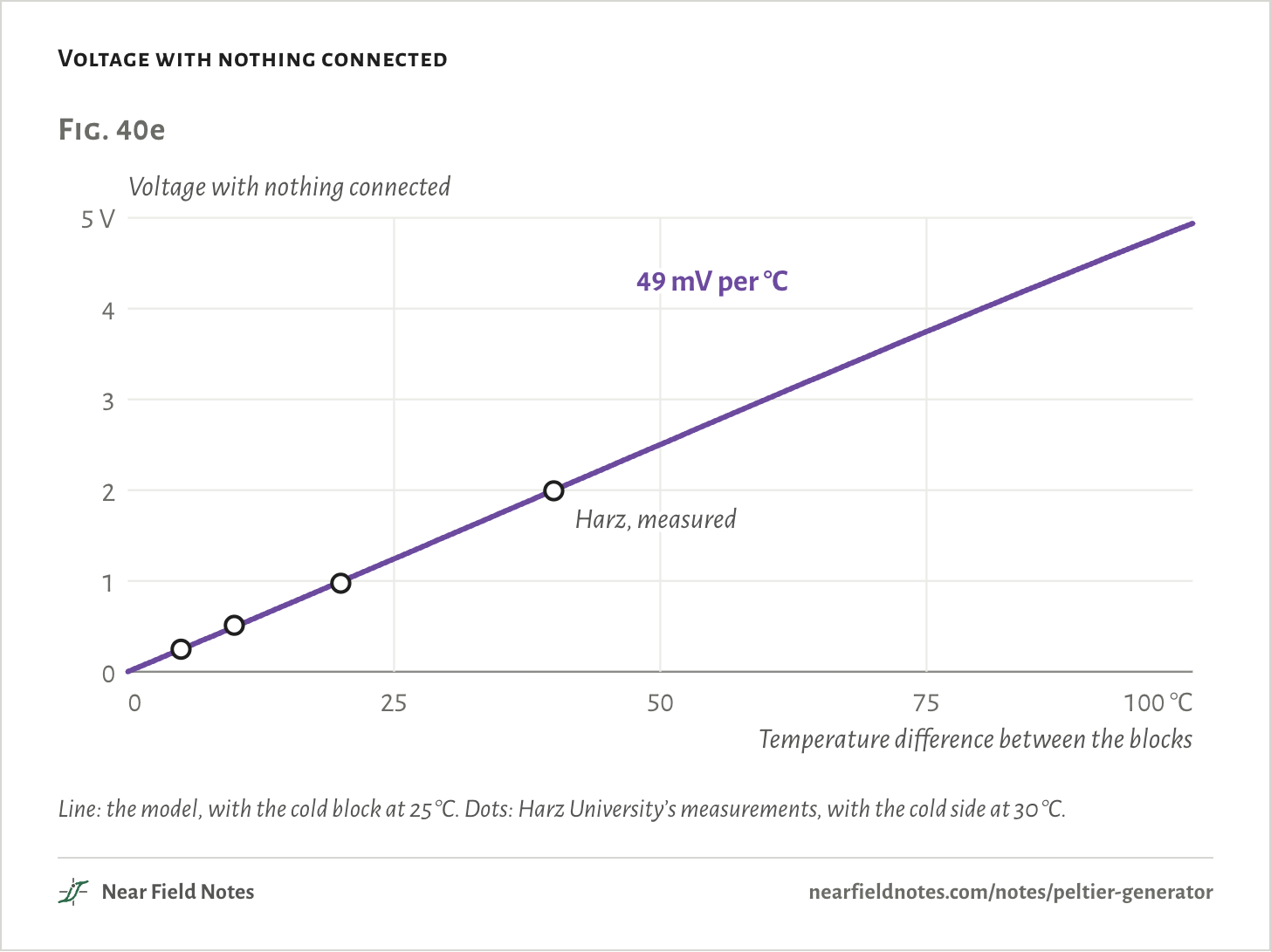
On a bench the module sits clamped between two blocks. The joint on each face, grease and ceramic, takes a little of the difference, so between the blocks it reads 49 mV per degree. Harz University measured 49 to 51.
Its resistance is 2.05 Ω at room temperature and 2.33 Ω with 55 °C across it. The legs’ resistance rises as they warm.
The model behind this page is a cooler model of this module, fitted to its datasheet and run backward. One more number is fitted to a bench: 0.10 K/W for the joint on each face. Its voltages land within 2% of Harz’s four measurements.
Voltage with nothing connected
Line: the model, with the cold block at 25 °C. Dots: Harz University’s measurements, with the cold side at 30 °C.The numbers
Harz’s cold side was at 30 °C; the model is run at their temperatures. The line on the chart has its cold block at 25 °C.
Between the blocks
Harz, measured
Model
Model without the joints
Harz, resistance
40 °C
1.994 V
2.005 V
2.239 V
2.66 Ω
20 °C
0.975 V
0.997 V
1.109 V
2.52 Ω
10 °C
0.512 V
0.496 V
0.551 V
2.50 Ω
5 °C
0.248 V
0.247 V
0.275 V
2.30 Ω
At its 80 °C rating
0.75 W from 37.4 W of heat
Makers rate a standard cooler like this one for 80 °C. The solder inside melts at 138 °C.
So put its hot face against a block held at 80 °C, and its cold face against one held at 25 °C. That is 55 °C across, the most it is rated for with its cold side near room temperature.
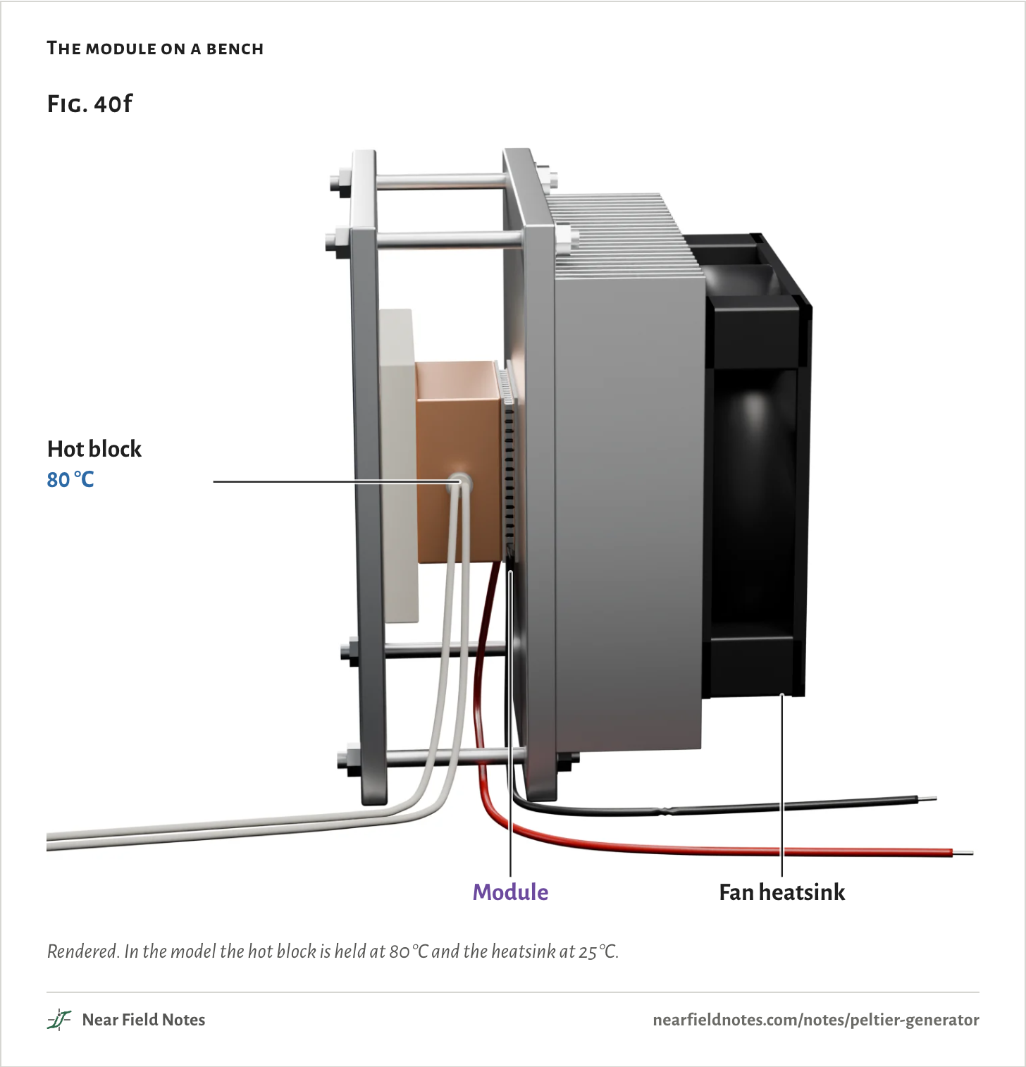
The module on a bench
Rendered. In the model the hot block is held at 80 °C and the heatsink at 25 °C.
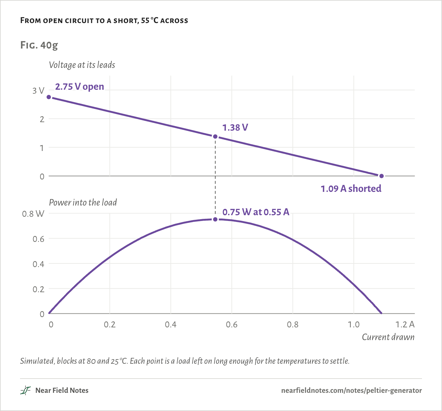
With nothing connected the module reads 2.75 V. Drawing current pulls the voltage down almost in a straight line, to nothing at 1.09 A shorted.
Power peaks at 0.75 W, at 1.38 V and 0.55 A, half the open-circuit voltage. The load is then 2.52 Ω, 1.08 times the module’s own resistance.
From open circuit to a short, 55 °C across
Simulated, blocks at 80 and 25 °C. Each point is a load left on long enough for the temperatures to settle.
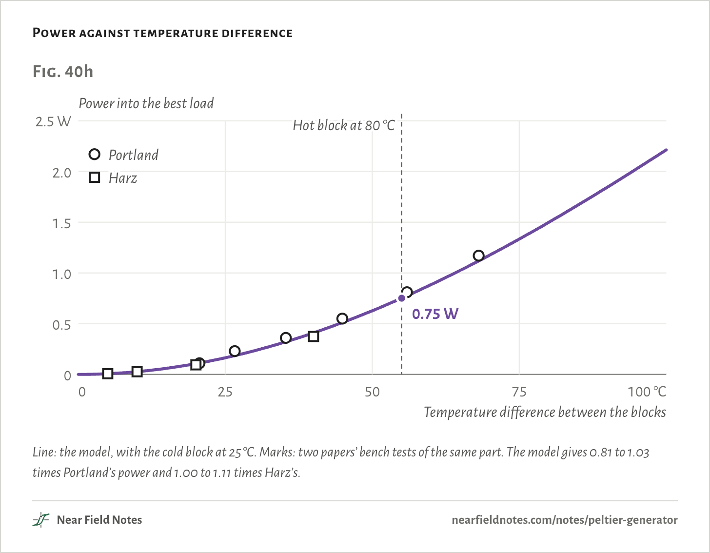
Power against temperature difference
Line: the model, with the cold block at 25 °C. Marks: two papers’ bench tests of the same part. The model gives 0.81 to 1.03 times Portland’s power and 1.00 to 1.11 times Harz’s.The numbers
The model is run at each paper’s own temperatures and load. Harz’s power is at a load equal to the resistance they measured.
Test
Measured
Model
Model over measured
Portland, 20.6 °C
0.11 W
0.11 W
1.03
Portland, 26.6 °C
0.23 W
0.19 W
0.81
Portland, 35.3 °C
0.36 W
0.32 W
0.90
Portland, 44.9 °C
0.55 W
0.52 W
0.94
Portland, 55.9 °C
0.81 W
0.78 W
0.97
Portland, 68.1 °C
1.17 W
1.13 W
0.97
Harz, 40 °C
0.373 W
0.403 W
1.08
Harz, 20 °C
0.094 W
0.104 W
1.11
Harz, 10 °C
0.026 W
0.026 W
1.01
Harz, 5 °C
0.007 W
0.007 W
1.00
628
Stock module at its rating
0.75 W with 55 °C across
Field marks. Hot block at 80 °C, cold side at 25 °C: 2.75 V with nothing connected, and 0.75 W into a 2.52 Ω load.
Look-alike. A generator module. It makes power the same way, but it is built for a hot side of 200 °C and more, with solder to match.
Range. Power grows as the square of the difference: 0.11 W at 20 °C and 2.2 W at 100 °C. But 100 °C across means a 125 °C hot block, 45 °C past the rating and 13 °C short of the solder’s melting point.
Habitat. Warm surfaces under 80 °C. On an 80 °C surface with a fan heatsink it gets 39 °C of the 55 °C and makes 0.51 W. On a plain heatsink, 0.17 W.
629
Where the heat goes
2.0% comes out as electricity
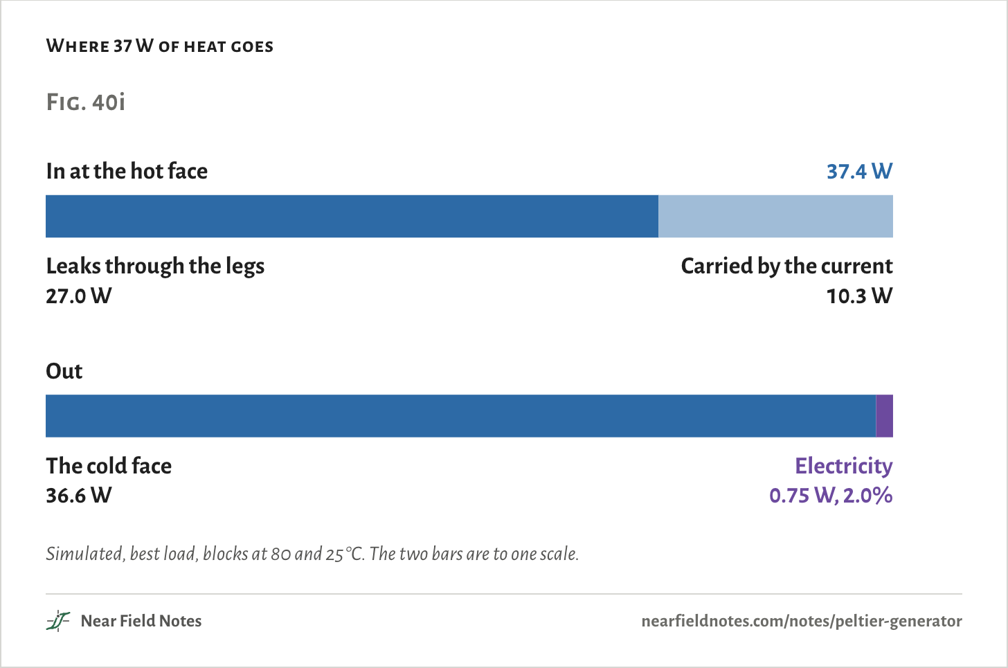
At the best load, 37.4 W of heat goes in at the hot face. Only 0.75 W comes out as electricity, 2.0%.
Most of the heat simply leaks through the legs, 27.0 W of it. The current carries another 10.3 W across.
These are the cooler’s two costs from Note 39 again. The legs conduct heat whether or not they make power, and their resistance turns some of the current back into heat.
Where 37 W of heat goes
Simulated, best load, blocks at 80 and 25 °C. The two bars are to one scale.The numbers
Best load, blocks at 80 and 25 °C, the legs at 76.1 and 28.8 °C. S is the module’s Seebeck coefficient, K its legs’ conductance.
Heat
Leaks through the legs, K ΔT
27.0 W
Carried by the current, SITh
10.7 W
Half the legs’ own heat, back to the hot face
−0.35 W
In at the hot face
37.4 W
Out the cold face
36.6 W
Out as electricity
0.75 W
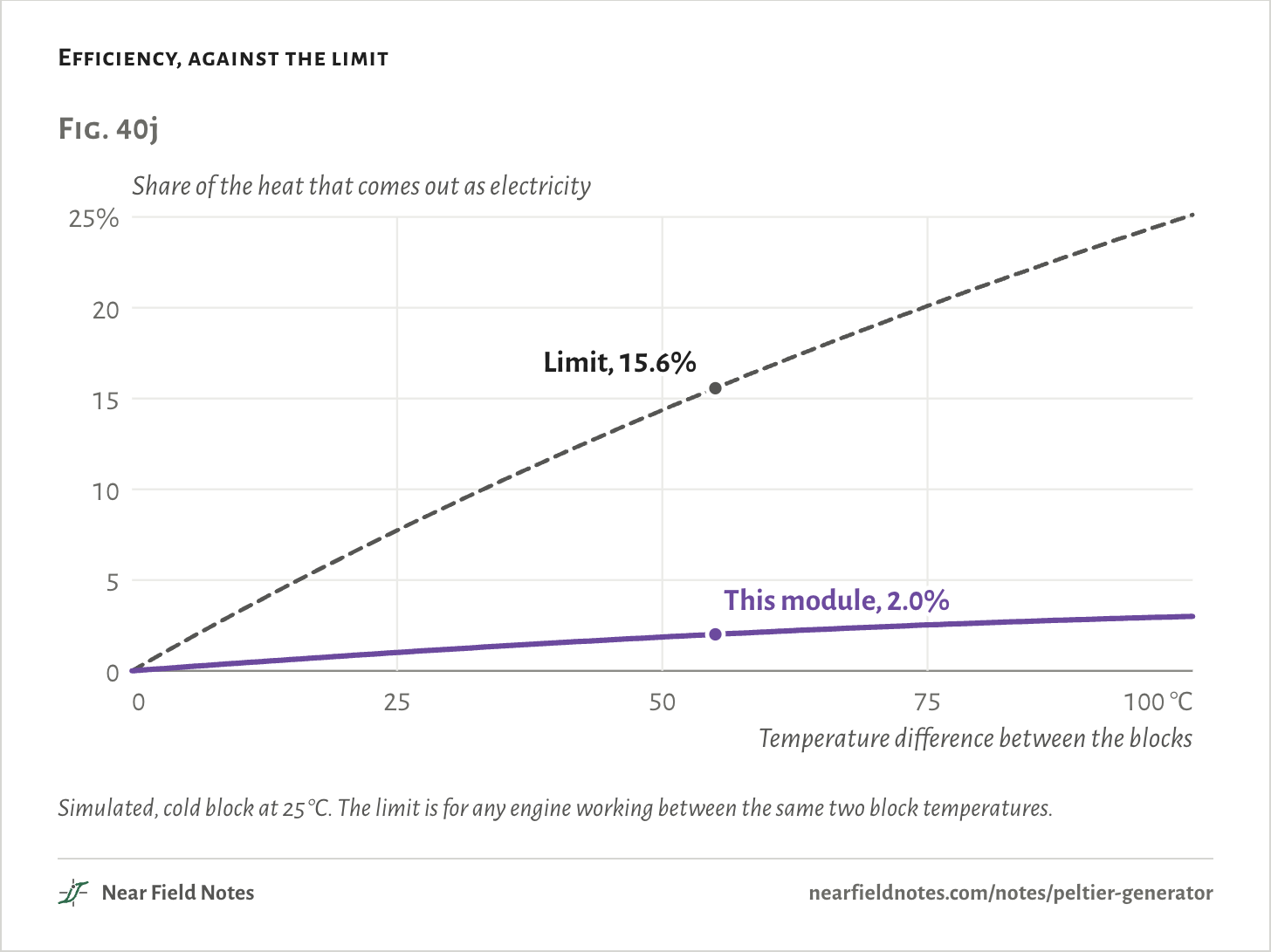
No heat engine can beat the Carnot limit: the temperature difference over the hot side’s absolute temperature. Between 80 and 25 °C that is 15.6%.
The module gets about an eighth of it. The textbook formula for a generator’s best efficiency, with the module’s figure of merit, ZT, of 0.77, gives 2.03%, against the model’s 2.01%.
Hotter only helps so far. At 100 °C across it would reach 3.0%.
Efficiency, against the limit
Simulated, cold block at 25 °C. The limit is for any engine working between the same two block temperatures.The numbers
The limit is the Carnot efficiency, the temperature difference over the hot block’s absolute temperature.
Between the blocks
This module
Limit
Share of the limit
10 °C
0.42%
3.2%
13%
20 °C
0.82%
6.3%
13%
40 °C
1.54%
11.8%
13%
55 °C
2.01%
15.6%
13%
80 °C
2.64%
21.2%
12%
100 °C
3.00%
25.1%
12%
Drawing current brakes it
28 W, 37 W and 46 W
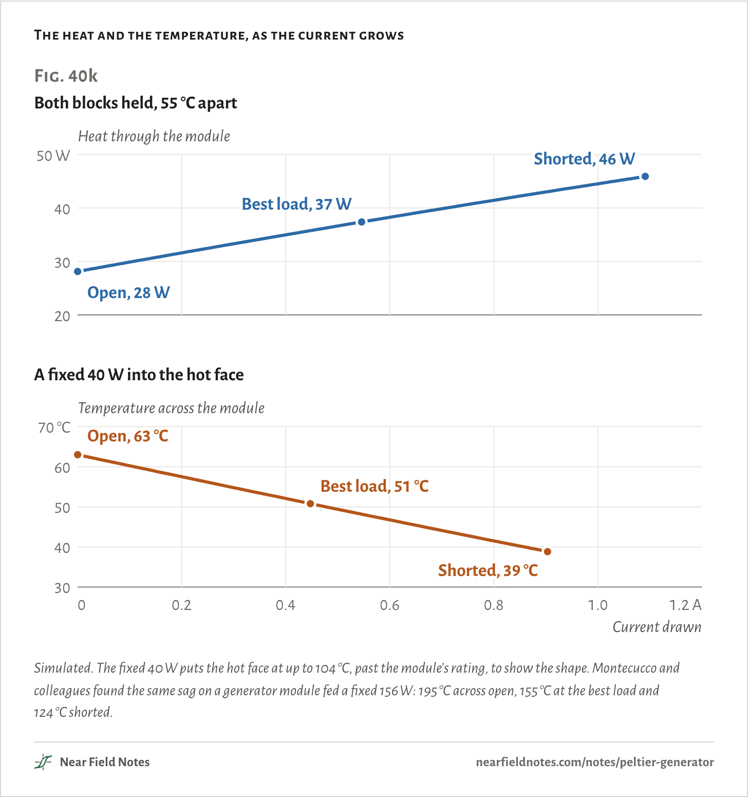
Drawing current makes the module carry more heat. With both blocks held 55 °C apart, 28 W goes through it open, 37 W at the best load and 46 W shorted.
The current carries heat from the hot face to the cold one, as it did in the cooler, and here that is the way the heat already flows. A motor turned as a generator does the same thing: draw current and its shaft gets harder to turn.
Where nothing holds the hot side, that extra heat flow cools it. With a fixed 40 W into the hot face and a fan heatsink on the other, the temperature across the module falls from 63 °C open to 51 °C at the best load and 39 °C shorted.
The heat and the temperature, as the current grows
Simulated. The fixed 40 W puts the hot face at up to 104 °C, past the module’s rating, to show the shape. Montecucco and colleagues found the same sag on a generator module fed a fixed 156 W: 195 °C across open, 155 °C at the best load and 124 °C shorted.
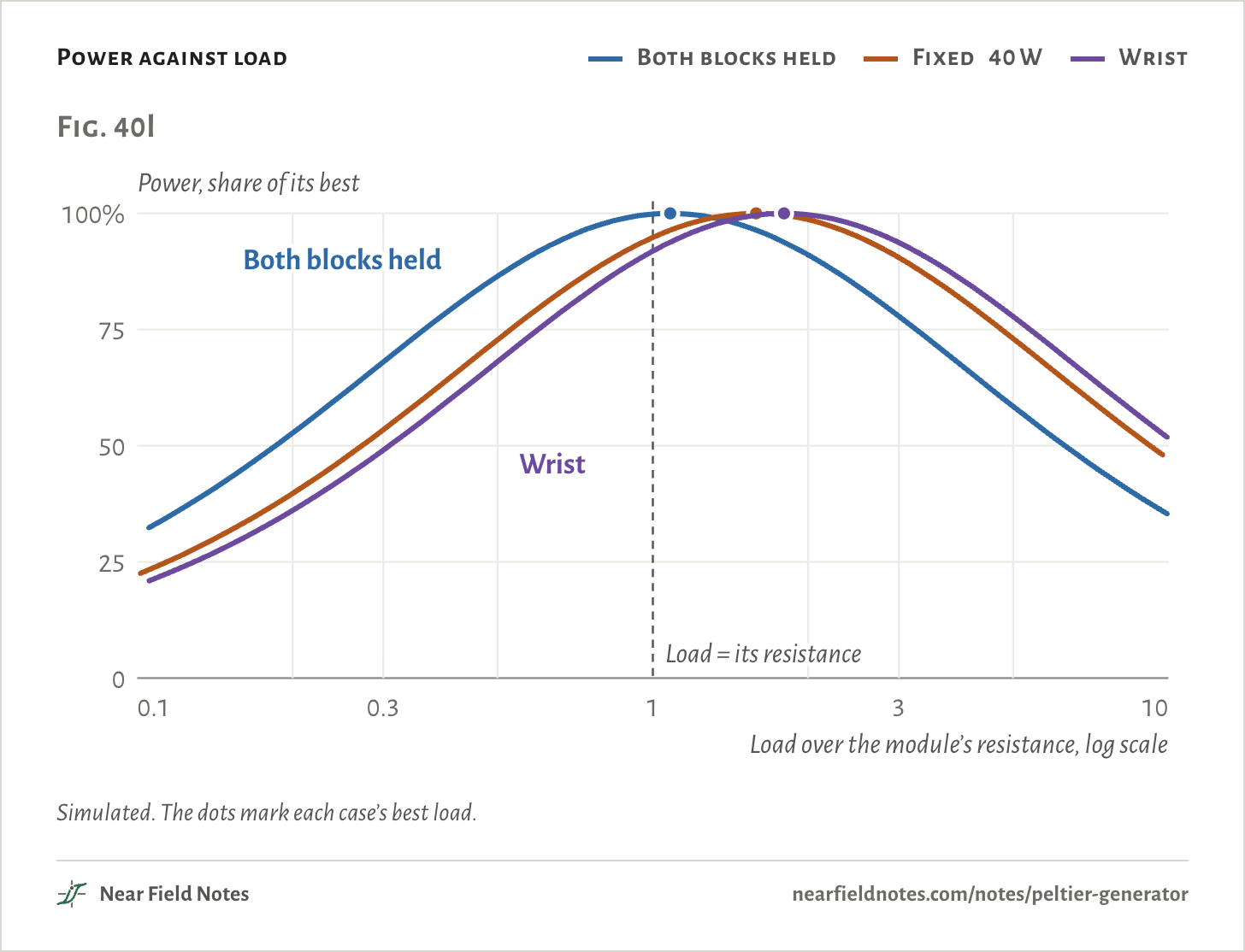
So where the heat is fixed, the best load moves up. Held blocks want 1.08 times the module’s resistance. The fixed 40 W wants 1.59, and the wrist 1.80.
A load equal to the module’s resistance, the textbook matched load, then gives up 5% and 8% of the power. In all three cases the best point sits at half the voltage the module settles to with nothing connected.
Harvester chips work from the open-circuit voltage too. TI’s BQ25504 stops drawing for 256 ms every 16 s to sample it, then holds the module at a set share of it, typically 50% for a thermoelectric harvester. A quarter of a second is too short for the temperatures to settle, so where the heat is fixed it draws a little more current than the best. Montecucco and colleagues found that costs 2.9% of the power.
Power against load
Both blocks held
Fixed 40 W
Wrist
Simulated. The dots mark each case’s best load.The numbers
Both blocks held 55 °C apart; a fixed 40 W into the hot face with the fan heatsink on the other; the wrist with the finned radiator.
Heat held by
Best load over its resistance
Best voltage over settled open-circuit
Lost at a load equal to it
Both blocks held
1.08
0.500
0.2%
Fixed 40 W
1.59
0.495
5.2%
Wrist
1.80
0.500
8.1%
Where the 15 °C goes
3% to the module at the best load
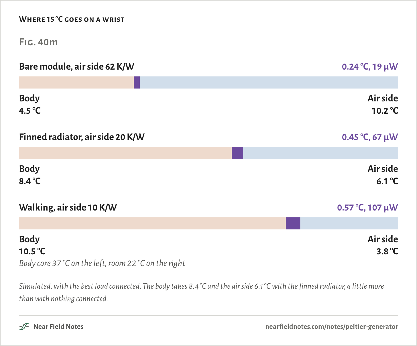
Back on the wrist, the three resistances share the 15 °C in proportion to their size. With nothing connected, the body takes 8.3 °C, the air side 6.0 °C and the module 0.58 °C, which makes 32 mV.
The module is 1.9 K/W against 47.7 K/W for everything else in its path, so it gets only a sliver: about 2.1 mV for each degree between body and room. Connect the best load and its share falls to 0.45 °C, because the current carries heat across it.
A better radiator moves some of the drop onto the module. Bare, it gets 0.24 °C at the best load and makes 19 µW. With the finned radiator, 0.45 °C and 67 µW. Walking, with air moving past the fins, 0.57 °C and 107 µW.
With the finned radiator, 19 mW/cm² of heat flows out through the skin under it, the average Leonov measured on wrists with a radiator.
Where 15 °C goes on a wrist
Simulated, with the best load connected. The body takes 8.4 °C and the air side 6.1 °C with the finned radiator, a little more than with nothing connected.The numbers
Temperatures at the best load. Body 27.5 K/W under the module’s 16 cm².
Air side
Its resistance
Body
Both joints
Module
Air side
Open circuit
Best load
Heat, mW/cm²
Bare module
62 K/W
4.53 °C
0.03 °C
0.24 °C
10.20 °C
17.1 mV
19 µW
10.3
Finned radiator
20 K/W
8.39 °C
0.06 °C
0.45 °C
6.10 °C
31.7 mV
67 µW
19.1
Walking
10 K/W
10.52 °C
0.08 °C
0.57 °C
3.83 °C
39.8 mV
107 µW
23.9
The most power comes when the module’s thermal resistance is about the size of everything else in its path, so that it takes about half the drop. Snyder’s chapter on energy harvesting gives the same rule.
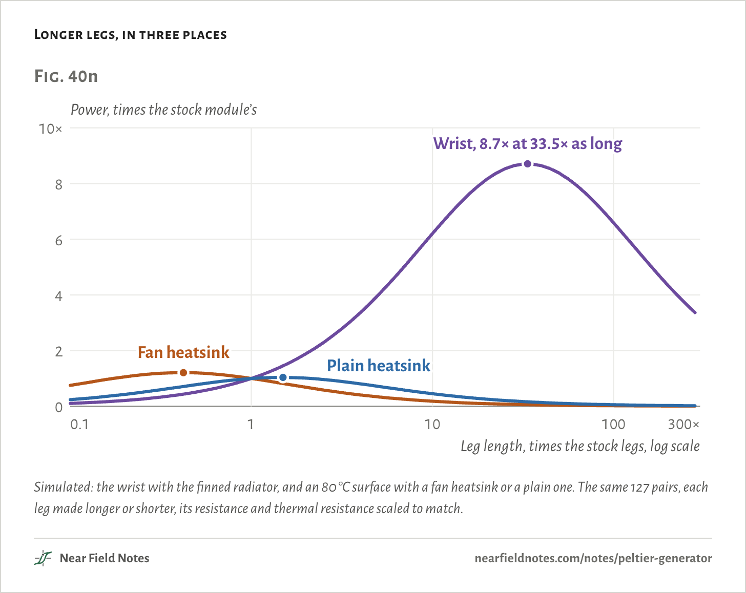
A stock module is far too small a resistance for a wrist. Longer legs make it larger.
Longer legs, in three places
Simulated: the wrist with the finned radiator, and an 80 °C surface with a fan heatsink or a plain one. The same 127 pairs, each leg made longer or shorter, its resistance and thermal resistance scaled to match.The numbers
Longer legs: the same 127 pairs, each leg’s resistance and thermal resistance scaled with its length. The surfaces are held at 80 °C in a 25 °C room.
Where
Everything else in the path
Best legs
Module then
Stock module
Best legs give
Stock’s share of best
Wrist
47.71 K/W
34×
64.21 K/W
67 µW
584 µW
11%
80 °C surface, fan heatsink
0.51 K/W
0.42×
0.71 K/W
0.51 W
0.62 W
83%
80 °C surface, plain heatsink
1.71 K/W
1.5×
2.49 K/W
0.17 W
0.18 W
96%
630
Module with longer legs
8.7 times the power on a wrist
Field marks. With each leg 33.5 times as long, the module rises to 64 K/W, a little more than the rest of the path, and takes 7.5 °C of the 15 °C. It gives 584 µW at 235 mV.
Look-alike. A module built for small temperature differences, like the one in Citizen’s watch: many thin legs, packed tight. That raises its thermal resistance and its voltage per degree together.
Range. Longer legs pay only where the rest of the path is a large resistance. On an 80 °C surface the stock legs already give 83% of the best with a fan heatsink and 96% with a plain one.
Habitat. Body heat. Citizen’s 1999 watch packed 2,268 pairs of legs into about a square centimeter, for 0.8 V per degree. On a wrist it saw about 1.2 °C and made 12 µW on average. A quartz movement needs about 1 µW.
631
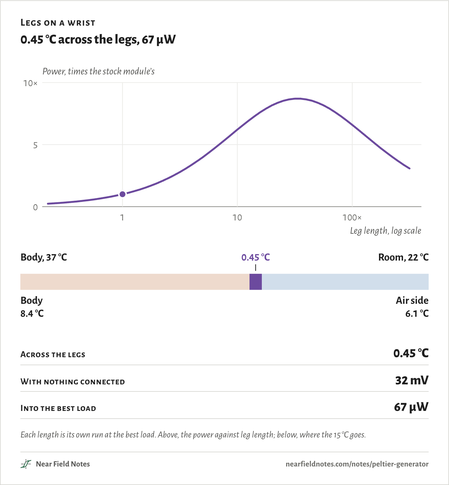
Stretch the legs yourself
0.3 to 300 times as long
Set the legs’ length, on the wrist with the finned radiator. Each length is its own run.
Short legs get almost none of the drop. Very long ones take most of it, but their own resistance eats the power. The best is 33.5 times the stock length.
Legs on a wrist
0.45 °C across the legs, 67 µW
Across the legs
0.45 °C
With nothing connected
32 mV
Into the best load
67 µW
Each length is its own run at the best load. Above, the power against leg length; below, where the 15 °C goes.The numbers
On the wrist with the finned radiator. Temperatures and power at the best load.
A stock module on a wrist makes about 30 mV. An ordinary harvesting boost converter can’t start from that. TI’s BQ25504, BQ25505 and BQ25570 need about 600 mV for a cold start.
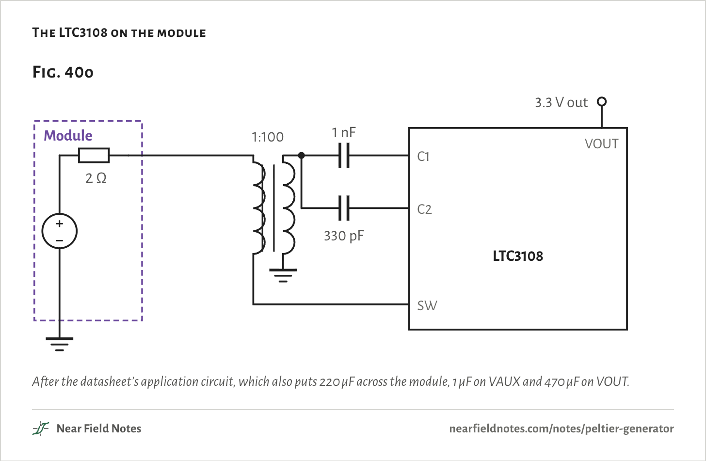
The LTC3108 starts from 20 mV typical, 50 mV at most. Its switch and a 1:100 step-up transformer form an oscillator, with 330 pF from the secondary back to the switch’s gate.
The switch conducts with no voltage on its gate, so current flows in the primary before any supply exists. Chipworks’ teardown found it to be a depletion-mode transistor. The datasheet says only that the chip starts from 20 mV.
The LTC3108 on the module
After the datasheet’s application circuit, which also puts 220 µF across the module, 1 µF on VAUX and 470 µF on VOUT.
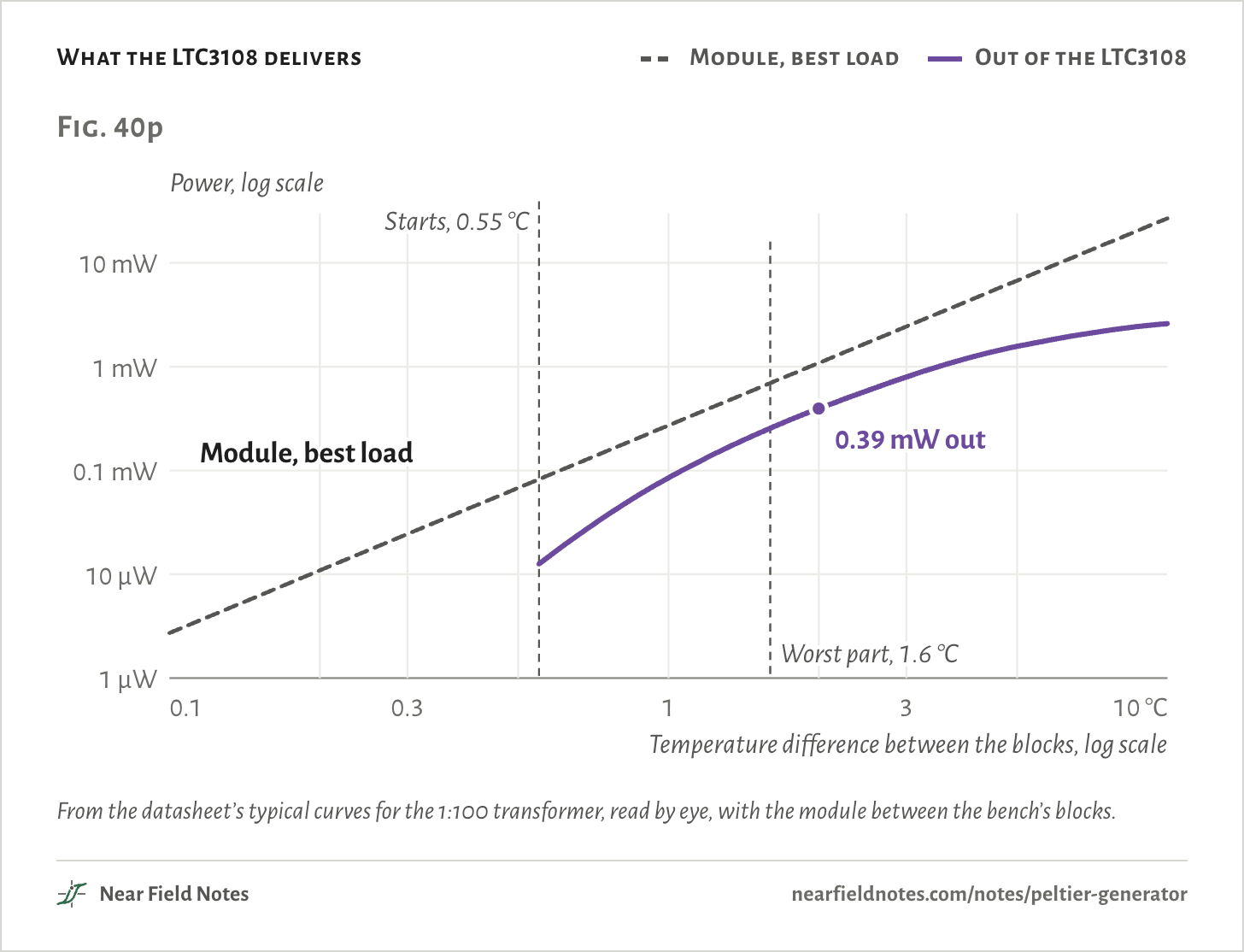
On this module a typical part starts with 0.55 °C between the blocks, 27 mV with nothing connected. A worst-case part needs 1.6 °C. At 2 °C it delivers 0.39 mW of the 1.1 mW the module could give.
On the wrist it only just starts. A typical part sees 20 mV at its pin and delivers 12.6 µW. A worst-case part wouldn’t start.
The 1:100 transformer suits the lowest voltages. At 10 °C it delivers 2.6 mW of 27 mW, and the datasheet points to a lower ratio for higher input voltages.
What the LTC3108 delivers
Module, best load
Out of the LTC3108
From the datasheet’s typical curves for the 1:100 transformer, read by eye, with the module between the bench’s blocks.The numbers
From the datasheet’s typical curves for the 1:100 transformer, read by eye.
Between the blocks
Open circuit
At the chip
Chip’s input resistance
Available
Out of the LTC3108
0.5 °C
24 mV
18 mV
6.5 Ω
68 µW
Doesn’t start
1.0 °C
48 mV
34 mV
5.0 Ω
272 µW
85 µW
2.0 °C
95 mV
60 mV
3.6 Ω
1.1 mW
394 µW
5.0 °C
238 mV
132 mV
2.6 Ω
6.8 mW
1.6 mW
10.0 °C
476 mV
264 mV
2.6 Ω
27 mW
2.6 mW
Where it wins
A few percent
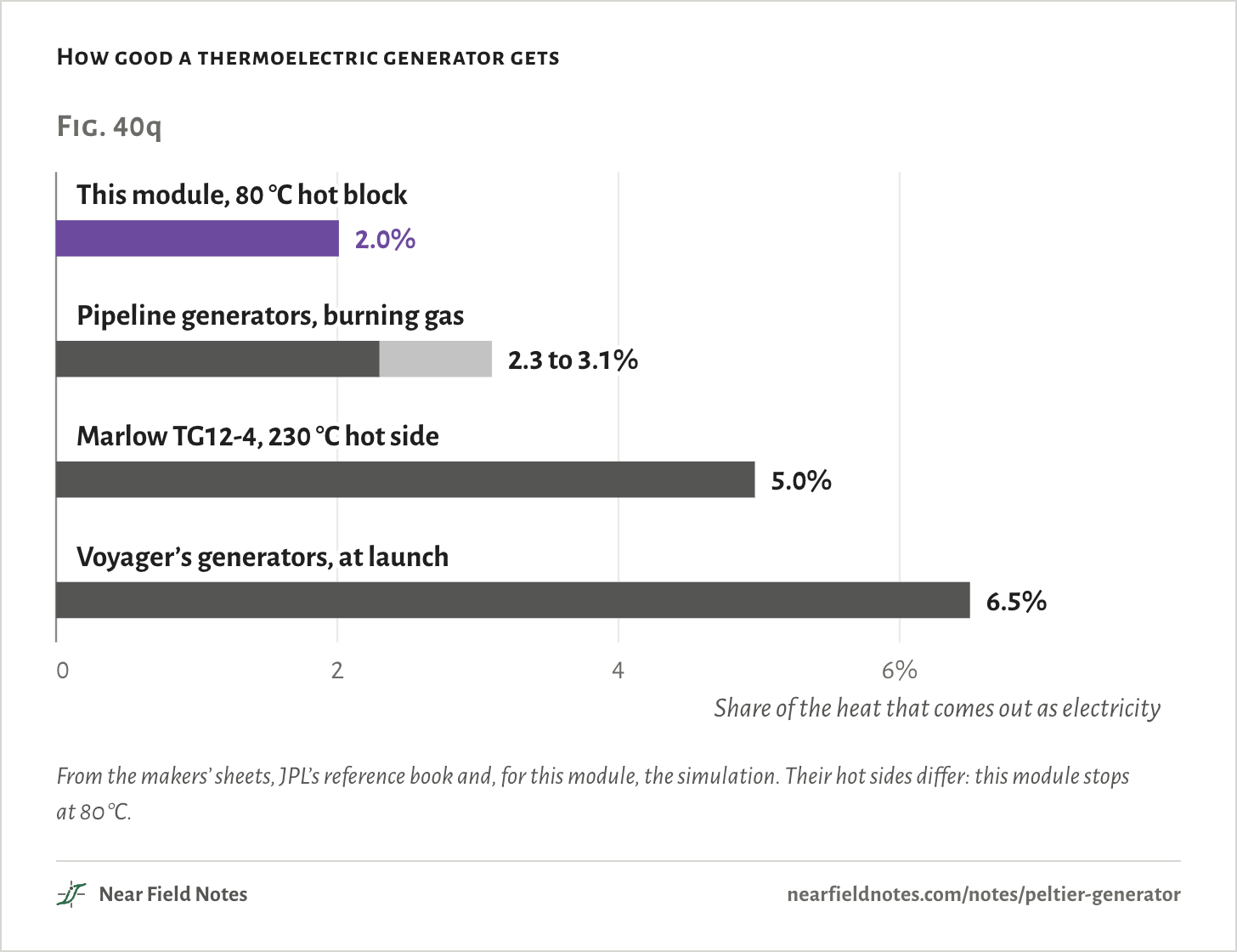
A few percent is as good as a thermoelectric generator gets. Marlow’s TG12-4, a module built as a generator, reaches 4.97% with its hot side at 230 °C.
So they win where nothing else can run. More than 35,000 burn gas along pipelines and at wellheads, turning 2.3 to 3.1% of the fuel’s heat into electricity. A review by Da Lio and Lazzaretto gives them 20 years of life.
Voyager 1 left in 1977 with three radioisotope generators making 470 W between them, at 6.5%. By 2023 NASA put it at 225 W.
How good a thermoelectric generator gets
From the makers’ sheets, JPL’s reference book and, for this module, the simulation. Their hot sides differ: this module stops at 80 °C.
Will a stock module do?
Three questions
It comes down to how much of the temperature difference the module gets, how hot its hot side runs, and how many millivolts it makes.
Key to a Peltier module as a generator
What sets its power, and what reads it?
1aLarge heatsinks or blocks on both facesGo to 2
1bSkin, still air or a small radiator in the heat’s pathGo to 3
2aThe hot side stays under 80 °CStock module, loaded at 1.1 to 1.6 times its resistance
2bThe hot side runs hotterA generator module rated for it
3aTens of millivolts from the moduleLTC3108 with a 1:100 transformer, or legs made for it
3bMore than about 0.6 VA harvesting boost converter held at half the open-circuit voltage
A cooler’s solder melts at 138 °C, and generator modules are built for 200 °C and more. The bench in Fig. 40f ends at 2a, and the wrist in Fig. 40b at 3a.
Conditions
Simulated
Every voltage, power, heat flow and temperature on this page comes from a model of the module, checked against two published bench tests of the same part. None was measured on a bench for this page.
Module
TEC1-12706, 127 pairs. A standard cooler model, fitted to its datasheet, with Ferrotec’s curves for how the legs’ properties change above room temperature. One fitted number: 0.10 K/W for the joint on each face, grease and ceramic. “Across the legs” leaves those joints out; they take 0.03 °C each on the wrist.
Check
Harz University, 2024: voltage within 2% of four points from 5 to 40 °C, and power 1.00 to 1.11 times theirs. University of Portland, 2012: power 0.81 to 1.03 times theirs, and 2.41% efficiency against their 2.22% at 68.1 °C, which counts the heater’s whole power. Without the joints the model reads 12% high on voltage.
Bench
Blocks held at 80 and 25 °C unless a figure says otherwise. The fixed-heat case puts 40 W into the hot face, with a 0.30 K/W fan heatsink on the cold face in a 25 °C room. The hot surfaces are held at 80 °C, with the same fan heatsink or a 1.5 K/W plain one.
Wrist
Body core 37 °C, room 22 °C. The body under the module’s 16 cm²: 27.5 K/W, from Leonov’s 440 cm²·K/W for the outer wrist. The air side: 62 K/W bare, 20 K/W with the finned radiator, 10 K/W walking.
LTC3108
Its input resistance and efficiency against input voltage, read by eye from the datasheet’s typical curves for the 1:100 transformer. It starts at 20 mV on its pin, typical, or 50 mV worst case.
Render
Blender. The wrist and the bench are drawn for this page.
Model results, checked against published bench tests. Nothing on this page was measured on a bench for it.
Limits
The joint resistance is fitted to Harz’s bench. A different clamp, grease or block would give a different number, and every bench figure moves with it.
Ferrotec’s curves come from a 71-pair module, scaled to this one at room temperature. The datasheet gives 2.0 Ω ±10% for the TEC1-12706, and Harz measured 2.3 to 2.7 Ω on theirs.
The fixed 40 W case runs the hot face past the 80 °C rating, up to 104 °C with nothing connected. It is there for the shape, not as a way to run the part.
The wrist uses one body resistance, Leonov’s average, and still air values for each radiator. Real skin changes with blood flow, the room and the person.
Longer legs keep the same material, count and faces. A real harvesting module also changes the legs’ area, how tightly they pack, and its faces.
The LTC3108 curves are read by eye, and its start points are the datasheet’s typical and worst-case values only.
The pipeline, Marlow and Voyager efficiencies are their makers’ and operators’ published numbers, at hot sides far above this module’s.
Files
sim/teg.pyThe module as a generator, the check against the two papers, the bench, the hot surfaces, the fixed heat, the wrist, longer legs and the LTC3108
sim/site.pyThe heat taken apart, every interface on the wrist, power against load and the leg lengths of the explorer
render/wrist.pyThe wrist and its cutaway in Blender