Near Field Notes

Note 27Signal integrityRev 1Watch the video · 0:10

Car camera coax

How does one coax carry a car camera’s video, control and power?

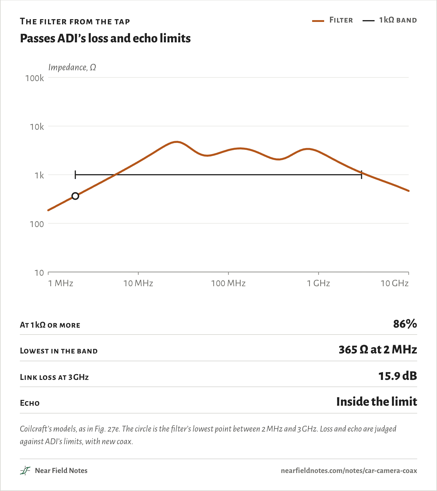
Power rides along as DC, and the data rides on top of it in both directions at once. Four coils keep the data out of the 12 V supply, and each chip subtracts its own signal to hear the other end. On Antmicro’s GMSL2 boards the coils hold 1 kΩ or more over 86% of the band ADI recommends, and over 15 m of coax the video loses 15.9 dB at 3 GHz, where ADI allows 21.1 dB.

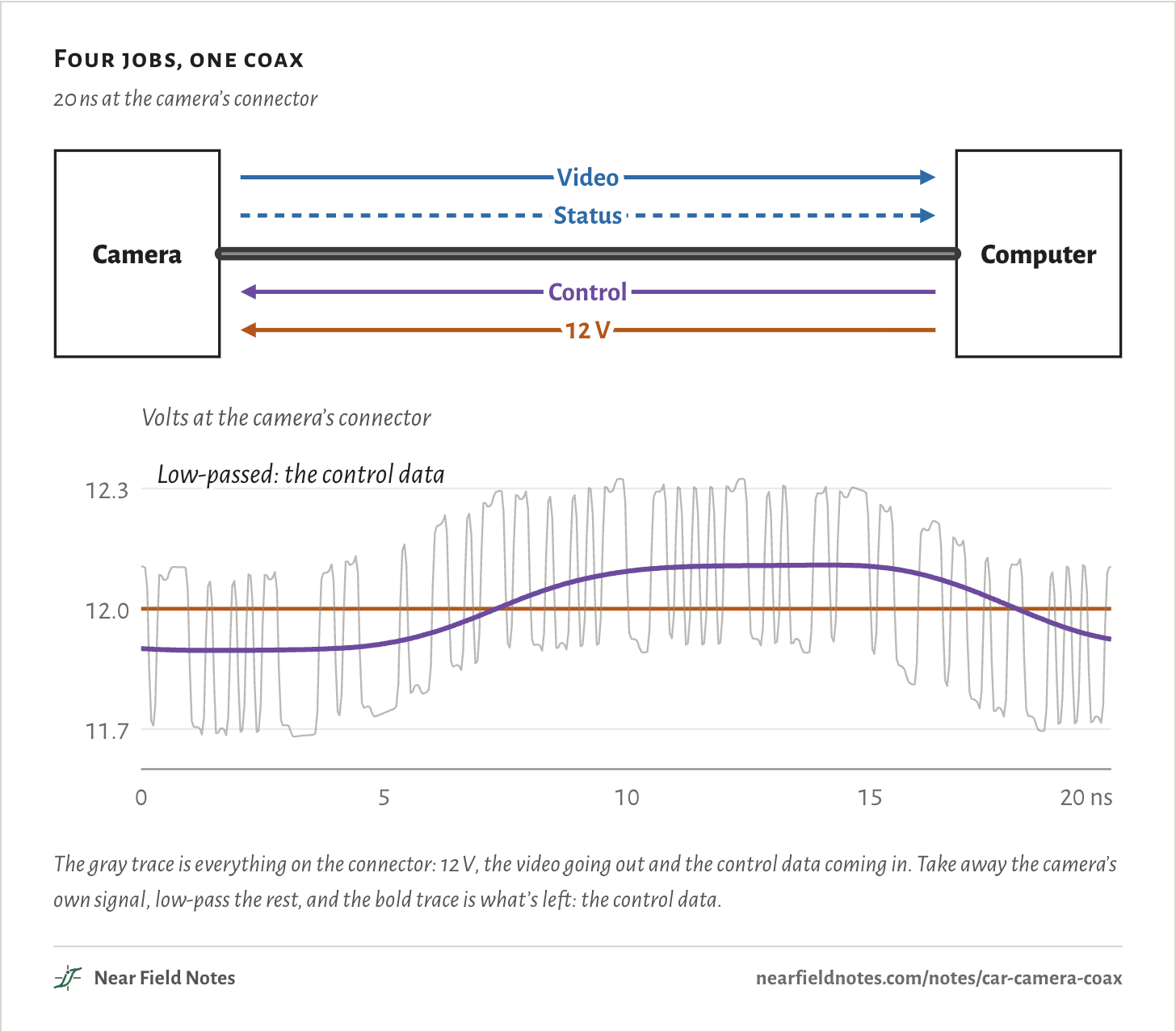
The camera sends 6 Gb/s of video and its status replies. The computer sends back control data at 187.5 Mb/s, and 12 V to run the camera. The shield is the ground for all of it.

The figure is 20 ns of the voltage at the camera’s end of the coax.

Four jobs, one coax

20 ns at the camera’s connector

CameraComputerVideoStatusControl12 VVolts at the camera’s connector11.712.012.305101520 nsLow-passed: the control dataCameraComputerVideoStatusControl12 VVolts at the camera’s connector11.712.012.305101520 nsLow-passed: the control dataCameraComputerVideoStatusControl12 VVolts at the camera’s connector11.712.012.305101520 nsLow-passed: the control data
The gray trace is everything on the connector: 12 V, the video going out and the control data coming in. Take away the camera’s own signal, low-pass the rest, and the bold trace is what’s left: the control data.
The numbers
Every 1.7 ns of the 20 ns shown. The control data alone is what arrives from the computer, before the camera’s own signal is added.
TimeVideo aloneEverythingCanceled and low-passedControl data alone
0.0 ns12.200 V12.105 V11.901 V11.890 V
1.7 ns11.800 V11.702 V11.896 V11.888 V
3.3 ns11.800 V11.684 V11.898 V11.898 V
5.0 ns11.800 V11.740 V11.913 V11.958 V
6.7 ns12.056 V12.092 V11.969 V12.051 V
8.3 ns12.056 V12.138 V12.048 V12.096 V
10.0 ns11.944 V12.069 V12.093 V12.107 V
11.7 ns12.056 V12.179 V12.106 V12.110 V
13.3 ns11.944 V12.039 V12.108 V12.108 V
15.0 ns11.944 V12.032 V12.106 V12.073 V
16.7 ns12.056 V12.056 V12.064 V11.982 V
18.3 ns11.800 V11.731 V11.984 V11.916 V

Two boards and a coax

Antmicro’s open GMSL2 pair

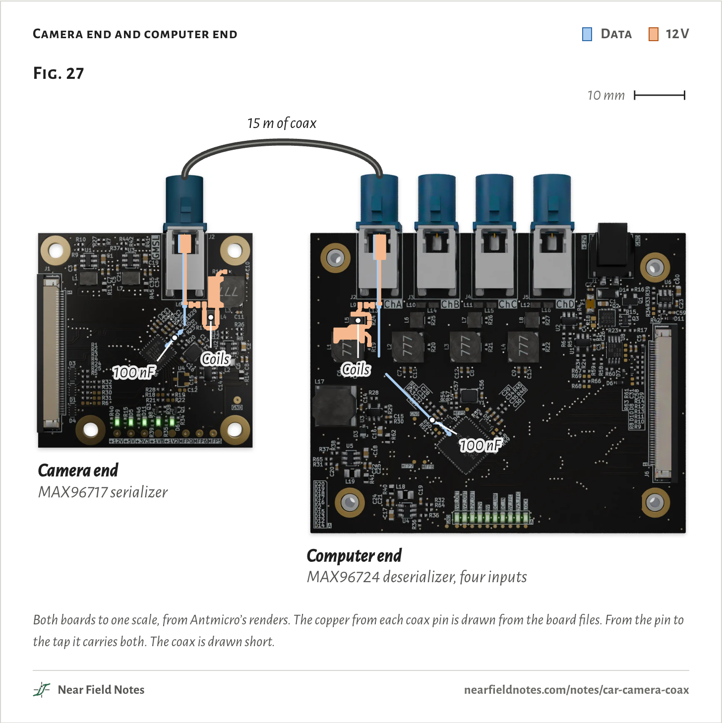
Antmicro publishes both ends of a GMSL2 link as open hardware. The camera end is a 43 mm square board with a MAX96717 serializer. The camera’s MIPI CSI-2 lanes go in, and one coax comes out.

The computer end is 75 by 60 mm, with a MAX96724 deserializer that takes four cameras. Both boards use FAKRA connectors and 50 Ω coax.

On each board the coax’s center pin meets two paths. One goes through a 100 nF capacitor to the chip. The other turns off at a tap into a ladder of four coils that ends at 12 V.

Camera end and computer end
  • Data
  • 12 V
Fig. 2715 m of coaxCamera endMAX96717 serializerComputer endMAX96724 deserializer, four inputs10 mmFig. 2715 m of coaxCamera endMAX96717 serializerComputer endMAX96724 deserializer, four inputs100 nFCoils100 nFCoils10 mmFig. 2715 m of coaxCamera endMAX96717 serializerComputer endMAX96724 deserializer, four inputs100 nFCoils100 nFCoils10 mm
Both boards to one scale, from Antmicro’s renders. The copper from each coax pin is drawn from the board files. From the pin to the tap it carries both. The coax is drawn short.
The numbers
BoardAntmicro designChipCoax connectors
Camera endGMSL Serializer rev 1.1.1, 43 × 43 mm, 4 layersMAX96717J2, one FAKRA
Computer endGMSL Deserializer rev 1.0.3, 75.1 × 60.1 mm, 4 layersMAX96724J2 to J5, four FAKRA

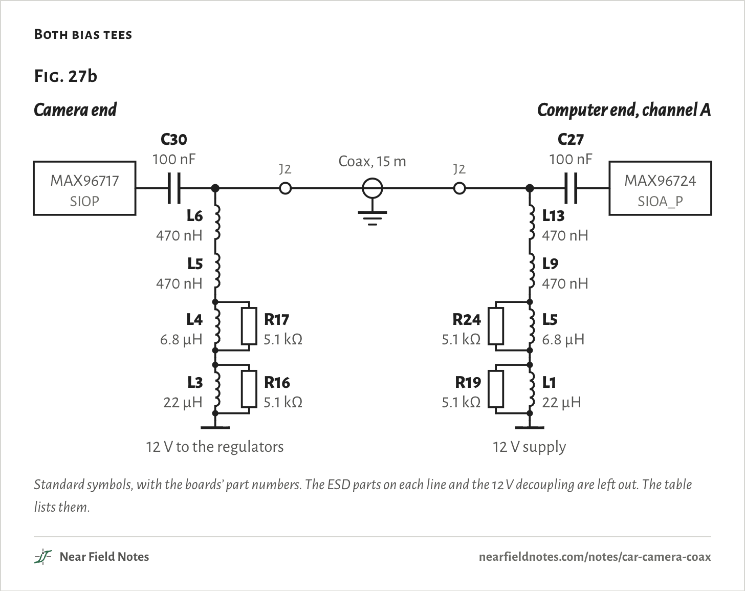
Drawn as a circuit, each end is a bias tee. The capacitor passes the data and blocks the DC. The coils pass the DC and block the data.

The two ends are built the same, part for part. Their coils are filter 14 in ADI’s list of power filters recommended for new GMSL2 designs, and Coilcraft’s reference filter SMD-POC-006.

The computer end puts 12 V onto its coax. The camera end takes it off and feeds its regulators.

Both bias tees
Fig. 27bCamera endMAX96717SIOPC30100 nFJ2L6470 nHL5470 nHR175.1 kΩL46.8 µHR165.1 kΩL322 µH12 V to the regulatorsComputer end, channel AMAX96724SIOA_PC27100 nFJ2L13470 nHL9470 nHR245.1 kΩL56.8 µHR195.1 kΩL122 µH12 V supplyCoax,15 mFig. 27bCamera endMAX96717SIOPC30100 nFJ2L6470 nHL5470 nHR175.1 kΩL46.8 µHR165.1 kΩL322 µH12 V to the regulatorsComputer end, channel AMAX96724SIOA_PC27100 nFJ2L13470 nHL9470 nHR245.1 kΩL56.8 µHR195.1 kΩL122 µH12 V supplyCoax,15 mFig. 27bCamera endMAX96717SIOPC30100 nFJ2L6470 nHL5470 nHR175.1 kΩL46.8 µHR165.1 kΩL322 µH12 V to the regulatorsComputer end, channel AMAX96724SIOA_PC27100 nFJ2L13470 nHL9470 nHR245.1 kΩL56.8 µHR195.1 kΩL122 µH12 V supplyCoax, 15 m
Standard symbols, with the boards’ part numbers. The ESD parts on each line and the 12 V decoupling are left out. The table lists them.
The numbers
PartCamera endComputer end
Coupling capacitorC30, 100 nFC27, 100 nF
470 nH, Coilcraft PFL1609-471L6, L5L13, L9
6.8 µH, Coilcraft 1210POC-682L4, with R17 acrossL5, with R24 across
22 µH, Coilcraft MSS6132T-223L3, with R16 acrossL1, with R19 across
Damping resistorsR17, R16, 5.1 kΩR24, R19, 5.1 kΩ
12 V decouplingC10 100 nF, C11 10 nFC6 100 nF, C10 10 nF
ESD protectionD2, between the tap and C30D4, at the chip

Power rides as DC

One coil isn’t enough

A coil’s impedance grows with frequency, so it passes DC and blocks fast signals:

|Z|=2πfL

=2π×10 MHz×22 µH=1,382 Ω

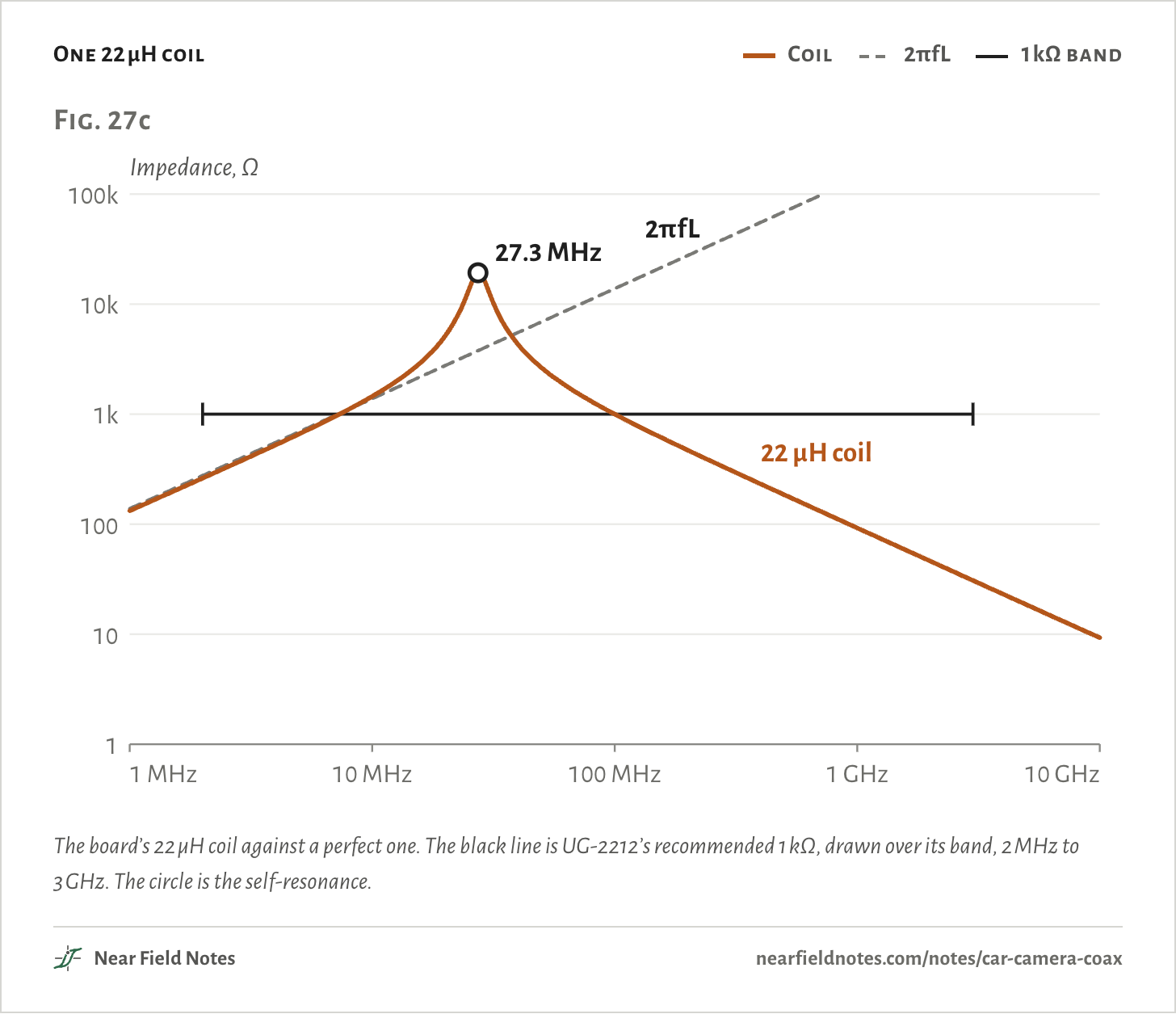
That should make a 22 µH coil a wall at 10 MHz, and Coilcraft’s model of the real part gives 1,451 Ω there. But every coil has some capacitance across its winding. At its self-resonant frequency the two cancel:

fSRF=12πLCp

=12π19.7 µH×1.72 pF=27.3 MHz

The model’s inductance sags a little as frequency rises, to the value above at resonance. Past that point the coil acts like a capacitor, and its impedance falls. By 3 GHz the 22 µH coil is down to 31 Ω.

One 22 µH coil
  • Coil
  • 2πfL
  • 1 kΩ band
Fig. 27cImpedance, Ω1101001k10k100k1 MHz100 MHz10 GHz27.3 MHz2πfL22 µH coilFig. 27cImpedance, Ω1101001k10k100k1 MHz10 MHz100 MHz1 GHz10 GHz27.3 MHz2πfL22 µH coilFig. 27cImpedance, Ω1101001k10k100k1 MHz10 MHz100 MHz1 GHz10 GHz27.3 MHz2πfL22 µH coil
The board’s 22 µH coil against a perfect one. The black line is UG-2212’s recommended 1 kΩ, drawn over its band, 2 MHz to 3 GHz. The circle is the self-resonance.
The numbers
Coilcraft’s model of the coil, fitted to its curve for the whole filter. No DC current through it.
FrequencyIdeal, 2πfL22 µH coil
1 MHz138 Ω132 Ω
2 MHz276 Ω262 Ω
10 MHz1,382 Ω1,451 Ω
30 MHz4,147 Ω13,711 Ω
100 MHz13,820 Ω999 Ω
300 MHz41,471 Ω310 Ω
1 GHz138,200 Ω92 Ω
3 GHz414,706 Ω31 Ω
10 GHz1,382,000 Ω9 Ω
518

Four coils, smallest nearest the line

Each strong where the others are weak

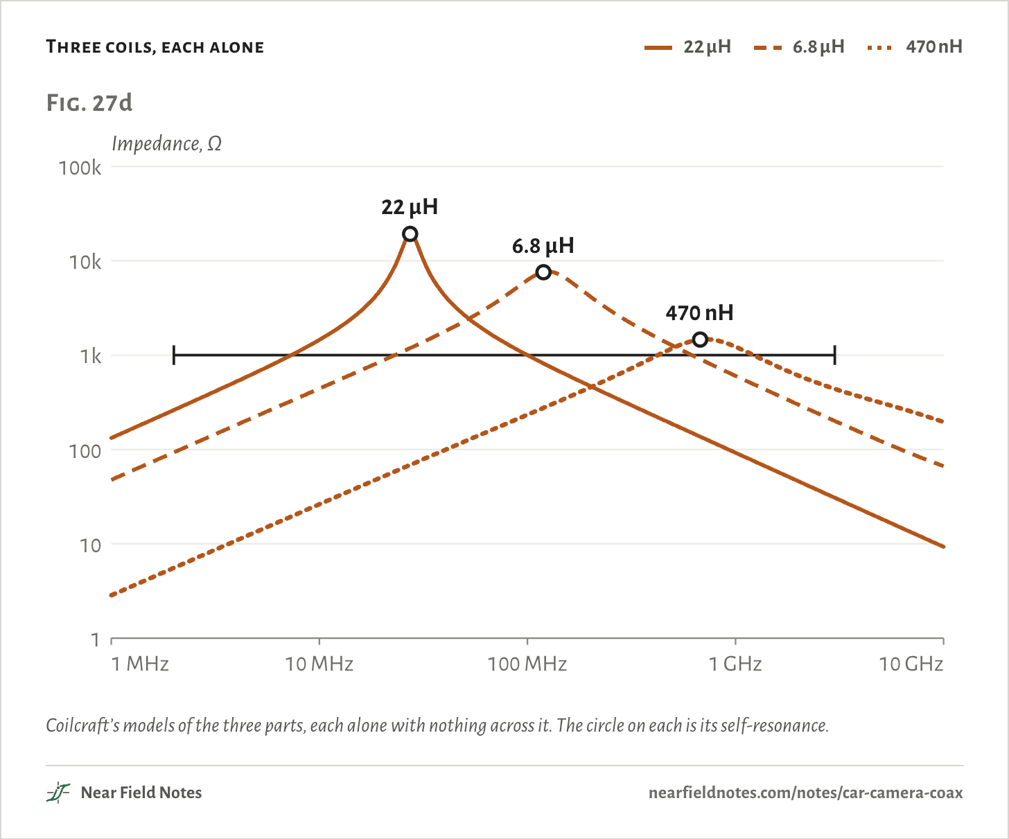
No one coil covers 2 MHz to 3 GHz, so the board stacks three kinds. Each peaks at its own self-resonance: the 22 µH coil at 27.3 MHz, the 6.8 µH at 119 MHz and the 470 nH at 676 MHz.

Below its peak each acts like a coil. Above it, each acts like a capacitor.

ADI’s data sheet asks for the smallest coil, the one with the highest self-resonance, on the signal trace. The board puts both 470 nH coils there, then the 6.8 µH, then the 22 µH at the 12 V end.

Three coils, each alone
  • 22 µH
  • 6.8 µH
  • 470 nH
Fig. 27dImpedance, Ω1101001k10k100k1 MHz100 MHz10 GHz22 µH6.8 µH470 nHFig. 27dImpedance, Ω1101001k10k100k1 MHz10 MHz100 MHz1 GHz10 GHz22 µH6.8 µH470 nHFig. 27dImpedance, Ω1101001k10k100k1 MHz10 MHz100 MHz1 GHz10 GHz22 µH6.8 µH470 nH
Coilcraft’s models of the three parts, each alone with nothing across it. The circle on each is its self-resonance.
The numbers
Coilcraft’s models of the three parts on the board, each coil alone, no resistor across it.
Frequency22 µH6.8 µH470 nH
1 MHz132 Ω48 Ω3 Ω
2 MHz262 Ω93 Ω6 Ω
10 MHz1,451 Ω442 Ω26 Ω
30 MHz13,711 Ω1,307 Ω75 Ω
100 MHz999 Ω6,234 Ω234 Ω
300 MHz310 Ω2,317 Ω687 Ω
1 GHz92 Ω603 Ω1,228 Ω
3 GHz31 Ω201 Ω439 Ω
10 GHz9 Ω67 Ω195 Ω
Self-resonance27.3 MHz119 MHz676 MHz
Share of 2 MHz to 3 GHz at 1 kΩ or more36%45%14%

In series their impedances add, as complex numbers:

ZPoC=ZL6+ZL5+(ZL4∥R)+(ZL3∥R)

=(0.5 + j5.5)+(0.5 + j5.5)+(10.7 + j92.5)+(26.7 + j259.6)=38.4 + j363.1 Ω→365 Ω

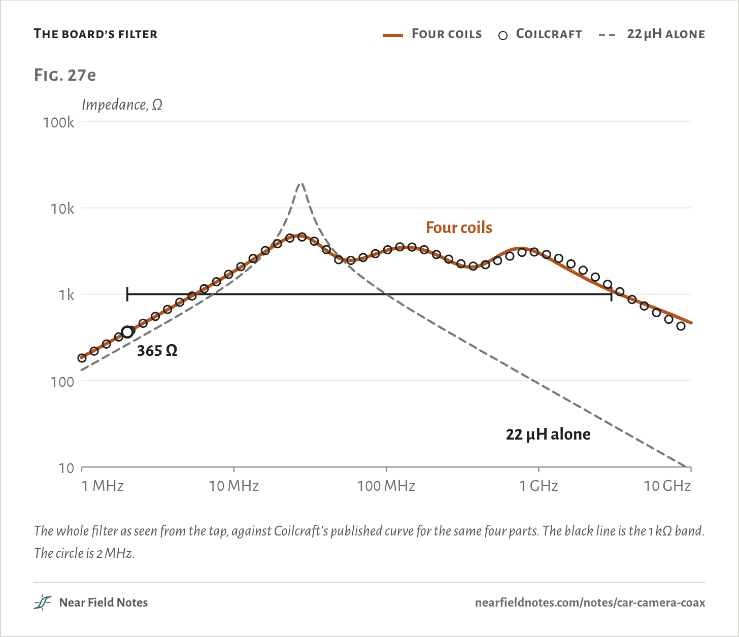
That is 2 MHz, the bottom of ADI’s band. The two 470 nH coils add almost nothing there, and the sum stops at 365 Ω. At 3 GHz the big coils have turned into small capacitors, and the two 470 nH coils supply most of the 1,098 Ω.

The 5.1 kΩ resistors across the two big coils flatten their peaks. The 6.8 µH coil does more than fill a gap. Take it out of a filter with one 470 nH coil and the two left resonate together, dipping to 251 Ω at 197 MHz.

The board’s filter
  • Four coils
  • Coilcraft
  • 22 µH alone
Fig. 27eImpedance, Ω101001k10k100k1 MHz100 MHz10 GHz365 ΩFour coils22 µH aloneFig. 27eImpedance, Ω101001k10k100k1 MHz10 MHz100 MHz1 GHz10 GHz365 ΩFour coils22 µH aloneFig. 27eImpedance, Ω101001k10k100k1 MHz10 MHz100 MHz1 GHz10 GHz365 ΩFour coils22 µH alone
The whole filter as seen from the tap, against Coilcraft’s published curve for the same four parts. The black line is the 1 kΩ band. The circle is 2 MHz.
The numbers
Coilcraft’s curve is read off its SMD-POC-006 sheet. The model is fitted to it, 8% rms.
FrequencyFour coilsCoilcraft’s curve22 µH alone
1 MHz185 Ω132 Ω
2 MHz365 Ω364 Ω262 Ω
10 MHz1,834 Ω1,854 Ω1,451 Ω
30 MHz4,556 Ω4,474 Ω13,711 Ω
100 MHz3,207 Ω3,245 Ω999 Ω
300 MHz2,184 Ω2,294 Ω310 Ω
1 GHz2,988 Ω3,059 Ω92 Ω
3 GHz1,098 Ω1,227 Ω31 Ω
10 GHz465 Ω9 Ω
520

Control data comes back on the same wire

Both ways at once

The video flows out of the camera at 6 Gb/s. The control data flows in at 187.5 Mb/s, on the same center conductor, at the same time.

ADI’s channel spec plans the control data from 2 MHz to 400 MHz and the video from 100 MHz to 3.5 GHz. It says so plainly: “The energy of the forward and reverse channel overlaps in frequency.” So a filter can’t pull them apart. At the camera’s pin, its own signal is about twice the size of the control data arriving.

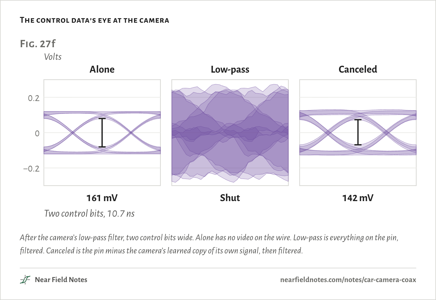
Both GMSL2 chips carry “an echo cancellation circuit” for this. Each one knows what it is sending. ADI publishes nothing on how its canceler is built. A textbook canceler learns how its own signal looks at the pin, reflections included, from the bits it sent. It subtracts that copy, and the other end’s signal is what’s left.

The control data’s eye at the camera
Fig. 27fVolts−0.200.2Alone161 mVLow-passShutCanceled142 mVTwo control bits, 10.7 nsFig. 27fVolts−0.200.2Alone161 mVLow-passShutCanceled142 mVTwo control bits, 10.7 nsFig. 27fVolts−0.200.2Alone161 mVLow-passShutCanceled142 mVTwo control bits, 10.7 ns
After the camera’s low-pass filter, two control bits wide. Alone has no video on the wire. Low-pass is everything on the pin, filtered. Canceled is the pin minus the camera’s learned copy of its own signal, then filtered.
The numbers
Over the last 1200 control bits of 2400, sampled where the control data alone opens widest.
At the camera’s receiverEye opening
Control data alone161 mV
Everything, low-passedShut, 77 mV overlap
Own signal subtracted, then low-passed142 mV
522

Three ways to share a wire

Split, cancel or take turns

Canceling is one of three ways links send control data back. The oldest splits the wire by frequency. TI’s DS90UB913A and 914A keep their control channel near 1 to 5 MHz and their video near 70 to 700 MHz, “because they occupy different spaces in the frequency domain.”

The price is a slow back channel. ADI’s GMSL1 serializer, the MAX96705, sends control data as “a series of 1μs pulses, with a maximum raw data rate of 1Mbps.” ADI’s guide asks GMSL1 power filters to be checked from 50 kHz, not 2 MHz.

The third way takes turns. ASA Motion Link’s physical layer “is based on Time Division Duplexing,” and “Downstream and Upstream traffic does not overlap on the wire.” Each 27.38 µs cycle sends video for 25.92 µs and listens for 0.86 µs, which leaves 0.60 µs for gaps.

Nothing overlaps, so there is nothing to cancel. The video has to make up the time it loses, so the line runs faster than the video:

rlinervideo=TcycleTdown

=27.38 µs25.92 µs=1.056

That is at least 5.6% faster. Each end also holds the video that waits while the link listens. For 8 Gb/s of video:

B=rvideo(Tcycle−Tdown)

=8 Gb/s×1.46 µs=11,680 bits=1.46 kB

MIPI publishes no method for A-PHY. A Valens patent, which doesn’t name A-PHY, describes coding the downlink so its low frequencies stay quiet, which “enables band separation between downlink and uplink channels.”

TI publishes nothing on how FPD-Link IV shares its wire. For the DS90UB953, an FPD-Link III part, TI gives the video 20 MHz to 2.1 GHz and the back channel 10 to 50 MHz. The two overlap from 20 to 50 MHz.

Back channels, link by link

Fig. 27g

LinkVideoBackSharing
GMSL23 or 6 Gb/s187.5 Mb/sBoth at once, each end cancels its echo
FPD-Link III, 913AAbout 70 to 700 MHzAbout 1 to 5 MHzSplit by frequency
FPD-Link III, 9534.16 Gb/s50 Mb/sBands overlap, TI names echo canceling
FPD-Link IV, 9717.55 Gb/s47.1875 Mb/sNot published
MIPI A-PHY 1.1Up to 16 Gb/s200 Mb/sNot published by MIPI
ASA Motion Link2 to 16 Gb/s50 or 100 Mb/sTakes turns
From each maker’s data sheet, training or slides. FPD-Link III’s 913A row gives TI’s bands, not rates. The 953’s overlap is worked from its two bands.

The whole 15 m link

Pin to pin

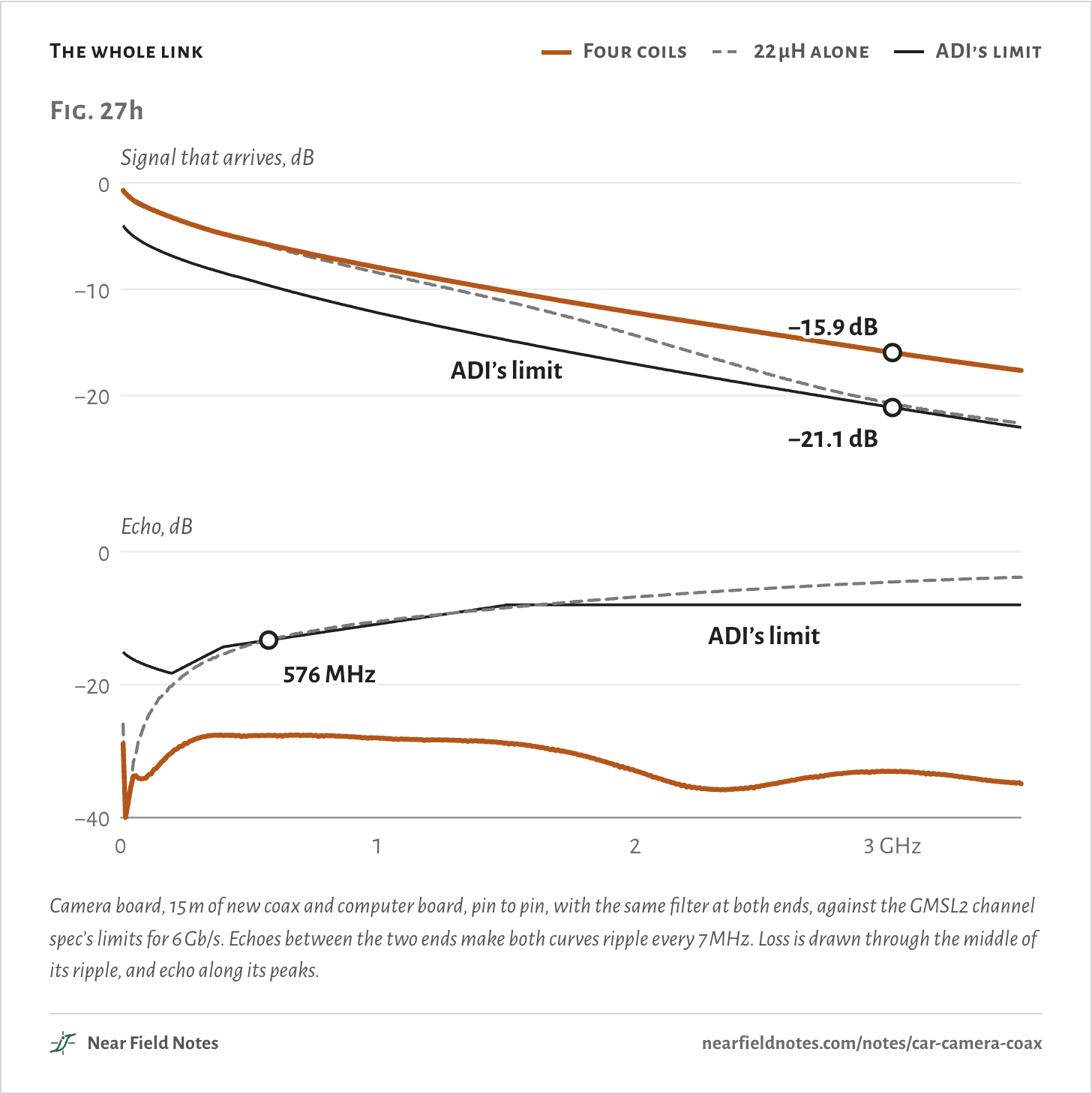
ADI’s channel spec limits the link from pin to pin: camera board, connectors, coax and computer board together. At 6 Gb/s its equation lets the signal lose up to 21.1 dB at 3 GHz.

In decibels, the losses add along the link:

Llink=Lcam+αℓ+Lcomp

=0.87 dB+0.9 dB/m×15 m+1.57 dB=15.94 dB

That is the four coils at each end and new coax, which loses 0.9 dB/m at 3 GHz by ADI’s data sheet. The coils count twice. A weak filter loads the line, which costs loss, and it reflects. ADI limits the echo because the spec uses it to judge “the high-speed transmitter energy reflected into the low-speed receiver.”

The whole link
  • Four coils
  • 22 µH alone
  • ADI’s limit
Fig. 27hSignal that arrives, dB0−10−20Echo, dB0−20−400123 GHz−15.9 dB−21.1 dBADI’s limit576 MHzADI’s limitFig. 27hSignal that arrives, dB0−10−20Echo, dB0−20−400123 GHz−15.9 dB−21.1 dBADI’s limit576 MHzADI’s limitFig. 27hSignal that arrives, dB0−10−20Echo, dB0−20−400123 GHz−15.9 dB−21.1 dBADI’s limit576 MHzADI’s limit
Camera board, 15 m of new coax and computer board, pin to pin, with the same filter at both ends, against the GMSL2 channel spec’s limits for 6 Gb/s. Echoes between the two ends make both curves ripple every 7 MHz. Loss is drawn through the middle of its ripple, and echo along its peaks.
The numbers
ADI’s loss limit is 21.1 dB at 3 GHz. Aged cable is 1.1 dB/m at 3 GHz against 0.9 new. A plus sign is room to spare.
LinkLoss at 3 GHzClosest to the loss limitEcho against its limit
Four coils, new cable15.9 dB+3.1 dB+11.5 dB
22 µH alone, new cable20.6 dB+0.2 dBOver from 576 MHz
Four coils, aged cable18.9 dB+2.0 dB+12.2 dB
22 µH alone, aged cable23.7 dB−3.0 dBOver from 735 MHz
Cable alone, new13.5 dB
Cable alone, aged16.5 dB
524

Which way back?

From the chips’ part numbers

The serializer and deserializer settle it. Their maker’s papers say how control data gets back, or say nothing.

Key to back channels

How does my camera’s link send control data back?

  1. 1aThe chips are ADI’s GMSL partsGo to 2
  2. 1bAnother familyGo to 3
  3. 2aGMSL2 or GMSL3, such as the MAX96717Both ways at once, each end cancels its echo
  4. 2bGMSL1, such as the MAX96705A slow control channel, 1 Mb/s at most
  5. 3aTI’s FPD-Link IIIGo to 4
  6. 3bAnother familyGo to 5
  7. 4aDS90UB913A or 914ASplit by frequency
  8. 4bDS90UB953Overlapping bands, and TI names echo canceling
  9. 5aASA Motion LinkTakes turns
  10. 5bTI’s FPD-Link IV or MIPI A-PHYNot published

Antmicro’s boards end at 2a. For A-PHY, a Valens patent describes separate bands, but MIPI doesn’t say A-PHY uses it.

Stack the coils yourself

Twelve filters, one 22 µH coil

Choose which coils go between the line and the 22 µH coil, and whether 5.1 kΩ resistors sit across the big ones. The curve is the filter seen from the tap.

The readings run the whole 15 m link with that filter at both ends, as in Fig. 27h.

470 nH coils
6.8 µH coil
5.1 kΩ across
The filter from the tap

Passes ADI’s loss and echo limits

  • Filter
  • 1 kΩ band
Impedance, Ω101001k10k100k1 MHz100 MHz10 GHzImpedance, Ω101001k10k100k1 MHz10 MHz100 MHz1 GHz10 GHzImpedance, Ω101001k10k100k1 MHz10 MHz100 MHz1 GHz10 GHz
At 1 kΩ or more
86%
Lowest in the band
365 Ω at 2 MHz
Link loss at 3 GHz
15.9 dB
Echo
Inside the limit
Coilcraft’s models, as in Fig. 27e. The circle is the filter’s lowest point between 2 MHz and 3 GHz. Loss and echo are judged against ADI’s limits, with new coax.
The numbers
Every filter has the 22 µH coil. The whole link uses the same filter at both ends and new cable.
470 nH coils, 6.8 µH, resistorsAt 1 kΩ or moreLowest in the bandLoss at 3 GHzEcho
Two, with 6.8 µH, no 5.1 kΩ86%366 Ω at 2 MHz15.9 dBInside
Two, with 6.8 µH, with 5.1 kΩ86%365 Ω at 2 MHz15.9 dBInside
One, with 6.8 µH, no 5.1 kΩ79%361 Ω at 2 MHz16.0 dBInside
One, with 6.8 µH, with 5.1 kΩ79%360 Ω at 2 MHz16.0 dBInside
None, with 6.8 µH, no 5.1 kΩ66%231 Ω at 3 GHz16.2 dBInside
None, with 6.8 µH, with 5.1 kΩ65%230 Ω at 3 GHz16.3 dBInside
Two, no 6.8 µH, no 5.1 kΩ64%273 Ω at 2 MHz16.0 dBInside
Two, no 6.8 µH, with 5.1 kΩ64%272 Ω at 2 MHz16.0 dBInside
One, no 6.8 µH, no 5.1 kΩ48%251 Ω at 200 MHz16.2 dBOver from 165 MHz
One, no 6.8 µH, with 5.1 kΩ48%267 Ω at 2 MHz16.2 dBOver from 192 MHz
None, no 6.8 µH, no 5.1 kΩ36%31 Ω at 3 GHz20.6 dBOver from 576 MHz
None, no 6.8 µH, with 5.1 kΩ35%31 Ω at 3 GHz20.7 dBOver from 576 MHz

Conditions

Boards
Antmicro’s GMSL Serializer rev 1.1.1 and GMSL Deserializer rev 1.0.3, Apache-2.0, from their KiCad files: the camera end and channel A of the computer end. The renders are Antmicro’s, with makers’ marks painted out.
Coils
Coilcraft’s lumped models of the PFL1609-471, 1210POC-682 and MSS6132-223. The MSS6132T-223 on the boards has no published model, so the MSS6132-223 stands in, with its capacitance, one resistor and one loss term refitted to Coilcraft’s SMD-POC-006 curve. The PFL1609 model stops at 1 GHz, so 0.07 pF across it was fitted above that. The whole filter matches the curve to 8% rms from 1 MHz to 10 GHz. No DC current, ideal resistors, and the 12 V side an AC ground.
Link
A cascade of each board’s trace, as a line with the impedance and delay from Antmicro’s own field-solver results, the 100 nF capacitor, the ESD parts’ capacitance, a stand-in for each FAKRA connector, and 15 m of coax. The coax’s loss has a part that grows with the square root of frequency and a part that grows with frequency, fitted to 0.9 dB/m at 3 GHz new and 1.1 dB/m aged. Limits from Equations 3 and 4 of the GMSL2 channel spec.
Camera’s pin
Random 6 Gb/s bits launched at 400 mV with 50 ps edges, and 187.5 Mb/s control bits launched at 250 mV with 2.3 ns edges, the data sheets’ typical figures. The camera hears its own signal, a −22 dB reflection near its connector and a −30 dB one from the far end. The canceler is a textbook LMS design spanning 48 video bits at eight phases, learning over 2,400 control bits, 12.8 µs. The receiver’s low-pass is second order at 150 MHz.
Opening
20 ns near the end of that run, once the canceler has learned.
Sums
ASA Motion Link’s line rate and buffer above are worked from Kang and Gorshe’s burst timing. The gaps’ total is what the cycle leaves after the two bursts.

Simulated only. Nothing on this page has been measured on a board yet.

Limits

  • ADI publishes nothing on its canceler. The one here is a textbook design, so Fig. 27f shows what canceling can do, not what the MAX96717 does.
  • Random bits stand in for GMSL2’s 9b10b code, which is DC-balanced and puts less of the video’s power near DC.
  • The 22 µH stand-in resonates at 27.3 MHz, against 21 MHz typical on the MSS6132T-223’s data sheet.
  • DC current lowers a coil’s inductance and moves its resonance. ADI’s rule of thumb lets saturation current cut it by no more than 10%.
  • The FAKRA connectors are stand-ins, not field-solved.
  • The video’s eye at 6 Gb/s isn’t shown. Its loss and echo are.

Files

  • sim/site.pyEvery curve and number on this page, from the three sims below
  • sim/poc.pyThe coils’ models, fitted to Coilcraft’s curve for the whole filter
  • sim/channel.pyThe whole link’s loss and echo, and ADI’s limits
  • sim/echo.pyThe camera’s pin and the echo canceler
  • post/site_boards.pyThe board renders in Fig. 27, makers’ marks painted out
  • runs/layout/Both boards’ copper, read from their KiCad files

Sources

Like this note?

Rev 1 ·
  1. Rev 1First published

Each fix gets a line here, with the reader's name if they want credit.

Did it answer your question?

Want more on this?

Report a problem

What should the next note be? Ask for one