Near Field Notes

Note 42Signal integrityRev 1Watch the video · 2:44

Retimers and redrivers

Why is there a chip beside every Thunderbolt port?

Because 20 Gb/s doesn’t survive the trip across the board. Simulated on ordinary laptop board, one USB4 lane passes the test at the port for 70 mm of trace with no chip. A 14-inch MacBook Pro’s ports sit about 130 mm from its processor. A redriver stretches the reach to 210 mm, and a retimer passed at every length tried, out to 410 mm.

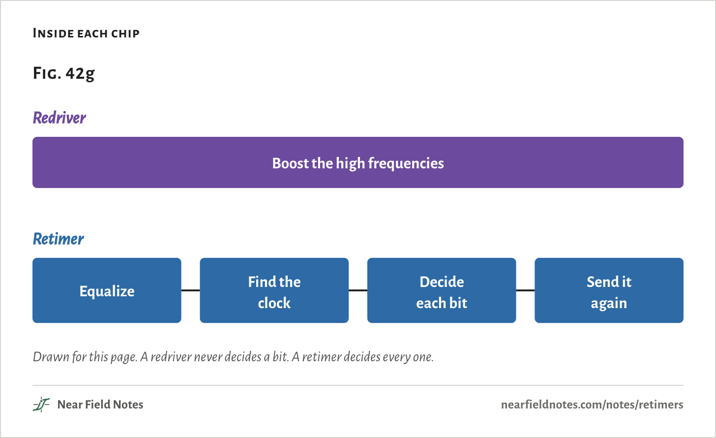
A redriver is an analog boost: it puts back the high frequencies the board took. A retimer reads every bit and sends it again from a fresh transmitter.

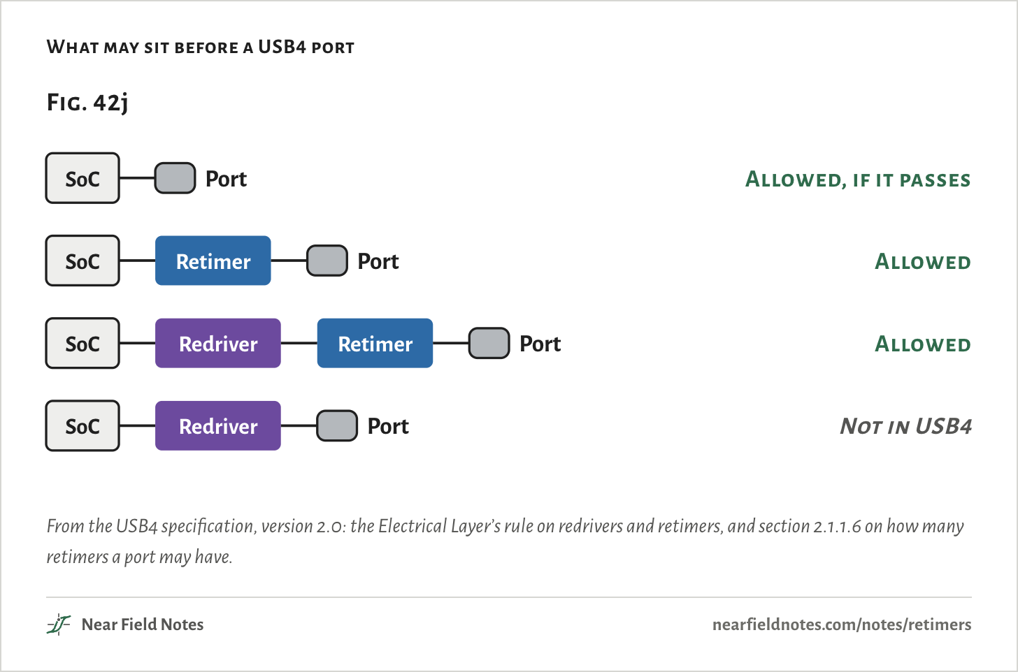
USB4 allows a redriver only with a retimer between it and the connector, so a redriver can’t be the last chip before a USB4 connector.

The eye at the port

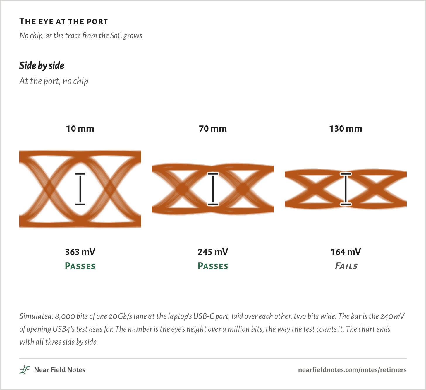
No chip, as the trace from the SoC grows

10 mm of boardAt the port, no chip363 mVPassesSoC240 mV70 mm of boardAt the port, no chip245 mVPassesSoC240 mV130 mm of boardAt the port, no chip164 mVFailsSoC240 mVSide by sideAt the port, no chip10 mm363 mVPasses70 mm245 mVPasses130 mm164 mVFails10 mm of boardAt the port, no chip363 mVPassesSoC240 mV70 mm of boardAt the port, no chip245 mVPassesSoC240 mV130 mm of boardAt the port, no chip164 mVFailsSoC240 mVSide by sideAt the port, no chip10 mm363 mVPasses70 mm245 mVPasses130 mm164 mVFails10 mm of boardAt the port, no chip363 mVPassesSoC240 mV70 mm of boardAt the port, no chip245 mVPassesSoC240 mV130 mm of boardAt the port, no chip164 mVFailsSoC240 mVSide by sideAt the port, no chip10 mm363 mVPasses70 mm245 mVPasses130 mm164 mVFails
Simulated: 8,000 bits of one 20 Gb/s lane at the laptop’s USB-C port, laid over each other, two bits wide. The bar is the 240 mV of opening USB4’s test asks for. The number is the eye’s height over a million bits, the way the test counts it. The chart ends with all three side by side.

One USB4 lane, from the SoC to the port

20 Gb/s, 50 ps a bit

A Thunderbolt 4 or USB4 port moves 40 Gb/s over two lanes each way, 20 Gb/s on each. One bit lasts 50 ps.

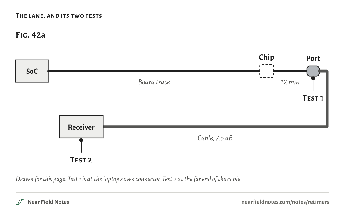
This page follows one lane from a laptop’s SoC along a board trace to its USB-C port, then down a 0.8 m cable to a receiver. Every part on the way loses more at high frequencies than at low ones. The trace loses the most, and more the longer it gets: 1.4 dB per inch at 10 GHz on ordinary laptop board.

When there is a chip, it sits 12 mm of trace before the connector. The trace is swept from 10 to 410 mm, three times: with no chip, with a redriver and with a retimer.

The lane, and its two tests
Fig. 42aSoCChipBoard trace12 mmPortReceiverCable, 7.5 dBTest 1Test 2Fig. 42aSoCChipBoard trace12 mmPortReceiverCable, 7.5 dBTest 1Test 2Fig. 42aSoCChipBoard trace12 mmPortReceiverCable, 7.5 dBTest 1Test 2
Drawn for this page. Test 1 is at the laptop’s own connector, Test 2 at the far end of the cable.
The numbers
PartLoss at 10 GHz
SoC package and coupling capacitors1.5 dBassumed
Board trace1.4 dB per inch1.4 on ordinary laptop board, 2.0 on plain FR-4
Two vias and the ESD part1.1 dB0.8 and 0.3
USB-C connector1.0 dB
Cable, 0.8 m7.5 dBthe limit for a passive USB4 Gen 3 cable
The chip's package1.0 dBretimer only

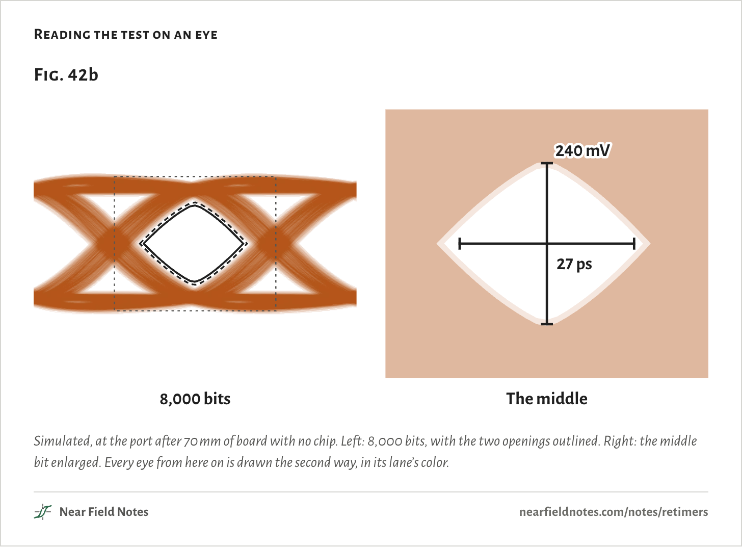
USB4 tests a laptop’s port twice. At its own connector, with no equalizer, the eye must open 240 mV, 120 each side of zero, over a million bits, and stay 27 ps wide at one error in 10¹² bits. At the far end of a cable with 7.5 dB of loss, after the spec’s reference equalizer, it must open 98 mV and stay 20 ps wide.

An eye diagram lays the bits over each other. The test counts far more bits than a picture of a few thousand can show, so the opening is drawn here as two lenses: white where no bit crosses in 10¹² bits, pale where one may cross by 10⁶.

The cross in the middle is the test. Its upright bar has to fit inside the pale lens, and its crossbar inside the white one.

Reading the test on an eye
Fig. 42b8,000 bits240 mV27 psThe middleFig. 42b8,000 bits240 mV27 psThe middleFig. 42b8,000 bits240 mV27 psThe middle
Simulated, at the port after 70 mm of board with no chip. Left: 8,000 bits, with the two openings outlined. Right: the middle bit enlarged. Every eye from here on is drawn the second way, in its lane’s color.

With no chip, the eye closes by 75 mm

245 mV at 70 mm

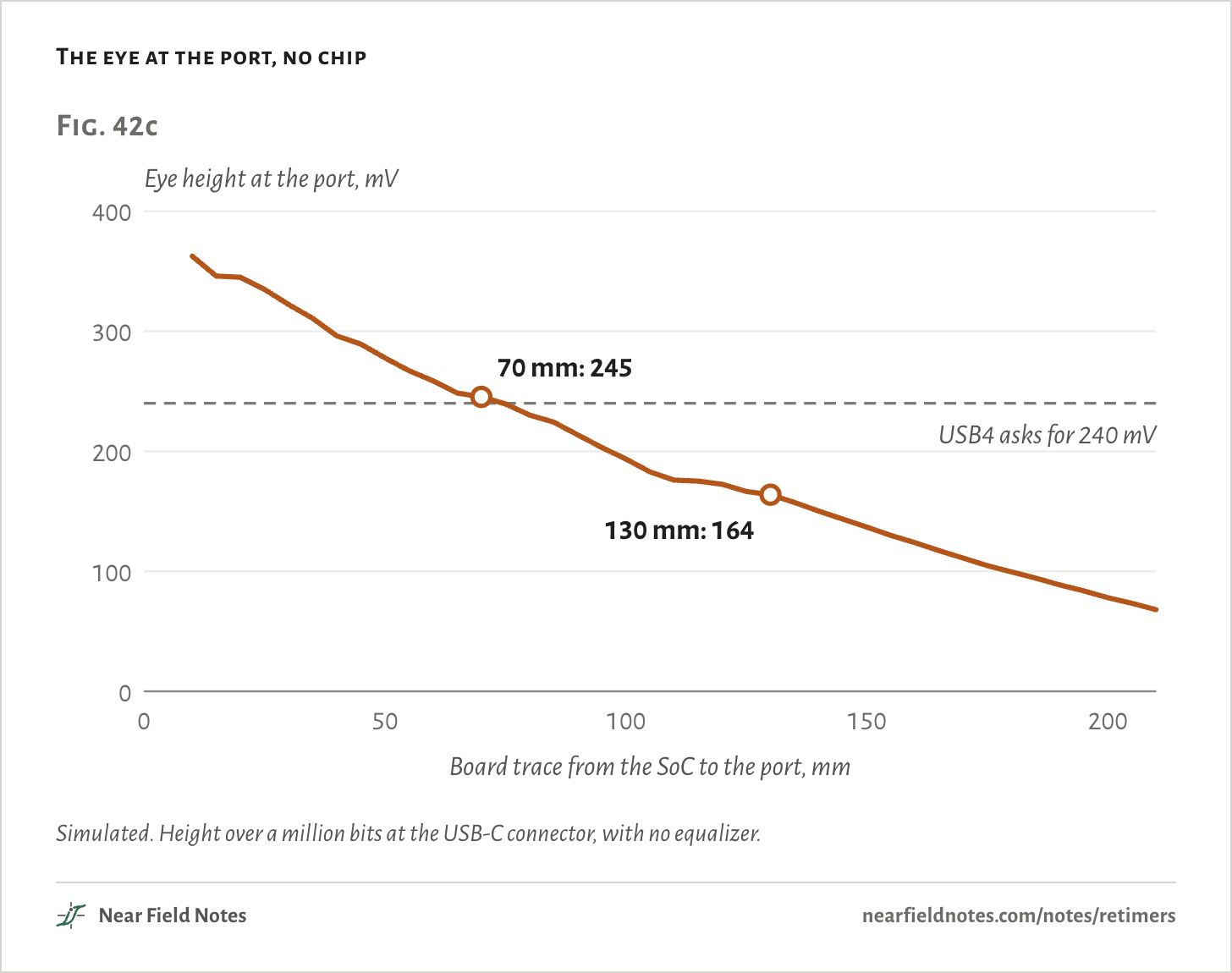
With nothing between the SoC and the port, the eye at the port is 363 mV after 10 mm of trace. It shrinks as the trace grows, and clears 240 mV for the last time at 70 mm, with 245 mV. At 75 mm it is 239.6 mV.

70 mm is a loss of 7.5 dB at 10 GHz from the SoC to the connector. That is the figure USB4 recommends for a laptop, 7.5 dB, in a section marked informative. The model wasn’t tuned to land there.

At the far end the same lane lasts a little longer, to 105 mm, so the port’s own test fails first. At 130 mm the eye at the port is 164 mV, and the far end fails too.

The eye at the port, no chip
Fig. 42cEye height at the port, mV0100200300400050100150200USB4 asks for 240 mV70 mm: 245130 mm: 164Board trace from the SoC to the port, mmFig. 42cEye height at the port, mV0100200300400050100150200USB4 asks for 240 mV70 mm: 245130 mm: 164Board trace from the SoC to the port, mmFig. 42cEye height at the port, mV0100200300400050100150200USB4 asks for 240 mV70 mm: 245130 mm: 164Board trace from the SoC to the port, mm
Simulated. Height over a million bits at the USB-C connector, with no equalizer.
The numbers

Height over a million bits, width at one error in 10¹². The port test asks for 240 mV and 27 ps.

TraceHeightWidthLoss to the port at 10 GHzPort test
10 mm362.6 mV34.6 ps4.2 dBPasses
30 mm322.4 mV33.7 ps5.2 dBPasses
50 mm277.8 mV32.3 ps6.4 dBPasses
60 mm258.7 mV32.1 ps6.9 dBPasses
65 mm248.5 mV31.9 ps7.2 dBPasses
70 mm245.3 mV30.8 ps7.5 dBPasses
75 mm239.6 mV30.7 ps7.7 dBFails
80 mm230.1 mV30.5 ps8.0 dBFails
100 mm193.6 mV29.9 ps9.1 dBFails
130 mm163.9 mV28.5 ps10.8 dBFails
160 mm123.9 mV27.4 ps12.4 dBFails
210 mm68.0 mV24.0 ps15.2 dBFails

A redriver puts back the high frequencies

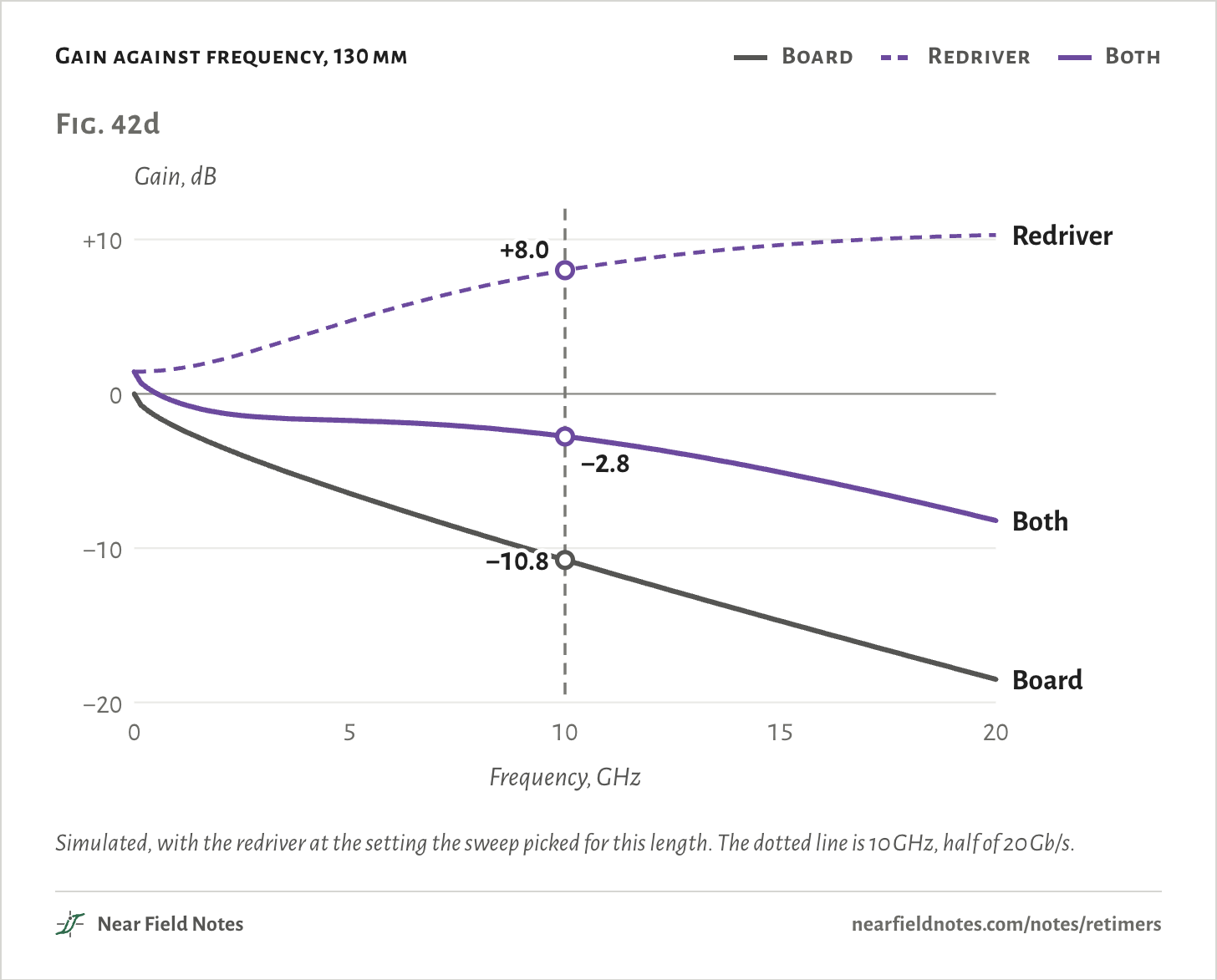
8 dB at 10 GHz

A redriver is an analog chip whose gain rises with frequency. It boosts the highs the board lost more than the lows, so each pulse comes out closer to the shape it left with.

At 130 mm the board from the SoC to the port loses 10.8 dB at 10 GHz, half the bit rate. The best setting there is 8 dB of boost, and together they lose 2.8 dB. The far receiver’s own equalizer handles the rest.

With it, the 130 mm lane passes both tests: 365 mV at the port, and 156 mV and 25.1 ps at the far end.

Gain against frequency, 130 mm
  • Board
  • Redriver
  • Both
Fig. 42dGain, dB−20−100+1005101520BoardRedriverBoth−10.8+8.0−2.8Frequency, GHzFig. 42dGain, dB−20−100+1005101520BoardRedriverBoth−10.8+8.0−2.8Frequency, GHzFig. 42dGain, dB−20−100+1005101520BoardRedriverBoth−10.8+8.0−2.8Frequency, GHz
Simulated, with the redriver at the setting the sweep picked for this length. The dotted line is 10 GHz, half of 20 Gb/s.
The numbers

The 130 mm lane, with the redriver at the 8 dB setting the sweep picked there.

FrequencyBoard, SoC to portRedriverBoth
0 GHz0.0 dB1.4 dB1.4 dB
10 GHz−10.8 dB8.0 dB−2.8 dB
20 GHz−18.5 dB10.3 dB−8.2 dB

The redriver runs out at 210 mm

30.3 ps to 20.2 ps

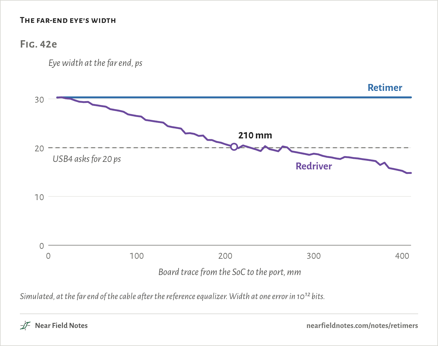
Each extra length needs more boost: 14 dB by 210 mm. Each time, the far-end eye comes out a little narrower, from 30.3 ps at 10 mm to 20.2 ps at 210 mm. At 215 mm it is 19.9 ps, under the 20 ps the far-end test asks for.

Past 210 mm the best setting passes at a few lengths, 220, 225, 245 mm, and fails at the rest. Its reach here is the last length before the first failure.

The far-end eye’s width
Fig. 42eEye width at the far end, ps01020300100200300400USB4 asks for 20 psRetimerRedriver210 mmBoard trace from the SoC to the port, mmFig. 42eEye width at the far end, ps01020300100200300400USB4 asks for 20 psRetimerRedriver210 mmBoard trace from the SoC to the port, mmFig. 42eEye width at the far end, ps01020300100200300400USB4 asks for 20 psRetimerRedriver210 mmBoard trace from the SoC to the port, mm
Simulated, at the far end of the cable after the reference equalizer. Width at one error in 10¹² bits.
The numbers

At the far end, after the reference equalizer. Width at one error in 10¹², height over a million bits. Past 210 mm the redriver's best setting passes at a few lengths and fails at the rest; its reach is the last length before the first failure.

TraceRedriver: widthheightsettingRetimer: widthRedriver, both tests
10 mm30.25 ps223 mV3 dB30.31 psPasses
50 mm28.82 ps206 mV5 dB30.32 psPasses
100 mm26.50 ps173 mV7 dB30.32 psPasses
130 mm25.14 ps156 mV8 dB30.32 psPasses
150 mm23.91 ps147 mV9 dB30.32 psPasses
200 mm20.71 ps187 mV14 dB30.32 psPasses
205 mm20.44 ps180 mV14 dB30.32 psPasses
210 mm20.18 ps175 mV14 dB30.32 psPasses
215 mm19.90 ps168 mV14 dB30.32 psFails
220 mm20.46 ps194 mV15 dB30.32 psPasses
225 mm20.18 ps185 mV15 dB30.32 psPasses
230 mm19.91 ps178 mV15 dB30.32 psFails
245 mm20.31 ps188 mV16 dB30.32 psPasses
260 mm19.27 ps166 mV16 dB30.32 psFails
300 mm18.77 ps161 mV18 dB30.32 psFails
350 mm17.79 ps133 mV19 dB30.32 psFails
410 mm14.82 ps90 mV19 dB30.32 psFails

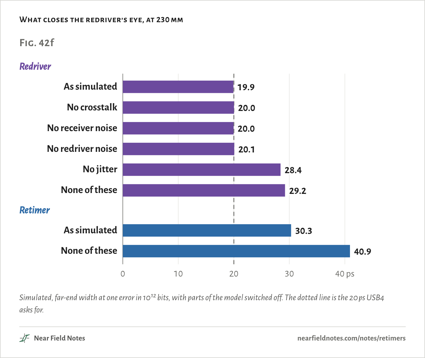
What narrows it? The model can switch parts off one at a time. At 230 mm, take away the crosstalk, the receiver’s noise or the redriver’s own noise, and the width moves by 0.2 ps at most. Noise isn’t what stops it.

Take away the jitter and the eye opens from 19.9 ps to 28.4 ps. But jitter costs the retimer just as much: 30.3 ps with it, 40.1 ps without.

Take all of them away and the redriver’s eye is 29.2 ps wide, against the retimer’s 40.9 ps. What’s left is smear: each pulse spread into its neighbors, more than the boost and the far receiver’s equalizer can take back. The smear eats the room the jitter needs.

What closes the redriver’s eye, at 230 mm
Fig. 42fRedriverRetimer010203040 psAs simulated19.9No crosstalk20.0No receiver noise20.0No redriver noise20.1No jitter28.4None of these29.2As simulated30.3None of these40.9Fig. 42fRedriverRetimer010203040 psAs simulated19.9No crosstalk20.0No receiver noise20.0No redriver noise20.1No jitter28.4None of these29.2As simulated30.3None of these40.9Fig. 42fRedriverRetimer010203040 psAs simulated19.9No crosstalk20.0No receiver noise20.0No redriver noise20.1No jitter28.4None of these29.2As simulated30.3None of these40.9
Simulated, far-end width at one error in 10¹² bits, with parts of the model switched off. The dotted line is the 20 ps USB4 asks for.
The numbers

At the far end, after the reference equalizer. Width at one error in 10¹², height over a million bits. The redriver keeps the 15 dB setting the sweep picked at this length.

At 230 mmRedriver: widthheightRetimer: widthheight
As simulated19.91 ps177.8 mV30.32 ps175.4 mV
No crosstalk20.03 ps178.2 mV30.50 ps176.0 mV
No receiver noise19.95 ps177.9 mV30.41 ps175.7 mV
No redriver noise20.07 ps178.4 mV30.32 ps175.4 mV
No jitter28.42 ps223.4 mV40.08 ps206.3 mV
None of these29.23 ps226.3 mV40.92 ps209.6 mV

A retimer starts the signal over

175 mV and 30.3 ps at every length

A retimer is a receiver and a transmitter in one package. It equalizes what arrives, finds the clock in it, decides whether each bit is a 1 or a 0, and sends the bits again at full swing.

So the far end only ever sees the 12 mm of trace and the connector after the retimer. The board before it is the retimer’s problem: its own receiver has to read every bit right. USB4 trains each hop on its own, the SoC to the retimer and the retimer to the far end.

Inside each chip
Fig. 42gRedriverBoost the high frequenciesRetimerEqualizeFind theclockDecideeach bitSend itagainFig. 42gRedriverBoost the high frequenciesRetimerEqualizeFind theclockDecideeach bitSend itagainFig. 42gRedriverBoost the high frequenciesRetimerEqualizeFind theclockDecideeach bitSend itagain
Drawn for this page. A redriver never decides a bit. A retimer decides every one.

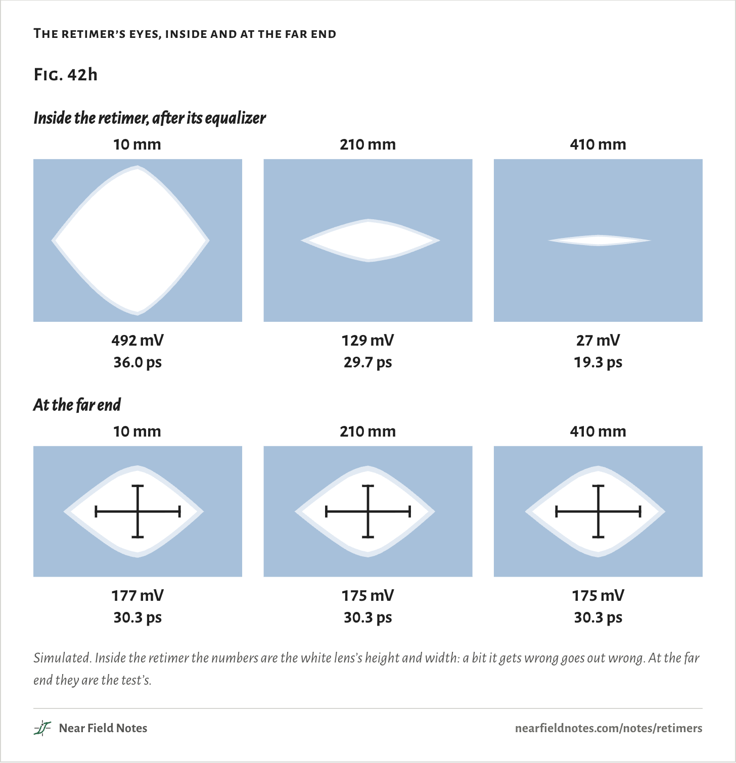
The far-end eye comes out the same at every length: 175 mV tall and 30.3 ps wide. At the port it is 388 mV.

What changes is the eye inside the retimer, after its own equalizer. At 410 mm, the end of the sweep, it is down to 26.5 mV and 19.3 ps at one error in 10¹², and still open. Kandou says its KB8001 retimer can sit about 40 cm from the SoC on low-cost board.

A bit-by-bit run of 8,000 bits found no wrong bits at the retimer at any length. A real retimer that gets a bit wrong sends the wrong bit on, cleanly.

The retimer’s eyes, inside and at the far end
Fig. 42hInside the retimer, after its equalizer10 mm492 mV36.0 ps210 mm129 mV29.7 ps410 mm27 mV19.3 psAt the far end10 mm210 mm410 mm177 mV30.3 ps175 mV30.3 ps175 mV30.3 psFig. 42hInside the retimer, after its equalizer10 mm492 mV36.0 ps210 mm129 mV29.7 ps410 mm27 mV19.3 psAt the far end10 mm210 mm410 mm177 mV30.3 ps175 mV30.3 ps175 mV30.3 psFig. 42hInside the retimer, after its equalizer10 mm492 mV36.0 ps210 mm129 mV29.7 ps410 mm27 mV19.3 psAt the far end10 mm210 mm410 mm177 mV30.3 ps175 mV30.3 ps175 mV30.3 ps
Simulated. Inside the retimer the numbers are the white lens’s height and width: a bit it gets wrong goes out wrong. At the far end they are the test’s.
The numbers

Inside the retimer, height and width at one error in 10¹². At the far end, height over a million bits and width at 10¹².

TraceInside: heightwidthequalizerFar end: heightwidth
10 mm491.5 mV36.0 ps0 dB176.8 mV30.3 ps
50 mm381.6 mV35.4 ps1 dB175.3 mV30.3 ps
100 mm276.1 mV34.0 ps2 dB175.3 mV30.3 ps
130 mm223.2 mV33.0 ps3 dB175.3 mV30.3 ps
200 mm136.2 mV30.2 ps5 dB175.3 mV30.3 ps
250 mm100.3 mV27.3 ps6 dB175.3 mV30.3 ps
300 mm67.5 mV25.3 ps7 dB175.3 mV30.3 ps
350 mm47.2 mV23.0 ps9 dB175.3 mV30.3 ps
400 mm29.6 mV20.9 ps9 dB175.3 mV30.3 ps
410 mm26.5 mV19.3 ps11 dB175.3 mV30.3 ps

How far each one reaches

70, 210 and 410+ mm

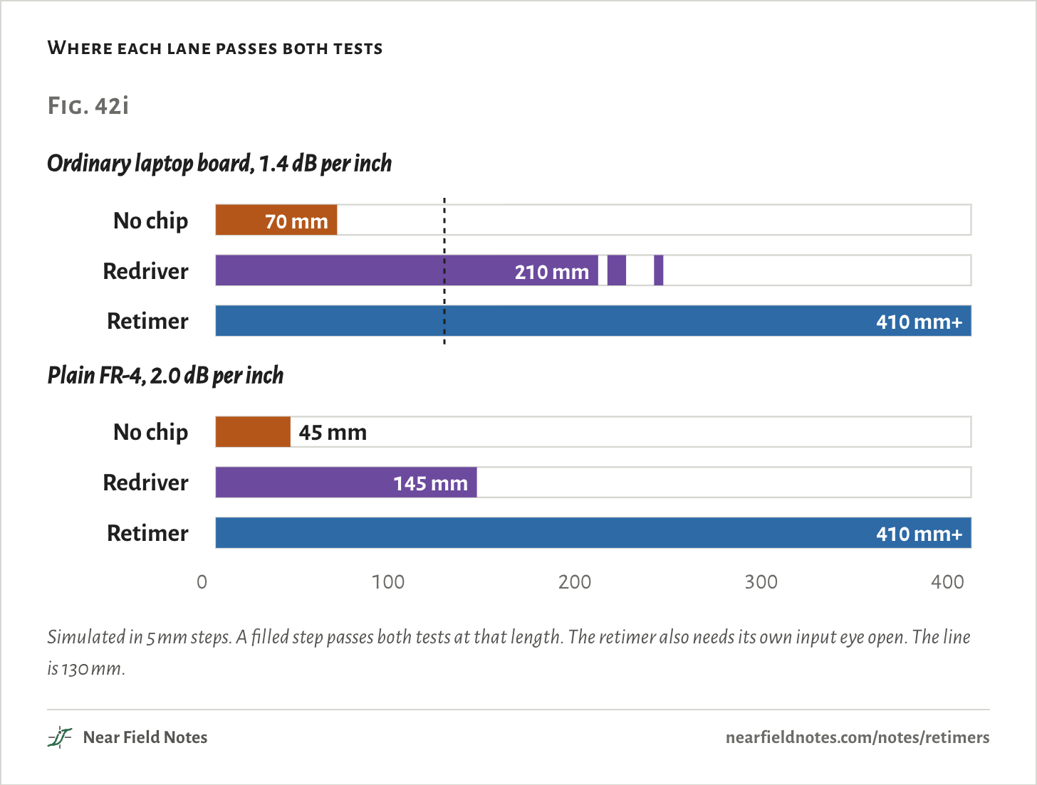
Side by side, the three lanes pass both tests to 70 mm, 210 mm and 410 mm, the end of the sweep.

A 14-inch MacBook Pro’s three ports sit about 11 to 14 cm from the middle of its M1 Pro, in a straight line, scaled from iFixit’s photo. A routed trace is longer. At 130 mm the lane with no chip fails both tests, and the redriver and the retimer both pass.

The board matters as much as the chip. On plain FR-4, at 2.0 dB per inch, the reaches drop to 45 mm and 145 mm. The retimer still passes at 410 mm, but its own eye is 19.6 ps wide at 300 mm and only 1.8 ps at 410.

Where each lane passes both tests
Fig. 42iOrdinary laptop board, 1.4 dB per inchNo chipRedriverRetimerPlain FR-4, 2.0 dB per inchNo chipRedriverRetimer70 mm210 mm410 mm+45 mm145 mm410 mm+0100200300400Fig. 42iOrdinary laptop board, 1.4 dB per inchNo chipRedriverRetimerPlain FR-4, 2.0 dB per inchNo chipRedriverRetimer70 mm210 mm410 mm+45 mm145 mm410 mm+0100200300400Fig. 42iOrdinary laptop board, 1.4 dB per inchNo chipRedriverRetimerPlain FR-4, 2.0 dB per inchNo chipRedriverRetimer70 mm210 mm410 mm+45 mm145 mm410 mm+0100200300400
Simulated in 5 mm steps. A filled step passes both tests at that length. The retimer also needs its own input eye open. The line is 130 mm.

Move the port yourself

10 to 410 mm

Slide the port away from the SoC. Each column is one lane and each row one of USB4’s tests. A lane passes a test when the cross fits its eye.

130 mm
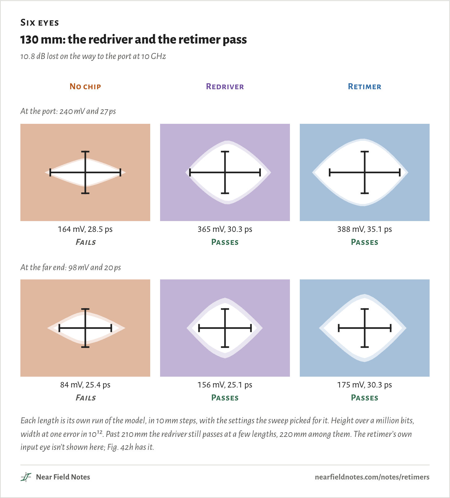
Six eyes

130 mm: the redriver and the retimer pass

10.8 dB lost on the way to the port at 10 GHz

No chip

Redriver

Retimer

At the port: 240 mV and 27 ps

164 mV, 28.5 psFails

365 mV, 30.3 psPasses

388 mV, 35.1 psPasses

At the far end: 98 mV and 20 ps

84 mV, 25.4 psFails

156 mV, 25.1 psPasses

175 mV, 30.3 psPasses

Each length is its own run of the model, in 10 mm steps, with the settings the sweep picked for it. Height over a million bits, width at one error in 10¹². Past 210 mm the redriver still passes at a few lengths, 220 mm among them. The retimer’s own input eye isn’t shown here; Fig. 42h has it.

USB4 rules out a redriver at the port

Up to two retimers

USB4 settles which chip goes nearest the port. A redriver may sit inside the laptop, but only with a retimer after it: “If a Router Assembly contains Linear Re-drivers, a Re-timer shall be placed between the Linear Re-driver and the USB Type-C connector.” A port may have up to two retimers.

No chip at all is allowed too. USB4 judges the port at its connector, and its 7.5 dB is a recommendation. A port close enough to its SoC needs nothing.

A redriver working alone belongs to slower links. USB 3.2’s appendix on repeaters covers redrivers on the board with no retimer, for 10 Gb/s and a host allowance of 8.5 dB at 5 GHz. The iPhone 15 Pro’s port runs at 10 Gb/s, and iFixit lists no such chip beside it. Framework kept Thunderbolt off its 12-inch laptop; its CEO wrote that “Thunderbolt requires much more expensive retimers.”

What may sit before a USB4 port
Fig. 42jSoCPortAllowed, if it passesSoCRetimerPortAllowedSoCRedriverRetimerPortAllowedSoCRedriverPortNot in USB4Fig. 42jSoCPortAllowed, if it passesSoCRetimerPortAllowedSoCRedriverRetimerPortAllowedSoCRedriverPortNot in USB4Fig. 42jSoCPortAllowed, if it passesSoCRetimerPortAllowedSoCRedriverRetimerPortAllowedSoCRedriverPortNot in USB4
From the USB4 specification, version 2.0: the Electrical Layer’s rule on redrivers and retimers, and section 2.1.1.6 on how many retimers a port may have.

Where the chips are

Laptops, a Mac mini, a phone, a cable
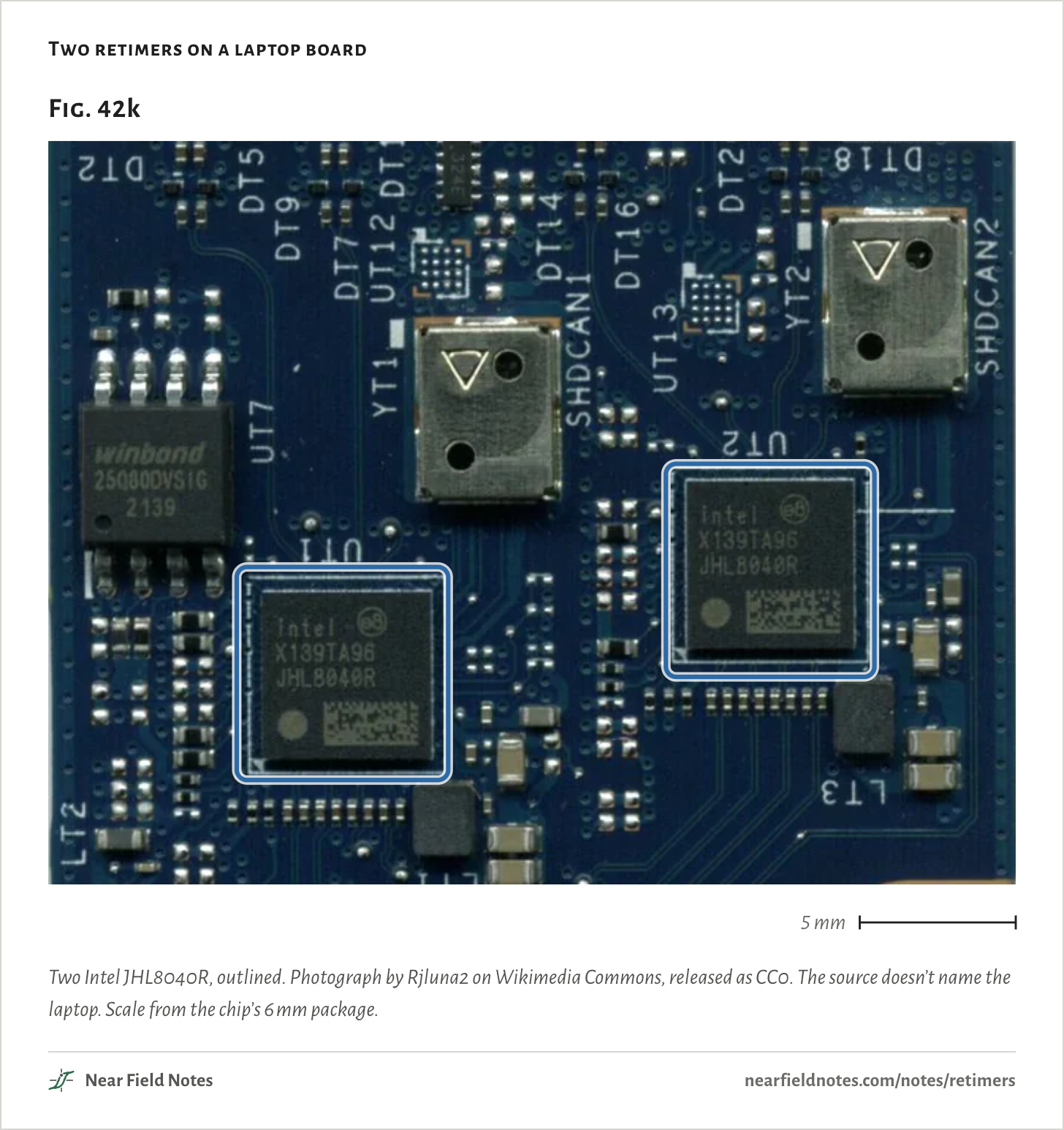
Two retimers on a laptop board
Fig. 42k5 mmFig. 42k5 mmFig. 42k5 mm
Two Intel JHL8040R, outlined. Photograph by Rjluna2 on Wikimedia Commons, released as CC0. The source doesn’t name the laptop. Scale from the chip’s 6 mm package.
420

An M1 Mac mini’s logic board (2020)

The M1 at right, and at left its two Intel JHL8040R retimers, outlined, each with a small crystal just above it. The retimers are 6 mm square. Photo: Sonic8400, via Wikimedia Commons, cropped, with outlines added. License: CC BY-SA 4.0, outlines included. Unlike this page’s figures, it isn’t under CC BY 4.0.
Fast ports and the chips beside them

Fig. 42l

DeviceFast portsBeside themSource
MacBook Air and 13-inch MacBook Pro, M1 (2020)2 ThunderboltIntel JHL8040R retimer, twoiFixit
14-inch MacBook Pro, M1 Pro (2021)3 Thunderbolt 4Intel JHL8040R retimer, one inboard of each portiFixit
MacBook Air, M2 (2022)2 ThunderboltAn Apple-marked chip where the Intel retimers were. iFixit: “likely” a redriver; Tom’s Hardware: a retimeriFixit, Tom’s Hardware
Surface Laptop 7, 13.8-inch (2024)2 USB4Parade PS8830 retimer, one inboard of each portiFixit
Framework Laptop 13, AMD Ryzen 7040 (2023)2 USB4, 2 USB 3.2Kandou retimers on the two USB4 slots, an Analogix retimer on one USB 3.2 slotFramework
Framework Laptop 12 (2025)4 USB 3.2No Thunderbolt: it “requires much more expensive retimers”Framework’s CEO
iPhone 15 Pro (2023)1 USB 3, 10 Gb/sNone listediFixit
Apple Thunderbolt 4 Pro cableIn the plugs1.8 m: an Intel JHL7040 retimer. 1 m: none, a passive cableChargerLAB
From teardowns and the makers’ own words, each named in Sources. A chip missing from a teardown’s list isn’t proof it isn’t there. Nobody has published what is inside the M2 MacBook Air’s Apple chip.

What goes beside a fast port?

Two questions

It comes down to the speed of the link and the loss between the SoC and the connector.

Key to a fast USB-C port

What sits beside it?

  1. 1a10 Gb/s or less, USB 3.2Nothing if the port passes; otherwise a redriver can work alone
  2. 1b20 Gb/s a lane, USB4 or ThunderboltGo to 2
  3. 2aThe port passes with nothing in the wayNo chip
  4. 2bIt doesn’tA retimer, last before the connector; a redriver only before it

USB4 recommends 7.5 dB or less at 10 GHz from the SoC to the connector, about 70 mm of ordinary laptop board in Fig. 42c. The test at the connector decides.

Conditions

Simulated
Every eye, height, width and reach on this page comes from a statistical model of one lane, in the style of IEEE 802.3’s Annex 93A. None was measured on a bench.
Lane
One USB4 Gen 3 lane, 20 Gb/s, 50 ps a bit. Transmitter 800 mV peak to peak with a 20 ps edge, and the best of USB4’s 16 presets at each length.
Board
1.4 dB per inch at 10 GHz, scaled from Intel’s measurements of a reference board at 8 GHz, 1.06 to 1.38 dB per inch. It is the weakest number here. Plain FR-4: 2.0 dB per inch, from TI’s rule of 0.2 dB per inch per GHz.
Fixed parts
At 10 GHz: SoC package and coupling capacitors 1.5 dB (assumed), two vias 0.8, the ESD part 0.3, the connector 1.0.
Cable
0.8 m, 7.5 dB at 10 GHz, USB4’s figure for a Gen 3 passive cable.
Redriver
Linear, 12 mm of trace before the connector: 0 to 19 dB of boost at 10 GHz in 1 dB steps, the best setting at each length, 3 mV rms of its own noise, linear to 1.2 V peak to peak.
Retimer
12 mm before the connector, behind 1.0 dB of its own package. Its receiver has the reference equalizer’s shape with 0 to 24 dB, and one feedback tap of up to 50 mV. Its transmitter is like the SoC’s.
Receiver
At the far end, USB4’s reference equalizer: 0 to 9 dB and one decision-feedback tap of up to 50 mV. Crosstalk at −44 dB at 10 GHz, receiver noise, 0.01 UI rms of random jitter and 0.085 UI of bounded jitter.
Tests
USB4 Table 3-7 at the port, no equalizer: 240 mV over 10⁶ bits and total jitter 0.46 UI at 10⁻¹², so 27 ps of eye. Table 3-8 at the far end: 98 mV over 10⁶ bits and total jitter 0.60 UI, so 20 ps.
Sweep
10 to 410 mm in 5 mm steps. A lane’s reach is the last length before its first failure. The retimer also needs its own input eye open.
Check
A bit-by-bit run of 8,000 bits at every length, with the same settings, draws the eye pictures. The retimer decided every bit right. The pictures open a little wider than the numbers, which count rarer bits.

A model of one lane. Nothing on this page has been measured on a bench.

Limits

  • The board’s loss is scaled, not measured. A lower-loss laminate or package moves every reach, and plain FR-4 cuts them to 45 mm and 145 mm.
  • Loss only: no reflections from via stubs, the connector or the package, and crosstalk as one fixed level.
  • The redriver is an ideal linear one, with one zero and two poles. Real redrivers’ curves differ.
  • A model in the style of Annex 93A, not USB4’s compliance software.
  • Past 210 mm the redriver passes at 220, 225, 245 mm and fails at the rest. The reach counts the first failure, at 215 mm.
  • On FR-4 at 410 mm the retimer passes, but its input eye is 1.8 ps wide. That pass rests on the eye being open at all.
  • The 130 mm is a straight-line distance scaled from a photo, good to about 30%. A routed trace is longer.
  • Teardown lists aren’t complete. A chip missing from one isn’t proof it isn’t there.
  • Power, delay and cost aren’t modeled.

Files

  • sim/link.pyThe lane: its parts, the statistical eye, both tests, the sweep, the parts switched off one at a time, the bit-by-bit eyes and the numbers for this page

Sources

Like this note?

Rev 1 ·
  1. Rev 1First published

Each fix gets a line here, with the reader's name if they want credit.

Did it answer your question?

Want more on this?

Report a problem

What should the next note be? Ask for one