Current sense errors
How far off can a motor driver’s current reading be with every part in spec?
By the datasheets, moteus-c1’s current sensor can read 2.0 A with the motor stopped, and a true 10 A can read anywhere from 8 to 12 A. Zeroing at startup, which moteus’s firmware does every time the driver turns on, narrows that to 9.5 to 10.5 A. A one-point gain calibration takes it to 9.7 to 10.3 A. What’s left is the amp’s drift as the board warms.
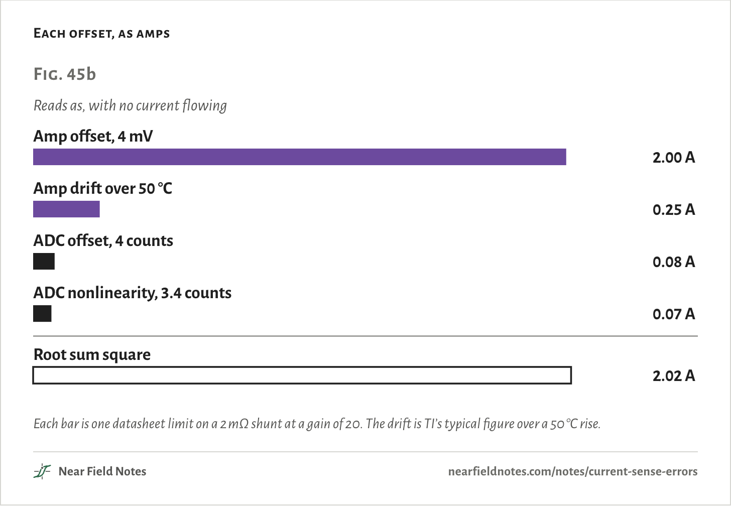
The amp is allowed 4 mV of offset. Across a 2 mΩ shunt, that reads as 2 A.
Below is every error in the chain, two ways to add them up, and what each calibration takes out.
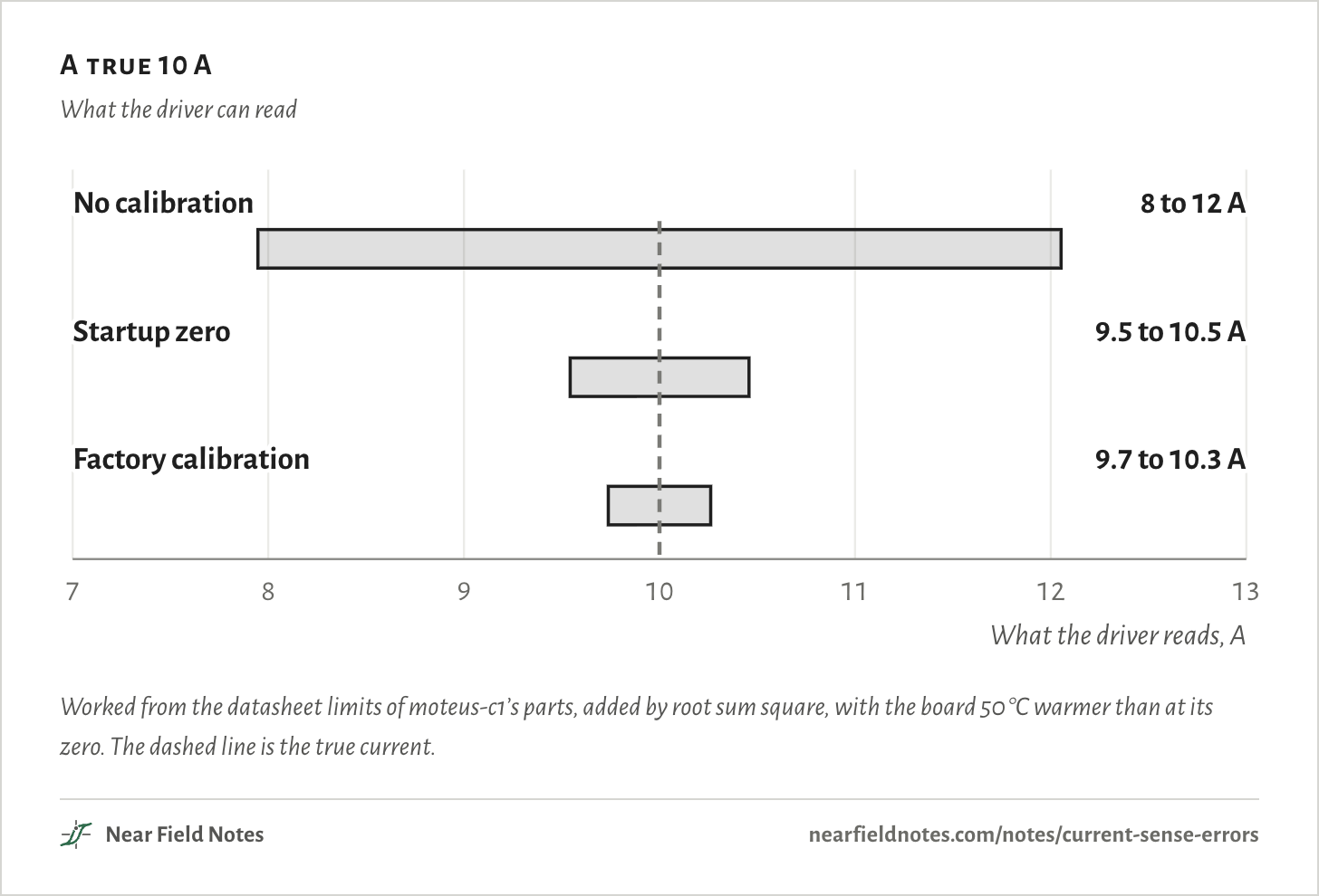
The numbers
| State | A true 10 A reads as | Error either way |
|---|---|---|
| No calibration | 8 to 12 A | 2.05 A |
| Startup zero | 9.5 to 10.5 A | 0.46 A |
| Factory calibration | 9.7 to 10.3 A | 0.26 A |
One phase, four parts
moteus-c1, phase Amoteus-c1 is a 38 mm square motor controller from mjbots. Its schematics and firmware are open, so its current sensor can be followed part by part.
It senses low side. Each phase’s current returns to ground through a 2 mΩ shunt under the bottom FET. An amp inside the DRV8323 gate driver multiplies the shunt’s few millivolts by 20.
The amp’s output passes a 22 Ω resistor and a 1 nF capacitor on its way to the microcontroller’s 12-bit ADC. One 3.3 V rail is the reference for both the amp and the ADC.
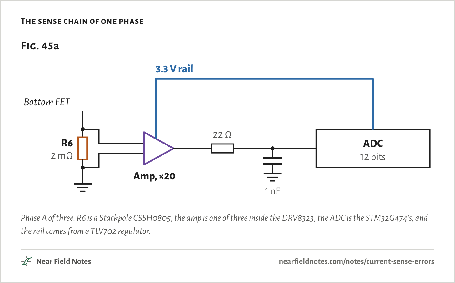
Phase A of three. R6 is a Stackpole CSSH0805, the amp is one of three inside the DRV8323, the ADC is the STM32G474’s, and the rail comes from a TLV702 regulator.
The firmware turns ADC counts into amps with one fixed number, built from the nominal value of every part:
k=Vref4096 · Rs · G
=3.3 V4096 × 2 mΩ × 20=20.1 mA
A real board’s parts are never exactly nominal. Every error below is one part sitting somewhere else inside its datasheet limits. Note 19 covers where a drive’s shunt can sit, and Note 5 covers the error from where the sense traces tap it.
An offset adds the same amps to every reading
4 mV on 2 mΩThe DRV8323’s datasheet lets its amp’s input sit up to 4 mV off. The amp can’t tell that from current in the shunt:
Ios=VosRs
=4 mV2 mΩ=2.0 A
The ADC adds an offset of its own, up to 4 counts. At 20.1 mA a count that is 0.08 A. Its nonlinearity is worth up to 0.07 A more.
Added by root sum square, a stopped motor can read 2.02 A. Nearly all of it is the amp.
A gain error is a share of the reading
Three parts and a railA gain error tilts the whole line. It adds nothing at zero current and the most at full current.
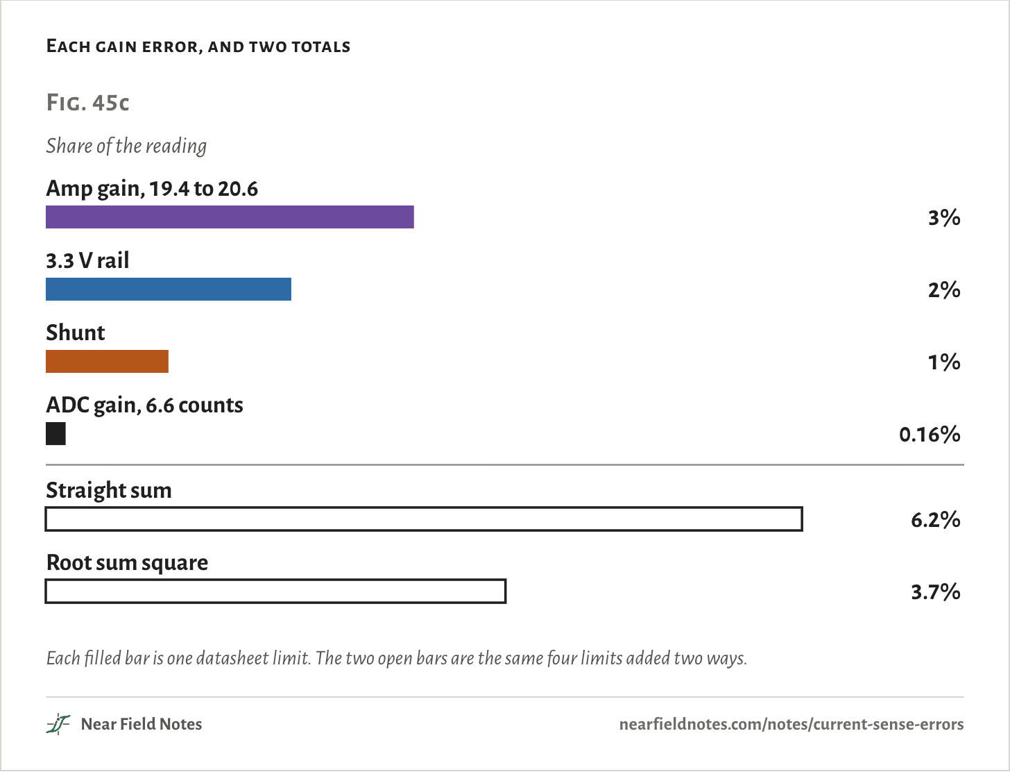
The shunt is a 1% part. The amp’s gain of 20 can be anywhere from 19.4 to 20.6, which is 3%.
The 3.3 V rail is in the measurement too. The ADC counts against it, and the firmware assumes it is exactly 3.3 V. The TLV702 regulator that makes it is a 2% part.
So the 1% shunt is the smallest of the three. The ADC’s own gain error is 0.16%.
Resistance in front of the ADC matters as well. The ADC’s sample capacitor, about 5 pF, charges through whatever sits in front of its pin, and it only has the sample time to do it.
ST publishes the most resistance the source may have. For 12 bits on a fast channel at the shortest sample time, it is 100 Ω. moteus-c1 has 22 Ω in front of each current pin, with 1 nF at the pin. Which channel type and sample time the board uses isn’t confirmed here, so the 100 Ω is ST’s limit and not a verdict on this board.
Worst case, or root sum square
100,000 boardsStack the four gain limits end to end and the total is 6.2%. That is the worst case: every part at its limit, all leaning the same way.
3% + 2% + 1% + 0.16%=6.16%
These four errors are independent, so they rarely all lean the same way. Root sum square adds them at right angles, the way the sides of a triangle add:
3² + 2² + 1² + 0.16²%=3.745%
To see which total holds, I simulated 100,000 boards, each with every part drawn from somewhere inside its limit.
If each datasheet limit is 3 sigma of a bell curve, 99.74% of the boards land inside the root sum square.
If parts are spread evenly across their tolerance, 91.96% do. About 8 boards in 100 land outside, and the worst channel in the run was 6.2% off.
Root sum square is where most boards land, and the straight sum is the edge. A trip limit should use the edge.
Root sum square only works for independent errors. Two errors that share a cause add in a straight line.
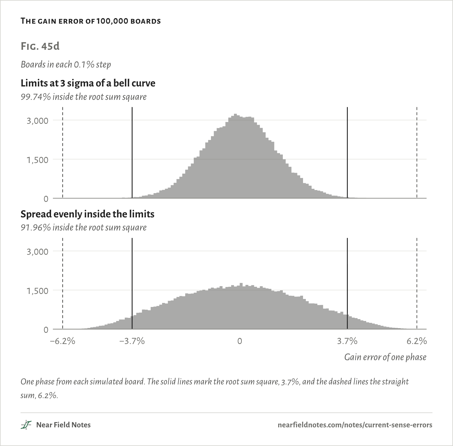
One phase from each simulated board. The solid lines mark the root sum square, 3.7%, and the dashed lines the straight sum, 6.2%.
The numbers
| How parts are spread | Inside the root sum square | Largest of all three phases |
|---|---|---|
| Limits at 3 sigma of a bell curve | 99.74% | 5.9% |
| Spread evenly inside the limits | 91.96% | 6.2% |
Two calibrations
A zero, then a gainAn offset hurts most at low current. With no calibration, a true 1 A can read anywhere from −1 to 3 A.
So zero it. With the motor off, moteus’s firmware averages 256 samples per phase and calls the result zero, every time the driver turns on. A board whose amp sits at its 4 mV limit zeros at 2,147 counts instead of 2,048. Those 99 counts are the whole 2 A.
With the offset gone, the gain error is the big one, and it grows with current. A true 10 A reads 9.5 to 10.5 A.
The second calibration is done once, at the factory. Run a known current through each phase and store the ratio. The first board in my run read 10.09 A at a true 10 A, so it stores 0.991. That one number absorbs the shunt, the amp and the rail, and 10 A now reads 9.7 to 10.3 A.
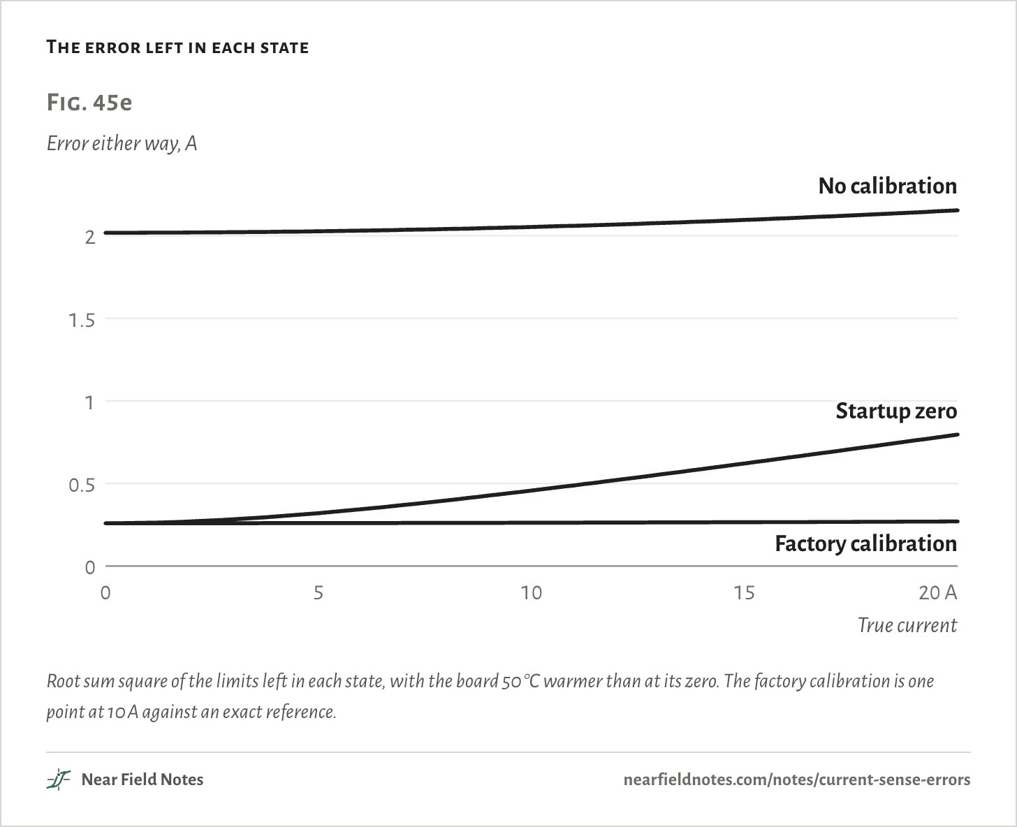
Root sum square of the limits left in each state, with the board 50 °C warmer than at its zero. The factory calibration is one point at 10 A against an exact reference.
The numbers
| State | Added up by | 0 A | 1 A | 5 A | 10 A | 20 A |
|---|---|---|---|---|---|---|
| No calibration | Root sum square | 2.02 A | 2.02 A | 2.03 A | 2.05 A | 2.15 A |
| No calibration | Straight sum | 2.40 A | 2.46 A | 2.73 A | 3.05 A | 3.71 A |
| Startup zero | Root sum square | 0.26 A | 0.26 A | 0.32 A | 0.46 A | 0.80 A |
| Startup zero | Straight sum | 0.32 A | 0.38 A | 0.65 A | 0.97 A | 1.63 A |
| Factory calibration | Root sum square | 0.26 A | 0.26 A | 0.26 A | 0.26 A | 0.27 A |
| Factory calibration | Straight sum | 0.32 A | 0.32 A | 0.34 A | 0.36 A | 0.39 A |
After the zero, what the zero leaves behind and the gain error are equal at 6.9 A. Below that current the leftover offset sets the accuracy. Above it the gain does.
What calibration can’t fix
DriftA zero is only good at the temperature it was taken at. TI gives the DRV8323’s amp a typical offset drift of 10 µV per °C. On a 2 mΩ shunt that is
10 µV per °C2 mΩ=5 mA per °C
If the board warms 50 °C after its zero, the offset can move 0.25 A, and a zero taken at startup can’t see it. That is nearly all of the 0.26 A left at the bottom of Fig. 45e.
A zero-drift amp like the INA240 is held to 0.25 µV per °C, 40 times less. On the same shunt that is 0.125 mA per °C.
What the motor feels
10 A of torque current at 171 rpmA current loop trusts its readings. I simulated a closed loop holding 10 A of torque current, then put each kind of error into what it reads.
An offset on one phase makes the torque ripple once per electrical turn. With 0.25 A of offset, the ripple is 3.2% peak to peak.
A gain mismatch between phases ripples twice per turn. With one phase reading 1% high, it is 0.6% peak to peak, and the torque is 0.33% low.
If all three phases read 3.75% high, there is no ripple. The torque is just 3.6% low.
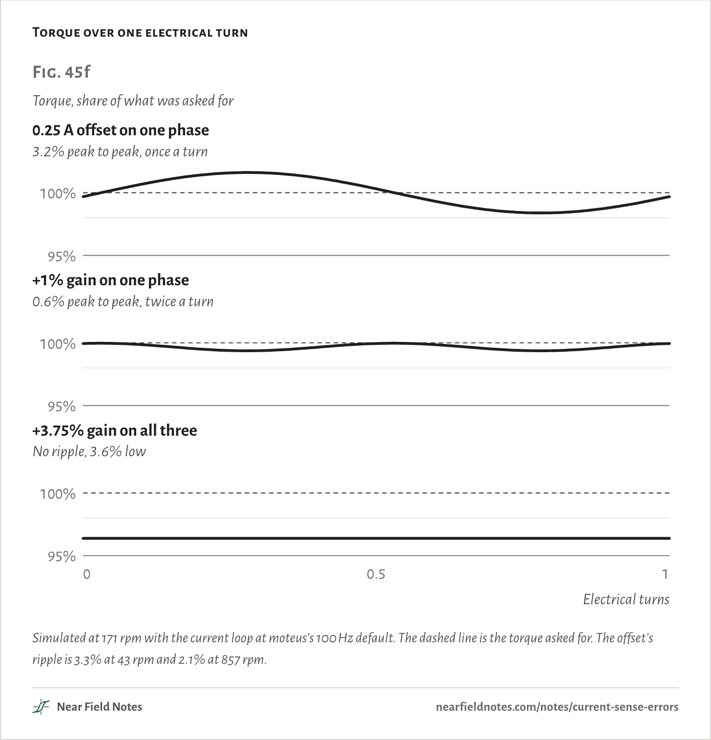
Simulated at 171 rpm with the current loop at moteus’s 100 Hz default. The dashed line is the torque asked for. The offset’s ripple is 3.3% at 43 rpm and 2.1% at 857 rpm.
The numbers
| Error in the readings | Peak to peak | Once a turn | Twice a turn | Mean torque |
|---|---|---|---|---|
| 0.25 A offset on one phase | 3.23% | 1.61% | 0.00% | −0.00% |
| +1% gain on one phase | 0.60% | 0.00% | 0.30% | −0.33% |
| +3.75% gain on all three | 0.00% | 0.00% | 0.00% | −3.61% |
Which error to chase
A keyKey to a current sense error
What is wrong with the reading?
- 1aIt reads current with the motor stoppedOffset. Zero at startup
- 1bIt is right at a standstillGo to 2
- 2aIt moves as the board warmsAmp drift. A zero-drift amp
- 2bIt is off by the same share at any temperatureGain. Calibrate once at a known current
moteus’s firmware does 1a every time the driver turns on.
Conditions
- Board
- One phase of mjbots moteus-c1, read from its KiCad files and firmware: a 2 mΩ shunt (Stackpole CSSH0805FT2L00), the DRV8323S’s built-in amp at a gain of 20, 22 Ω and 1 nF at the pin, the STM32G474’s 12-bit ADC, and one 3.3 V rail from a TLV70233 for the amp’s reference and the ADC’s
- Limits
- Datasheet maximums: shunt ±1% and ±75 ppm per °C, amp gain 19.4 to 20.6, amp input offset ±4 mV, rail ±2%, ADC offset 4 counts, gain 6.6 counts and nonlinearity 3.4 counts. The amp’s offset drift of 10 µV per °C is TI’s typical figure. TI gives no maximum, so it is used here as a limit
- Our picks
- The board is 50 °C warmer at the reading than at its zero. The factory calibration is one point at 10 A against an exact reference
- Adding
- Root sum square of the limits left in each state, unless a figure says straight sum
- Boards
- 100,000 boards of three phases, every part drawn from inside its limit, through the chain and the firmware’s own zero of 256 averaged samples. Run twice: each limit as 3 sigma of a bell curve, and parts spread evenly across their tolerance. ADC noise is 0.76 counts rms, from ST’s 10.6 effective bits
- Motor
- A closed current loop holding 10 A of torque current with moteus’s PI rule at its 100 Hz default. The motor’s 50 mΩ, 30 µH and 7 pole pairs are our picks. Its Kv of 330 is mjbots’ figure for the mj5208
- Video
- The video’s board is built from mjbots’ KiCad board file: the outline, every copper shape on both faces, every pad, the silkscreen text, and each part’s place, turn and side. The package bodies, connectors, colors, silkscreen typeface, solder and phase wires are stand-ins matched by eye to mjbots’ product photos. The motor is a stand-in the size of the mj5208, 63 mm across and 25 mm tall, with 12 coils, a six-spoke bell and no markings. The lit path in the shunt close-up follows phase A’s copper from the motor pad through the low-side FET and R6 to ground, 13.7 mm. The turning motor is slowed: two electrical turns at 171 rpm take 0.1 s, and the video shows them in 4 s. Nothing in it is a photograph or a clip of a real board
These are datasheet limits and model runs. Nothing on this page has been measured on a board.
Limits
- Whether the DRV8323’s ±4 mV is before or after the chip’s own offset trim isn’t confirmed. moteus’s firmware runs that trim at every enable too.
- The amp’s offset drift is a typical figure with no maximum, so the quarter amp over 50 °C isn’t a guaranteed limit either way.
- Whether moteus-c1’s current pins are fast or slow ADC channels, and its ADC clock, aren’t confirmed.
- Factory gain calibration is shown as a general step. moteus’s firmware has no per-board gain value.
- The motor in the torque run is our pick, and its trace is at 171 rpm. The ripple shrinks above the current loop’s bandwidth.
- Using the straight sum for a trip limit is our advice, not a quoted rule.
- The ripple at once and twice per electrical turn is our run. Chung and Sul’s 1998 paper reports the same, and was read as an abstract only.
Files
- sim/boards.py100,000 boards through the chain and the firmware’s zero
- sim/foc.pyThe current loop, with errors put into its readings
Sources
- moteus-c1’s KiCad files, Apache-2.0: current_sense.kicad_sch and power_input.kicad_sch
- moteus’s firmware, Apache-2.0: fw/bldc_servo.cc and fw/drv8323.cc
- TI, DRV8320 and DRV8323 datasheet, SLVSDJ3D, section 7.5
- ST, STM32G474 datasheet: ADC accuracy and Table 67
- Stackpole, CSS and CSSH series datasheet
- TI, TLV702 datasheet
- TI, INA240 datasheet, SBOS662C
- D.-W. Chung and S.-K. Sul, “Analysis and compensation of current measurement error in vector-controlled AC motor drives”, IEEE Transactions on Industry Applications 34(2), 1998
Like this note?
Rev 1 ·
- Rev 1First published
Each fix gets a line here, with the reader's name if they want credit.