---
title: "How can an MOV start a fire?"
topic: "MOV"
answer: "By sitting on a voltage that stays too high. On the 180 V of a broken neutral, a 130 V MOV passes 300 °C in 43 s while drawing 0.14 A, far below what trips a fuse or breaker. A 150 V MOV warms 5 °C on the same 180 V, and it still clamps a 2,000 V surge to 422 V."
url: "https://nearfieldnotes.com/notes/movs/"
site: "Near Field Notes"
author: "Michael Walker"
note: 35
family: "EMC"
published: "2026-11-10"
revised: "2026-11-10"
revision: 1
video: "https://nearfieldnotes.com/videos/movs/"
---
Note 35 · [EMC](https://nearfieldnotes.com/families/emc/) · Rev 1 · [Watch the video · 3:29](https://nearfieldnotes.com/videos/movs/)
MOV
# How can an MOV start a fire?
**Short answer:** By sitting on a voltage that stays too high. On the 180 V of a broken neutral, a 130 V MOV passes 300 °C in 43 s while drawing 0.14 A, far below what trips a fuse or breaker. A 150 V MOV warms 5 °C on the same 180 V, and it still clamps a 2,000 V surge to 422 V.
A surge lasts microseconds, and the MOV is built for it. A stuck overvoltage lasts until someone fixes the wire, and the MOV conducts near every peak of it.
A thermal link that opens near 180 °C takes the 130 V MOV out at 18 s. A PTC in the line does the same job and resets.
**Note 35’s opening figure: One input, three conditions.** What the MOV reaches
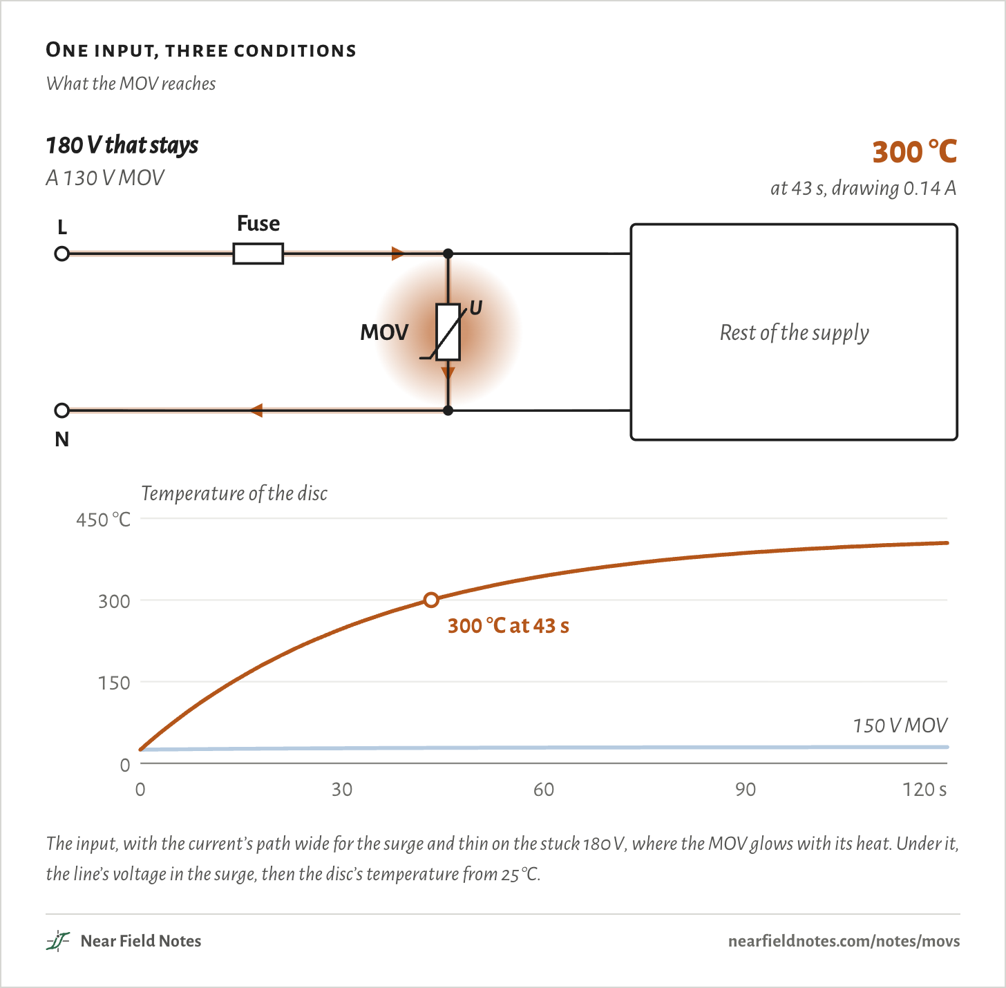
*What the figure shows:* A supply's input in three steps, with a chart under it: the line and neutral come in, a fuse sits in the line, an MOV runs across from line to neutral after it, and the rest of the supply follows. First a 2,000 V test surge: with no MOV the line jumps to 2,000 V, and a 150 V MOV holds it to 422 V while 773 A flows through the fuse and the MOV. Then 180 V that stays, as from a broken neutral: the same 150 V MOV draws 1.7 mA and its temperature stays flat at 30 °C over two minutes. Then a 130 V MOV on the same 180 V: it draws 0.14 A, glows on the drawing, and its temperature climbs through 300 °C at 43 s to 405 °C at two minutes.
The input, with the current’s path wide for the surge and thin on the stuck 180 V, where the MOV glows with its heat. Under it, the line’s voltage in the surge, then the disc’s temperature from 25 °C.
## An MOV on a supply’s input
*120 V line, 20 mm MOV*
An MOV, a metal-oxide varistor, is a disc that sits across the mains to clamp surges. This board is the input of a small supply on a 120 V line.
The line comes in through a fuse. Right after it, the MOV sits across line and neutral, ahead of the X cap, the choke, the bridge and the bulk cap.
When a surge arrives, the MOV conducts, and the current takes the path drawn on the board. [Note 11](https://nearfieldnotes.com/notes/gan-vs-si/) follows what a charger does after its bulk cap.
**Fig. 35a: The board, and a surge’s path.**
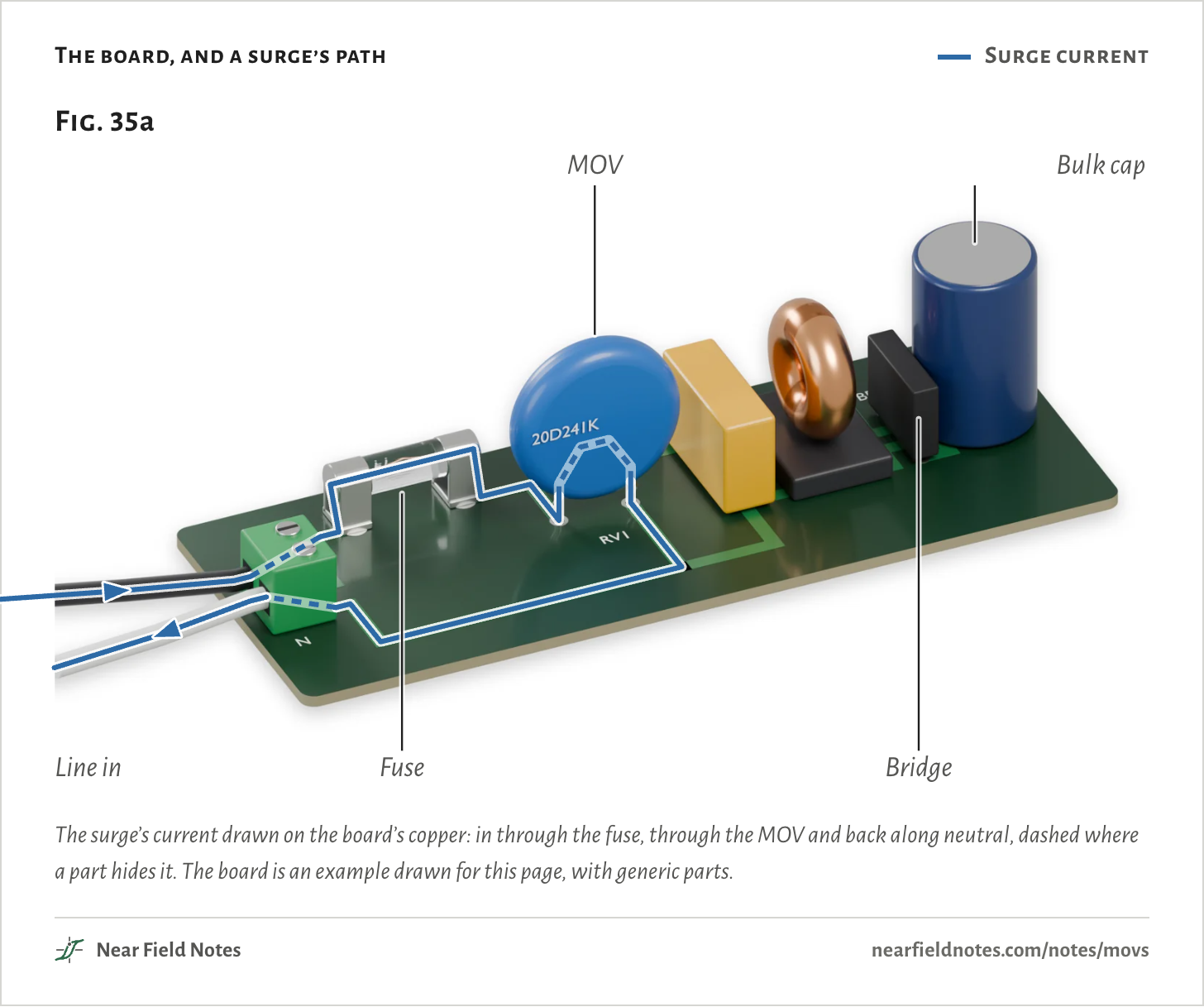
*What the figure shows:* Figure 35a: the input of a small mains supply rendered on a green board. From the left: a black and a white wire in a green screw terminal, a glass fuse in clips, a blue 20 mm disc marked 20D241K standing on two leads, a yellow X2 film capacitor, a copper common-mode choke, a black bridge rectifier and a tall blue bulk capacitor. A line drawn on the copper traces a surge's path: in along the black wire, through the terminal, along the trace and straight through the fuse, to the disc, up one of its leads and down the other, back along the neutral trace and out along the white wire. It is dashed where the terminal or the disc's coating hides it.
The surge’s current drawn on the board’s copper: in through the fuse, through the MOV and back along neutral, dashed where a part hides it. The board is an example drawn for this page, with generic parts.
**The numbers**
| Part | What it is |
|---|---|
| Terminal | Line and neutral in. US colors: black is line, white is neutral |
| Fuse | A 5 × 20 mm glass fuse in clips, in the line |
| MOV | 20 mm, marked 20D241K: 240 V at 1 mA, the 150 V rms class. Right after the fuse, across line and neutral |
| X cap | An X2 film capacitor across the line, for emissions |
| Choke | A common-mode choke in both lines |
| Bridge | A bridge rectifier |
| Bulk cap | 47 µF, 400 V |
| Drawn path | Blue: the surge current, in through the fuse and the MOV and back along neutral. Dashed where a part hides it |
In the circuit, the MOV is a resistor whose value depends on the voltage across it. Its symbol is a resistor crossed by a slanted line and marked U.
At the line’s 170 V peak it is all but open. The 150 V part here draws 50 nA, as much as a 3.4 GΩ resistor would.
**Fig. 35b: The same board, as a circuit.**
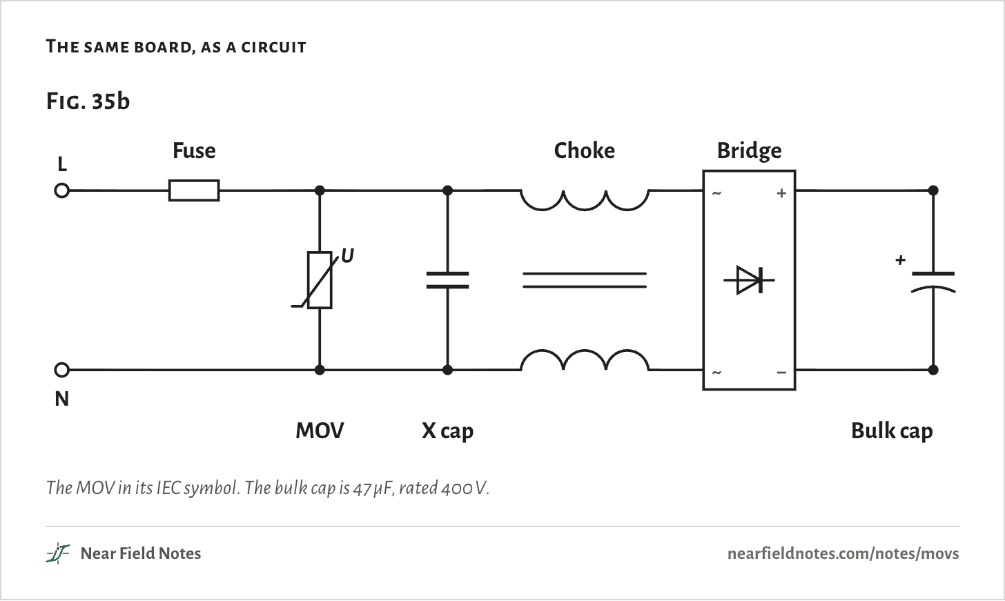
*What the figure shows:* Figure 35b: the board as a circuit. Line and neutral come in at the left. A fuse sits in the line. After it, an MOV, drawn as a resistor with a slanted line through it, runs across from line to neutral, then an X capacitor. A common-mode choke has one winding in each line. A bridge rectifier turns the line into a bus across a 47 microfarad bulk capacitor.
The MOV in its IEC symbol. The bulk cap is 47 µF, rated 400 V.
## Almost no current, then a flood
*Two 20 mm parts*
An MOV’s current climbs steeply with voltage. Across Fig. 35c, the 150 V part’s voltage less than triples while its current grows a trillionfold.
Its name is the rms voltage it can sit on for good. Its datasheet gives two more: 216 to 264 V at 1 mA, and at most 395 V at 100 A.
The 130 V part sits about 15% lower. On a stuck 180 V, whose peaks reach 255 V, that gap is the difference between 5.4 mA and 0.43 A.
**Fig. 35c: Voltage against current.**
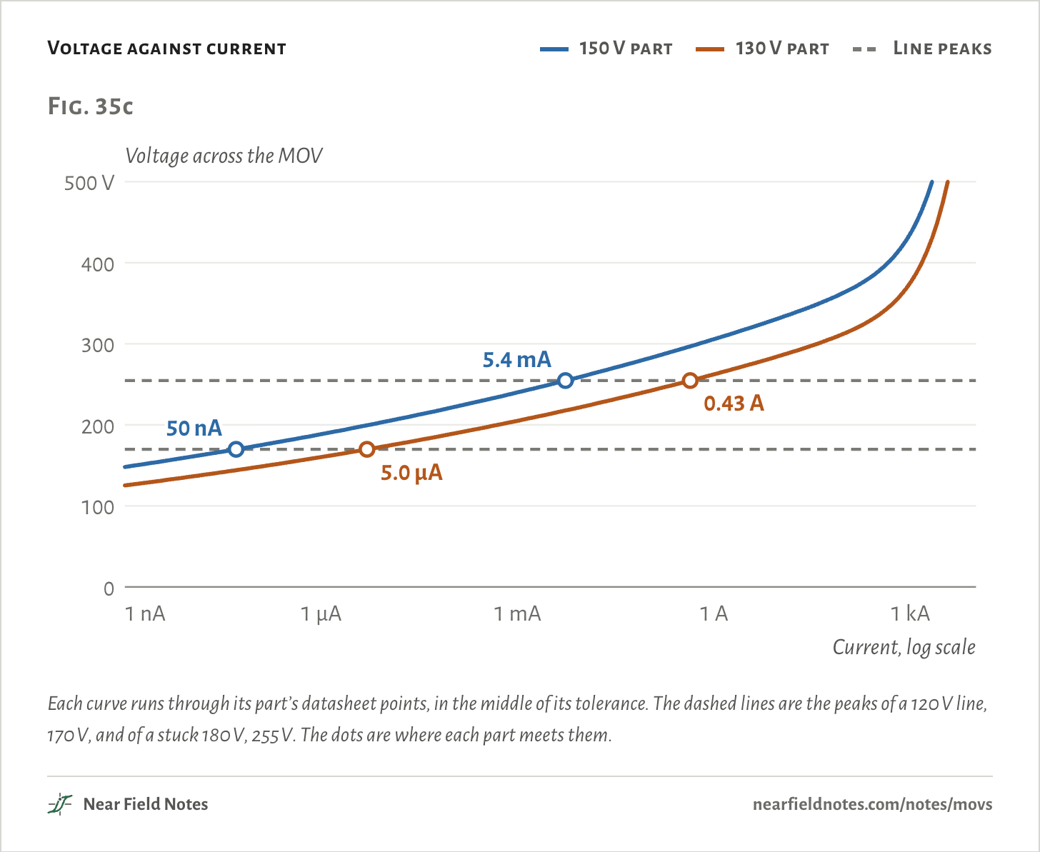
*What the figure shows:* Figure 35c: voltage across the MOV against the current through it, on a log scale from 1 nanoamp to 10 kiloamps, for a 150 V and a 130 V part. Both curves climb only slowly with current: the 150 V part from about 150 V at 1 nanoamp to about 420 V at 1 kiloamp, the 130 V part about 15% lower. At the 120 V line's 170 V peak the 150 V part draws 50 nA and the 130 V part 5.0 µA. At the 255 V peak of a stuck 180 V, the 150 V part draws 5.4 mA and the 130 V part 0.43 A.
Each curve runs through its part’s datasheet points, in the middle of its tolerance. The dashed lines are the peaks of a 120 V line, 170 V, and of a stuck 180 V, 255 V. The dots are where each part meets them.
**The numbers**
*Middle of each part’s tolerance. The datasheet clamp is a maximum.*
| Part | At 1 mA | α | At 170 V | As a resistor | At 255 V | Datasheet, 100 A |
|---|---|---|---|---|---|---|
| *V150LA20A* | 240 V | 28.6 | 50 nA | 3,391 MΩ | 5.4 mA | 395 V |
| *V130LA20A* | 205 V | 28.0 | 5.0 µA | 34 MΩ | 0.43 A | 340 V |
## Inside, a disc of zinc oxide grains
*About 2 to 3.5 V per boundary*
Under the coating is a ceramic disc of zinc oxide, pressed and fired, with an electrode on each face.
The grains conduct well. The thin layers where they meet do not, until each sees about 2 to 3.5 V. A 150 V part, 240 V at 1 mA, has between about 70 and 120 of those boundaries in a row from face to face.
So the disc’s thickness sets its voltage, and its area sets how much current it can take. TDK gives about 30 to 250 V per mm of ceramic.
**Fig. 35d: An MOV, cut open.**
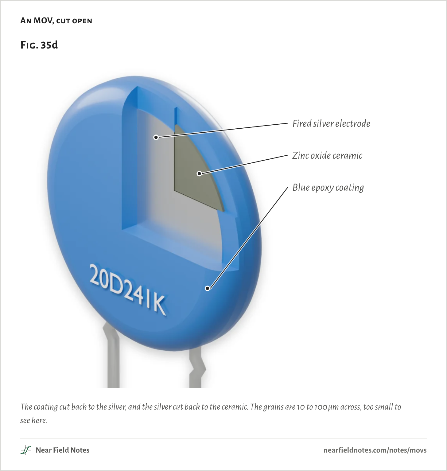
*What the figure shows:* Figure 35d: a 20 mm MOV cut open. A quarter of its blue epoxy coating is cut away, showing a light gray silver layer fired onto the disc, and inside that a smaller quarter of the silver is cut away too, showing the gray zinc oxide ceramic. Two tinned leads come out of the bottom.
The coating cut back to the silver, and the silver cut back to the ceramic. The grains are 10 to 100 µm across, too small to see here.
## A 2,000 V surge, held to 422 V
*IEC 61000-4-5*
The standard test surge comes from IEC 61000-4-5’s combination-wave generator: 2,000 V into an open line, rising in about a microsecond, and about 1,000 A into a short.
Put the 150 V MOV across it and the line peaks at 422 V, while 773 A runs through the MOV.
**Fig. 35e: The 2,000 V surge on the 150 V MOV.**
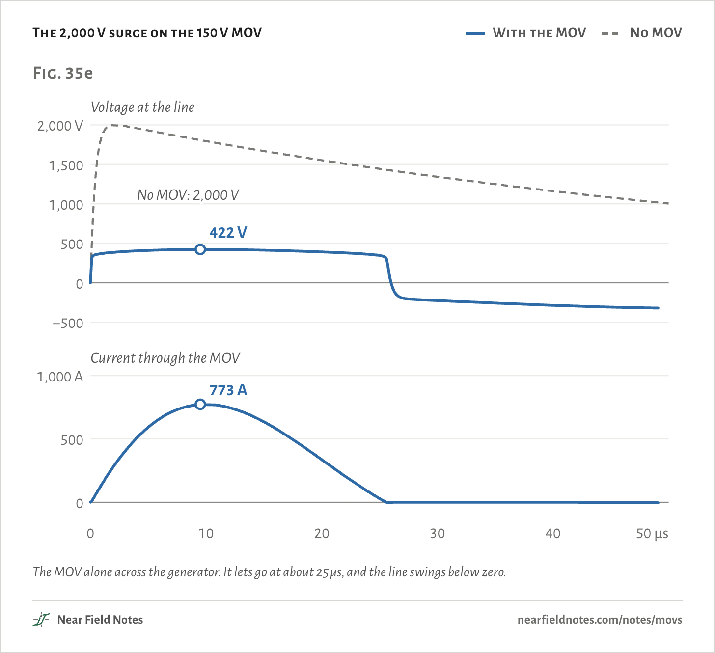
*What the figure shows:* Figure 35e: an IEC 61000-4-5 combination-wave surge set to 2,000 V, against time from 0 to 50 microseconds. With nothing on the line the generator's voltage jumps to 2,000 V in under 2 microseconds and decays slowly. With the 150 V MOV across it, the line rises only to 422 V and holds near 400 V for about 25 microseconds. Then the MOV lets go and the line swings below zero. The MOV's current peaks at 773 A.
The MOV alone across the generator. It lets go at about 25 µs, and the line swings below zero.
**The numbers**
*The MOV alone on the generator. 150 V part unless named. Its rating is 80 J, the 130 V part’s 70 J.*
| Surge | Peak volts | Peak amps | Joules into the MOV |
|---|---|---|---|
| 1 kV | 387 | 294 | 1.7 |
| 2 kV, no MOV | 2,000 | — | — |
| 2 kV | 422 | 773 | 5.8 |
| 4 kV | 479 | 1,740 | 16.9 |
| 2 kV, 130 V MOV | 365 | 803 | 5.5 |
Surge clamp
### 422 V at 773 A
**Field marks.** The 150 V part holds the line near 400 V for about 25 µs, then lets go. It takes 5.8 J of the 80 J it is rated for.
**Look-alike.** A 150 V clamp. The 150 V is the rms voltage it can sit on for good. Its clamp is 2.5 times the line’s 170 V peak.
**Range.** At 1 kV it holds 387 V at 294 A, and at 4 kV 479 V at 1,740 A. The 130 V part holds the 2 kV surge at 365 V, 57 V lower.
**Habitat.** Mains inputs: surge strips, and the air conditioners, refrigerators and TVs TDK lists for its ThermoFuse MOVs.
## Does every supply need one?
*1, 2 and 4 kV*
No. The bulk cap behind the bridge soaks up a surge too. With no MOV, a 1 kV surge lifts it from 170 V to 298 V, well under its 400 V rating.
Power Integrations’ DER-849, a 30 W reference supply, passes ±1 kV line to neutral that way, with 54 µF of bulk cap and no MOV.
At 2 kV the same cap reaches 429 V, past its rating, and at 4 kV 713 V. With the MOV it stays at 303 V and 350 V.
Road and street lights are tested at 2 kV line to neutral under IEC 61547. A survey of 250 US homes, published in 1970, found repeated surges over 1,200 V in 2.4% of them.
**Fig. 35f: The bulk cap after a surge.**
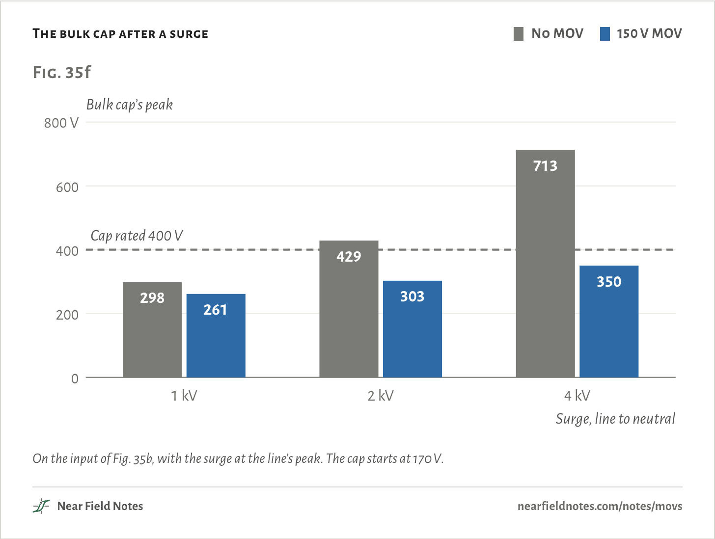
*What the figure shows:* Figure 35f: the bulk capacitor's peak voltage after a surge at 1, 2 and 4 kV, with no MOV and with the 150 V MOV. It starts at 170 V. With no MOV it reaches 298, 429 and 713 V, so past the cap's 400 V rating from 2 kV. With the MOV it reaches 261, 303 and 350 V.
On the input of Fig. 35b, with the surge at the line’s peak. The cap starts at 170 V.
**The numbers**
*Peak values, volts and amps. Surge at the 90° peak of the 120 V line, onto a 47 µF cap charged to 170 V.*
| Surge | Bulk cap, no MOV | With MOV | Bridge amps, no MOV | With MOV | MOV amps |
|---|---|---|---|---|---|
| 1 kV | 298 | 261 | 340 | 241 | 182 |
| 2 kV | 429 | 303 | 680 | 285 | 619 |
| 4 kV | 713 | 350 | 1,360 | 347 | 1,532 |
## Two ways to fail
*Short, or slowly hot*
Each big surge uses up some of the disc. In the pulse rating NIST quotes for 20 mm parts, a disc takes 120,000 surges of 100 A, but only 20,000 of 180 A.
A surge far past its rating cracks the disc or punches through it, and it fails as a short. That failure is the easy one: the fuse ahead of it blows, and the product goes dark.
The other way is slow. A voltage that stays above the MOV’s rating makes it conduct on every cycle, at a current a fuse sized to pass surges will not notice.
**Fig. 35g: A disc after a surge too big for it.**
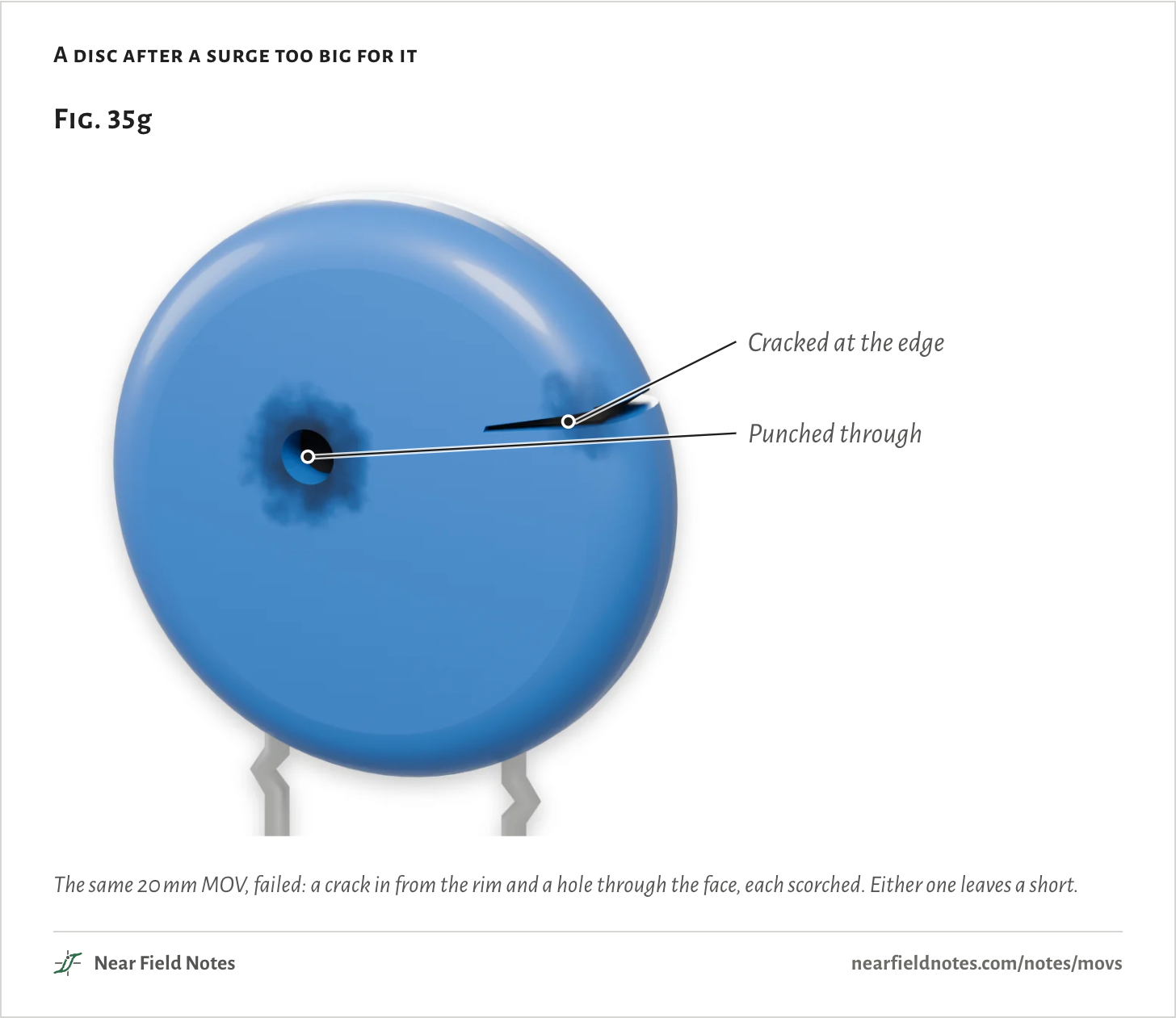
*What the figure shows:* Figure 35g: a 20 mm MOV after surges too big for it. A crack runs in from its rim, scorched at the mouth, and a round hole is punched through its face with soot around it.
The same 20 mm MOV, failed: a crack in from the rim and a hole through the face, each scorched. Either one leaves a short.
## A broken neutral can leave 180 V on an outlet
*NFPA 921’s example*
A US house gets 240 V from a center-tapped transformer: two 120 V legs and a shared neutral.
If the neutral breaks, each leg’s loads end up in series across the 240 V and share it by their size. NFPA 921, the fire investigators’ guide, gives 60 V on one leg and 180 V on the other as an example.
Anything plugged into the lightly loaded leg then sits on 180 V, MOV and all, until the neutral is fixed.
**Fig. 35h: A split-phase supply, neutral broken.**
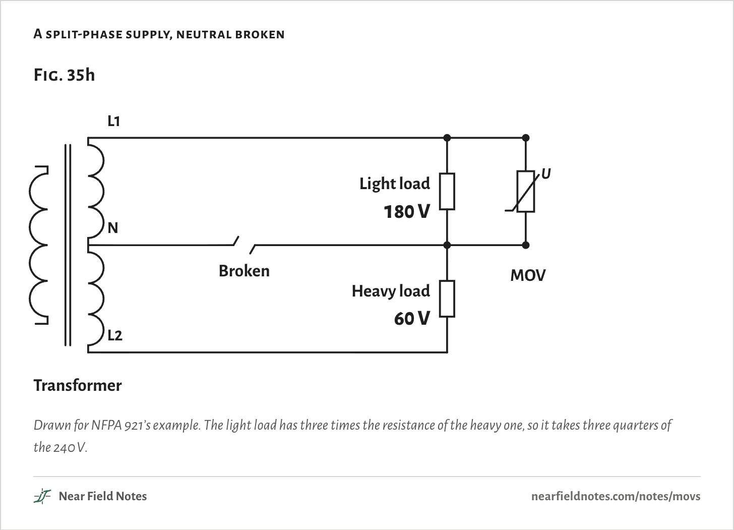
*What the figure shows:* Figure 35h: a house's split-phase supply with its neutral broken. A transformer's center-tapped winding gives two legs, L1 and L2, 120 V each from the neutral in the middle. The neutral wire is drawn broken. A light load and an MOV sit between L1 and the neutral, a heavy load between the neutral and L2. With the neutral gone the two loads share the 240 V in series: 180 V across the light load and its MOV, 60 V across the heavy load.
Drawn for NFPA 921’s example. The light load has three times the resistance of the heavy one, so it takes three quarters of the 240 V.
## On 180 V, the 130 V MOV keeps heating
*300 °C at 43 s*
180 V rms peaks at 255 V. The 130 V part draws 1 mA at 205 V, so near every peak it conducts: pulses of 0.43 A, 0.14 A rms and 16.2 W of heat.
The heat leaves through the two leads, which need 24.4 °C/W of rise to carry each watt away. So the disc climbs toward the air’s temperature plus *P* × *R*_θ, slowed by its own heat capacity:
`T = T_a + P × R_θ × (1 − e^(− t / τ))`
where T: temperature of the disc (°C); T_a: temperature it starts from, the air’s (°C); P: heat the MOV makes, averaged over a cycle (W); R_θ: thermal resistance of its two leads to the board (°C/W); t: time since the voltage arrived (s); τ: thermal time constant, Rθ times the disc’s heat capacity (s).
`= 25 °C + 16.2 W × 24.4 °C/W × (1 − e^(−43 s/36 s)) = 300 °C`
For the 130 V part that level is 419 °C. It passes 300 °C on the way, at 43 s.
**Fig. 35i: Two cycles at 180 V.**
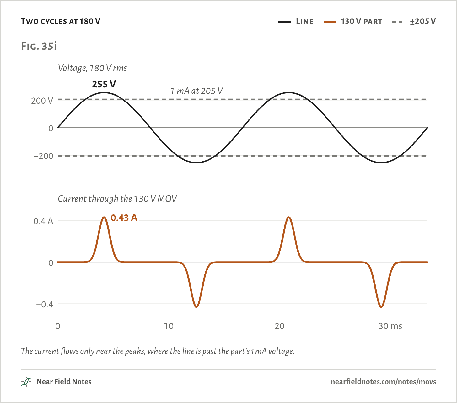
*What the figure shows:* Figure 35i: two cycles of a stuck 180 V rms line, peaking at 255 V, and the current through a 130 V MOV across it. Dashed lines mark 205 V either way, where the part draws 1 mA. Near each peak of the line the current jumps in a narrow pulse to 0.43 A, positive then negative, and between peaks it is close to zero.
The current flows only near the peaks, where the line is past the part’s 1 mA voltage.
**The numbers**
*The middle of each part’s tolerance unless named. The low end is its lowest voltage at 1 mA.*
| At 180 V rms | Peak | Rms | Heat |
|---|---|---|---|
| 130 V part | 0.43 A | 0.14 A | 16.2 W |
| 130 V part, low end | 8.0 A | 2.6 A | 303 W |
| 150 V part | 5.4 mA | 1.7 mA | 0.20 W |
| 150 V part, low end | 0.11 A | 35 mA | 4.0 W |
**Fig. 35j: At 180 V, two MOVs heat up.**
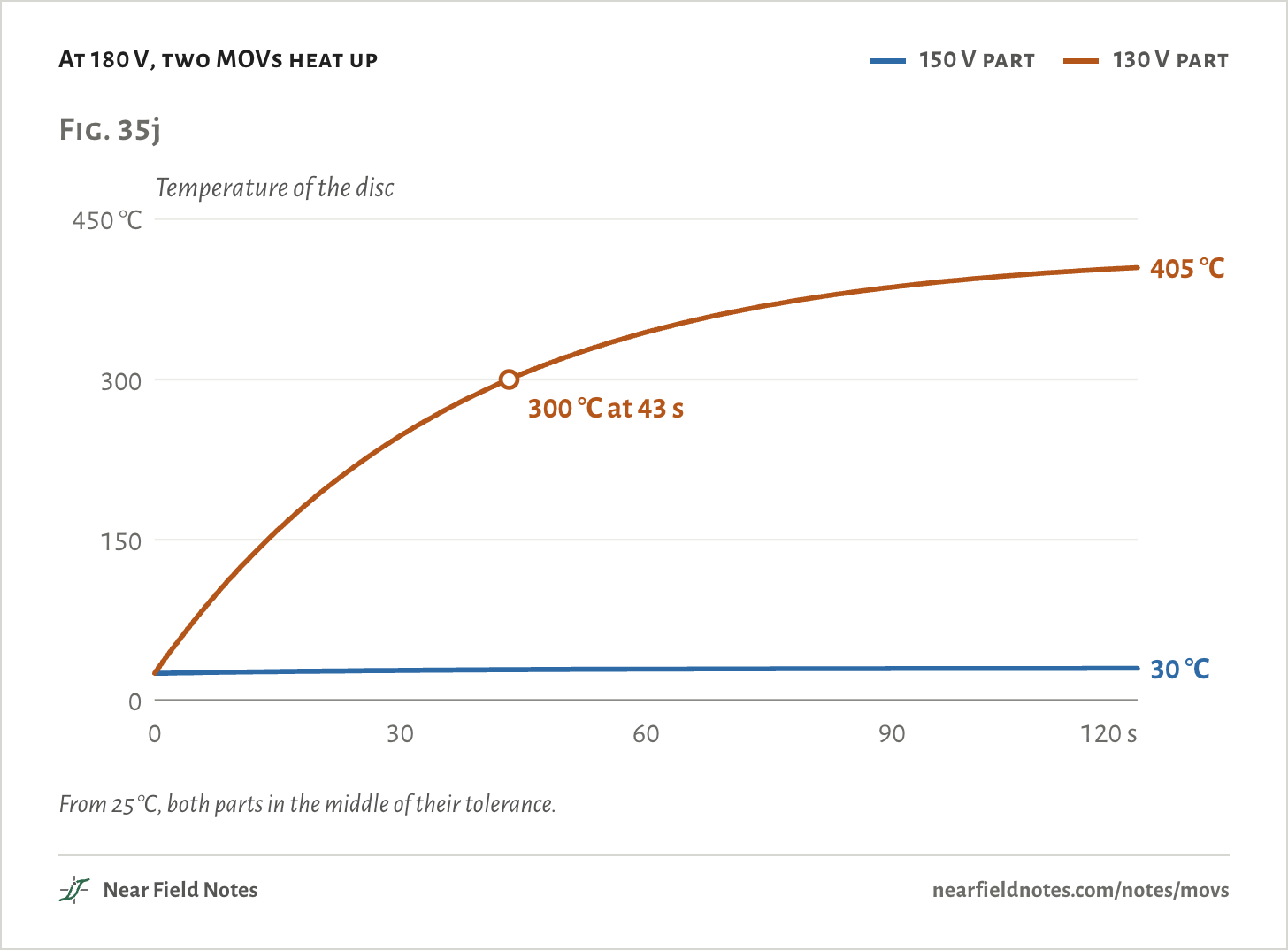
*What the figure shows:* Figure 35j: the temperature of the MOV's disc against time, from 0 to 120 seconds, with 180 V rms held across it from 25 °C. The 150 V part warms by 5 °C and levels off at 30 °C. The 130 V part climbs steeply, passes 300 °C at 43 s and is at 405 °C at 120 seconds, still rising.
From 25 °C, both parts in the middle of their tolerance.
**The numbers**
*From 25 °C. The model has no melting or cracking, so a level-off far above 300 °C only says the disc keeps heating.*
| At 180 V rms | Rms current | Heat | Levels off at | 180 °C at | 300 °C at |
|---|---|---|---|---|---|
| 150 V part | 1.7 mA | 0.20 W | 30 °C | Never | Never |
| 150 V part, low end | 35.4 mA | 4.0 W | 124 °C | Never | Never |
| 130 V part | 0.14 A | 16.2 W | 419 °C | 18 s | 43 s |
| 130 V part, low end | 2.6 A | 303 W | Thousands | 0.8 s | 1.4 s |
130 V MOV on 180 V
### 300 °C at 43 s
**Field marks.** 0.14 A rms, under 1% of a 20 A breaker’s rating, in pulses of 0.43 A. 16.2 W of heat: 180 °C at 18 s, 300 °C at 43 s.
**Look-alike.** A lower clamp protects better. The 130 V part does clamp the 2 kV surge 57 V lower. NIST titled its 1989 paper on the choice “Lower is not better”.
**Range.** On the same 180 V the 150 V part draws 1.7 mA and warms 5 °C. At the low end of its tolerance it levels off at 124 °C.
**Habitat.** In a 2024 NAFE case, a tree broke a house’s neutral and a power tap’s MOV started a fire. The 20 A breaker tested as working.
## A thermal link pulls the MOV off the line
*Opens near 180 °C*
A thermally protected MOV has a thermal fuse in series with the disc, pressed against it. In Littelfuse’s patent for its TMOV, the fuse is a solder wire that melts at about 180 °C, balls up and pulls away, and a hot-melt fills the gap.
It works once. The MOV is gone, and the product keeps running with no surge protection. Littelfuse’s iTMOV adds a third lead to report it.
**Fig. 35k: A thermally protected MOV.**
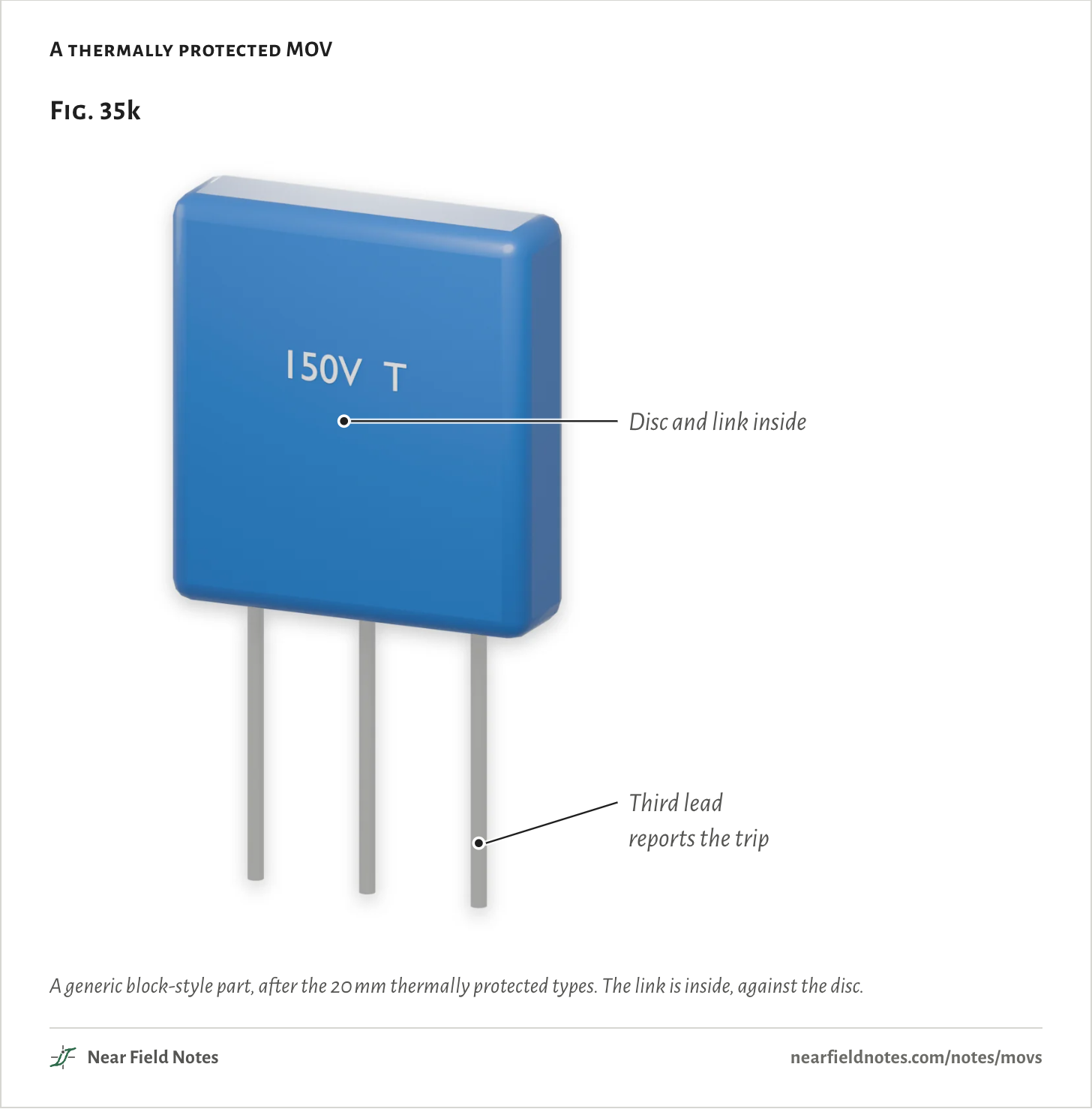
*What the figure shows:* Figure 35k: a thermally protected MOV, a flat blue block marked 150 V T with three tinned leads. The disc and its thermal link are inside the block. The third lead reports when the link has opened.
A generic block-style part, after the 20 mm thermally protected types. The link is inside, against the disc.
Modeled as a link that opens at 180 °C, it takes the 130 V part off the 180 V at 18 s. The disc then cools through its leads.
Without the link, the same part would pass 300 °C at 43 s.
**Fig. 35l: The link opens.**
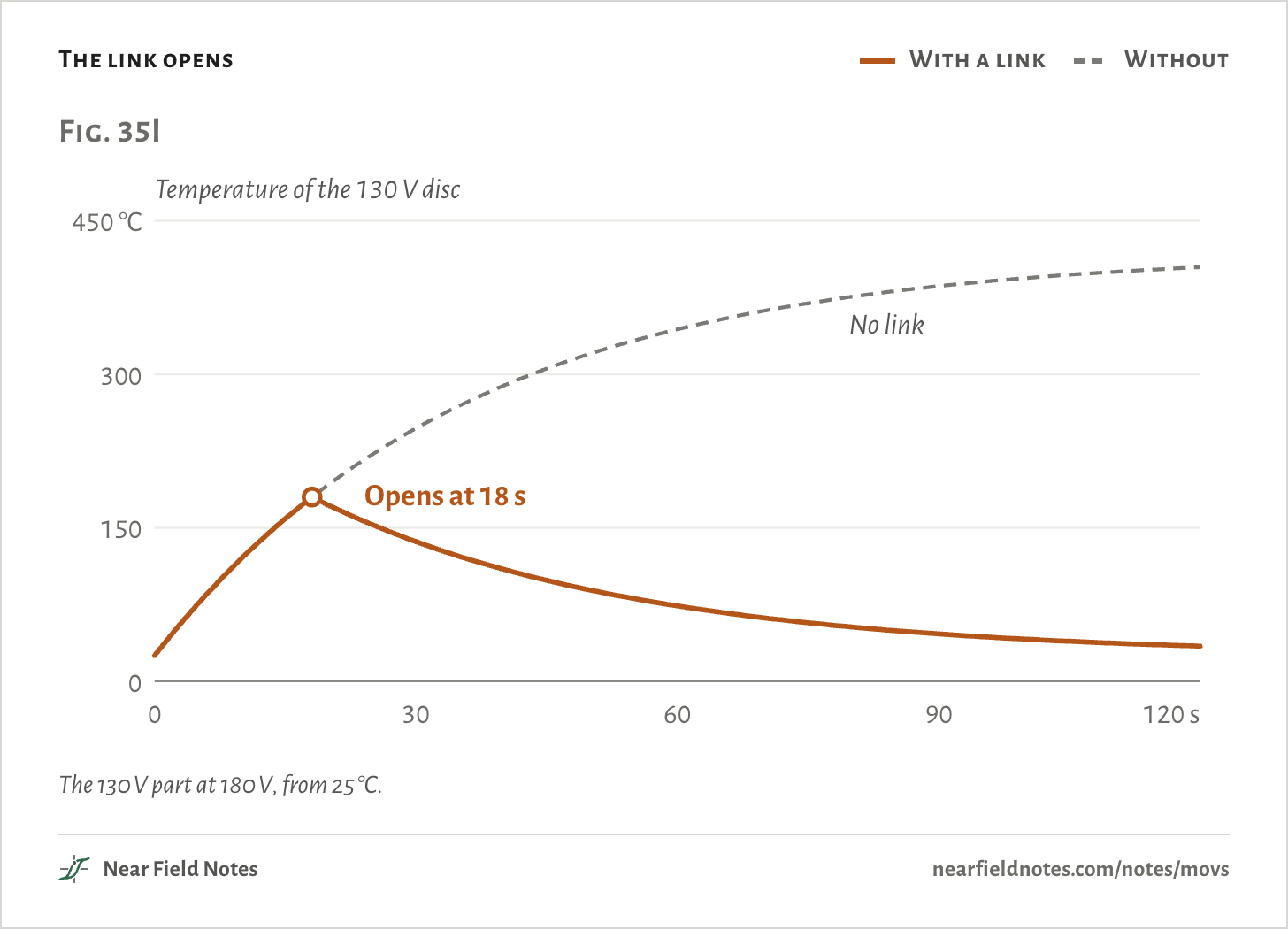
*What the figure shows:* Figure 35l: the 130 V MOV's temperature at 180 V rms with a thermal link that opens at 180 °C. It climbs as before, the link opens at 18 s, and the disc cools back toward 25 °C, at 34 °C by 120 seconds. Without the link, drawn dashed, it would pass 300 °C at 43 s.
The 130 V part at 180 V, from 25 °C.
**The numbers**
*130 V part at 180 V rms, from 25 °C. The link opens at 180 °C, at 18.1 s.*
| Time | With the link | Without |
|---|---|---|
| 0 s | 25 °C | 25 °C |
| 10 s | 120 °C | 120 °C |
| 18 s | 180 °C | 180 °C |
| 30 s | 136 °C | 247 °C |
| 60 s | 74 °C | 344 °C |
| 90 s | 46 °C | 386 °C |
| 120 s | 34 °C | 405 °C |
## Or a PTC that cuts the power and resets
*Up to 75 VA on 120 V*
A PTC is a resistor that jumps to a high value when it gets hot. The 2Pro, made by TE and now sold by Littelfuse, puts one in the line and an MOV right after it, in one body. The MOV’s heat trips the PTC, and the load loses power.
TE tests it at 400 V, a lost neutral on a 230 V line, and it holds the MOV under 150 °C. TE warns that a plain 275 V MOV there may overheat even with a fuse upstream.
It resets once it cools. All the load’s current runs through the PTC, so it suits small loads, up to 75 VA on 120 V.
**Fig. 35m: An MOV with a PTC in the line.**
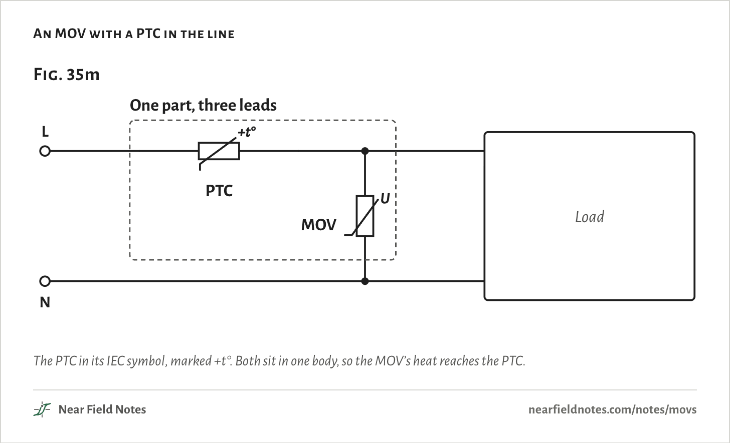
*What the figure shows:* Figure 35m: an MOV with a PTC in one part. The line runs through a PTC thermistor, drawn as a resistor crossed by a slant and marked plus t degrees, and on to the load. The MOV runs from the PTC's far side to neutral. A dashed box around both shows they share one body, so the MOV's heat reaches the PTC.
The PTC in its IEC symbol, marked +t°. Both sit in one body, so the MOV’s heat reaches the PTC.
## What the standards ask
*Three of them*
No product safety standard makes a product fit an MOV. Once one is fitted, the standards test how it fails.
**Figure: What each standard asks of an MOV.**
Fig. 35n
| Standard | Covers | What it does to an MOV | A pass |
|---|---|---|---|
| UL 1449 | Surge protectors, a power strip’s included | Holds it at full line-to-line voltage, the current limited in steps down to 0.125 A for a plug-in strip, for up to 7 h | No flame, molten metal or holes in the case. Disconnecting counts |
| IEC 62368-1, Annex G.8 | Audio, video and IT equipment | Treats it as a possible ignition source, rated at least 1.25 times the line. Rated 1.25 to 2 times: twice the line voltage through a resistor, from 0.125 A and doubled each run. Over 2 times, line to neutral: no test | A fuse or thermal fuse that opens before fire |
| IEC 60335-1 | Household appliances | Shorts it as a fault, even one with a thermal link, per VDE’s 2021 ruling. Its 2 kV surge test runs with the MOV taken out | Something ahead of it, like a fuse, clears the short safely |
Paraphrased from documents about the standards, all in the sources below, not from the standards’ own text: DeGregoria’s slides and Mersen’s note on UL 1449, Maytum’s slides on IEC 62368-1, and VDE’s ruling and an SGS test report on IEC 60335-1. A thermal link or a fuse that opens before anything burns is a pass in the first two.
## Hold a voltage yourself
*130 and 150 V parts, 120 to 240 V*
Pick a part, where it sits in its tolerance, and a voltage held across it from 25 °C. The curve is the disc’s temperature.
In the middle of its tolerance the 150 V part stays under 180 °C up to 202 V, and the 130 V part up to 174 V. At the low end those fall to 183 V and 157 V.
**Note 35’s explorer: The disc’s temperature, against time.**
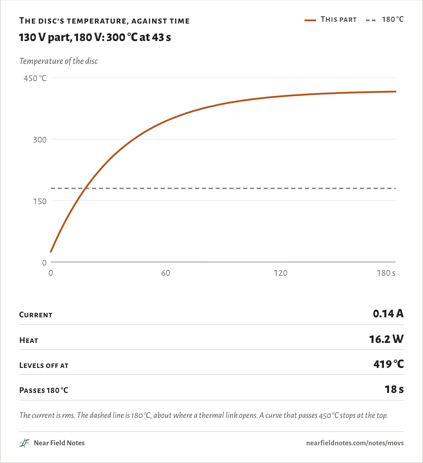
*What the figure shows:* The temperature of the MOV's disc against time, from 0 to 180 seconds, with the chosen voltage held across the chosen part from 25 °C. A dashed line marks 180 °C, about where a thermal link opens. A curve that passes 450 °C stops at the top.
The current is rms. The dashed line is 180 °C, about where a thermal link opens. A curve that passes 450 °C stops at the top.
**The numbers**
*Five of the 25 voltages for each part and tolerance. From 25 °C.*
| Part | Held | Rms current | Heat | Levels off at | 180 °C at |
|---|---|---|---|---|---|
| 130 V, middle | 150 V | 849.6 µA | 0.08 W | 27 °C | Never |
| 130 V, middle | 165 V | 12 mA | 1.3 W | 57 °C | Never |
| 130 V, middle | 180 V | 0.14 A | 16.2 W | 419 °C | 18 s |
| 130 V, middle | 200 V | 2.6 A | 337 W | Over 450 °C | 0.7 s |
| 130 V, middle | 240 V | 145 A | 24,580 W | Over 450 °C | Under 0.1 s |
| 130 V, low end | 150 V | 16 mA | 1.6 W | 63 °C | Never |
| 130 V, low end | 165 V | 0.24 A | 24.8 W | Over 450 °C | 11 s |
| 130 V, low end | 180 V | 2.6 A | 302 W | Over 450 °C | 0.8 s |
| 130 V, low end | 200 V | 36.4 A | 4,824 W | Over 450 °C | 0.1 s |
| 130 V, low end | 240 V | 414 A | 76,980 W | Over 450 °C | Under 0.1 s |
| 150 V, middle | 150 V | 9.5 µA | Under 0.01 W | 25 °C | Never |
| 150 V, middle | 165 V | 145.2 µA | 0.02 W | 25 °C | Never |
| 150 V, middle | 180 V | 1.7 mA | 0.20 W | 30 °C | Never |
| 150 V, middle | 200 V | 35 mA | 4.5 W | 134 °C | Never |
| 150 V, middle | 240 V | 6.1 A | 935 W | Over 450 °C | 0.2 s |
| 150 V, low end | 150 V | 193.4 µA | 0.02 W | 25 °C | Never |
| 150 V, low end | 165 V | 2.9 mA | 0.31 W | 33 °C | Never |
| 150 V, low end | 180 V | 35 mA | 4.0 W | 124 °C | Never |
| 150 V, low end | 200 V | 0.71 A | 90.5 W | Over 450 °C | 2.6 s |
| 150 V, low end | 240 V | 68.4 A | 11,120 W | Over 450 °C | Under 0.1 s |
## Fit one, and guard it how?
*Three questions*
Which way fits depends on three things: what a surge does to the supply without an MOV, how high the MOV is rated, and how much the load draws.
Key to an MOV on a mains input
### Does it need one, and what stops it burning?
1. 1a At the product’s test surge, the bulk cap stays under its rating No MOV
2. 1b It goes over Go to 2
3. 2a The MOV is rated over twice the line voltage A plain MOV
4. 2b It is rated 1.25 to 2 times the line voltage Go to 3
5. 3a The load is small, up to 75 VA on 120 V An MOV with a PTC
6. 3b The load is bigger A thermally protected MOV
IEC 62368-1 wants an MOV rated at least 1.25 times the line voltage, so on 120 V the 130 V part is out before the key starts. Over twice the line voltage, it lets a line-to-neutral MOV skip its overload test. The board in Fig. 35a has a 150 V MOV, exactly 1.25 times its line, and its 47 µF cap goes past 400 V at 2 kV, so it reaches 3.
#### Conditions
- **Simulated:** Every voltage, current and temperature on this page comes from a simulation. None was measured.
- **MOV:** NIST’s model: a power law, *I* = *k**V*^α, in series with a bulk resistance, fitted to Littelfuse’s datasheet points at 1 mA and 100 A. *V150LA20A*: 216 to 264 V at 1 mA, 395 V at 100 A, α 28.6, 0.047 Ω, 1.6 nF. *V130LA20A*: 184.5 to 225.5 V, 340 V, α 28.0, 0.040 Ω, 1.9 nF. The middle of tolerance is the middle of the 1 mA range, and the low end its bottom.
- **Surge:** ngspice. IEC 61000-4-5’s combination wave from Carobbi and Bonci’s generator circuit with its 18 µF coupling capacitor: 1.2/50 µs into an open line, 8/20 µs into a short. The MOV alone across it, and the input of Fig. 35b: 1.5 mH to the mains, a 0.1 µF X cap, the MOV, 0.5 Ω and 5 µH for the fuse, choke and traces, a bridge and a 47 µF bulk cap at 170 V, with the surge at the line’s peak.
- **Heating:** NIST’s model: a 3 g disc of zinc oxide, 1.48 J/°C, losing heat only through two copper leads 0.81 mm across and 10 mm long, 24.4 °C/W, with no air cooling. Its time constant is 36 s. The heat is the average over one 60 Hz cycle of 20,000 points. *k* and α stay fixed as the disc heats, as in NIST’s paper.
- **Check:** For a low-end 130 V part, NIST’s paper gives about +130 °C at 156 V and nearly +300 °C at 160 V. This rebuild gives +119 °C and +247 °C.
- **Thermal link:** Opens at 180 °C, the link wire’s melting point in Littelfuse’s patent. The disc then cools through the same leads.
- **Runs:** 11 surge runs in ngspice. 113 heating cases, 100 of them for the explorer.
- **Video:** The video says about 80 grain boundaries. This page gives the range, 70 to 120, from 2 to 3.5 V per boundary.
- **Renders:** Blender, the video’s models rendered again on white. Generic parts.
Simulated only. Nothing on this page has been measured on a board yet.
#### Limits
- The model’s curve stays put as the disc heats. NIST gives a real part’s 1 mA voltage as falling 0.05% per °C, with the effect fading above 1 mA, so a hot disc conducts somewhat more than modeled.
- Heat leaves only by the leads, NIST’s worst case. Air and the board would carry some of it away.
- Nothing melts, cracks or burns in the model. Far past 300 °C it only says the disc keeps heating.
- The clamp has no upturn past the bulk resistance, so at kiloamps it reads a little low.
- Wear from earlier surges is not modeled. A worn MOV leaks more and runs away at a lower voltage.
- 120 V only. On 230 V the same story runs with a 275 V part and about 400 V from a broken neutral, TE’s test voltage.
#### Files
- sim/mov.py The MOV model and the two parts’ datasheet numbers
- sim/surge.py The surge generator, the input circuit and its surge runs
- sim/runaway.py The heating model, its check against NIST and the thermal link
- sim/site.py The runs added for this page: the V-I curves, the explorer’s states, the limits and the 130 V part’s surge
- render/parts.py The board and the MOVs in Blender
#### Sources
- [Martzloff and Leedy, NIST, 1989: Selecting varistor clamping voltage: lower is not better. The model, the check and the pulse ratings](https://www.nist.gov/document/lowernotbetterpdf)
- [Littelfuse LA series datasheet, *V130LA20A* and *V150LA20A*](https://xdevs.com/doc/Keithley/2182A/doc/Littelfuse_Varistor_LA_Datasheet.pdf.pdf)
- [TDK SIOV metal oxide varistors, general technical information: grains, boundaries and volts per mm](https://en.tdk-electronics.tdk.com/download/531268/8954d4a78154a9da5c70a7119fa03e86/siov-general.pdf)
- [Al Martin, In Compliance, 2020: how and why varistors fail](https://incompliancemag.com/how-and-why-varistor-failure-occurs-including-the-effect-of-multipulse-surges/)
- [Littelfuse AN9772, varistor design examples: how MOVs fail](https://docs.rs-online.com/b9ec/0900766b800a9c32.pdf)
- [IEC 61000-4-5, the surge test, with Hesterman’s and Carobbi and Bonci’s generator values](https://en.wikipedia.org/wiki/IEC_61000-4-5)
- [Power Integrations DER-849, a 30 W supply with no MOV](https://www.power.com/sites/default/files/documents/der-849_30watt_isolated_flyback_power_supply_for_smart_speakers_using_innoswitch3-cp.pdf)
- [Mean Well’s summary of IEC 61547, lighting surge levels](https://expo.meanwell.com/upload/data/SafetyNews/EN/EMC-IEC61547.pdf)
- [Martzloff and Hahn, 1970: surges in 250 homes](https://www.nist.gov/document/res-ind-surgespdf)
- [Interian and Pietropaolo, Journal of the NAFE, 2024: the lost-neutral fire, quoting NFPA 921’s 60 V and 180 V](https://journal.nafe.org/ojs/index.php/nafe/article/view/917)
- [US 6,636,403 B2, Littelfuse’s thermally protected MOV](https://patents.google.com/patent/US6636403B2/en)
- [Littelfuse TMOV and iTMOV datasheet, 2008](https://pccomponents.com/datasheets/LITTELFUSE-TMOV_ITMOV.PDF)
- [EPCOS ETFV14 ThermoFuse varistor datasheet, its applications](https://docs.rs-online.com/163c/0900766b8115910b.pdf)
- [TE 2Pro AC brochure, 2012: its PTC, its 400 V test and its 75 VA rating on 120 V](https://hkjdwchip.com/image//files/teconnectivity-lvm2p015r10431-datasheets-9456.pdf)
- [Littelfuse *LVM2P-015R10431* specification](https://store.comet.bg/download-file.php?id=17210)
- [DeGregoria, UL, 2018: slides giving an overview of UL 1449, with surge strips tested down to 0.125 A](https://peg.atis.org/wp-content/uploads/2018/08/Overview_of_UL1449-JDegregoria.pdf)
- [Mersen CPN3: UL 1449’s limited-current tests, and wear lowering an MOV’s voltage](https://www.mersen.com/sites/default/files/files_imported_ep/TT-CPN3-Addressing-Overcurrent-Issues-for-Surge-Protective-Devices-Tech-Topic.pdf)
- [Maytum, 2019: slides on IEC 62368-1 Annex G.8 and its overload test](https://peg.atis.org/wp-content/uploads/2019/03/IEC62368-1_and_Pluggable_Mains_Powered_Equipment_Surge_Protection-MMaytum.pdf)
- [VDE EK1 decision 731-21: shorting varistors under EN 60335-1](https://www.vde.com/resource/blob/2089932/70fc7f39ad6bc1948f670cd245b66f16/731-21-data.pdf)
- [An SGS test report to IEC 60335-1: surge protective devices taken out for the clause 19.11.4.4 surge test](https://www.heatpressleader.com/uploads/file/lvd-test-report.pdf)
- [ngspice, the circuit simulator](https://ngspice.sourceforge.io/)
What should the next note be? [Ask for one](https://nearfieldnotes.com/#ask-for-a-note)
---
Source: https://nearfieldnotes.com/notes/movs/
Cite as: Michael Walker, “MOV”, Near Field Notes, Note 35, Rev 1, 10 Nov 2026. https://nearfieldnotes.com/notes/movs/
Figures: free to reuse under CC BY 4.0 (https://nearfieldnotes.com/license/). Each one's image is linked under its name. Credit Michael Walker, Near Field Notes, and link the figure: this address plus #fig- and its number, like https://nearfieldnotes.com/notes/movs/#fig-35a.